1997 MERCEDES-BENZ ML500 roof
[x] Cancel search: roofPage 3040 of 4133
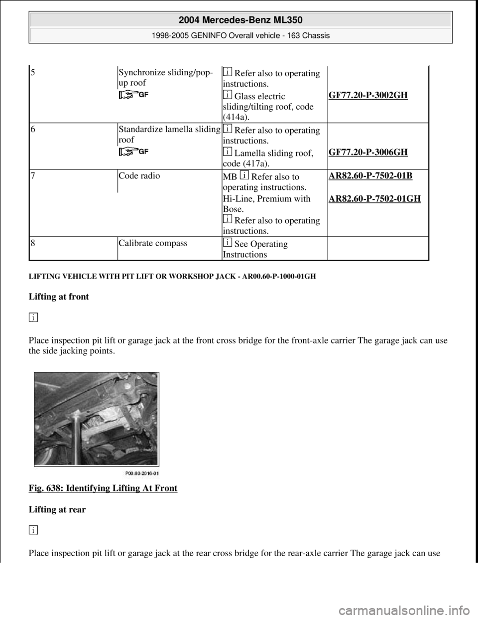
LIFTING VEHICLE WITH PIT LIFT OR WORKSHOP JACK - AR00.60-P-1000-01GH
Lifting at front
Place inspection pit lift or garage jack at the front cross bridge for the front-axle carrier The garage jack can use
the side jacking points.
Fig. 638: Identifying Lifting At Front
Lifting at rear
Place inspection pit lift or
garage jack at the rear cross bridge for the rear-axle carrier The garage jack can use
5Synchronize sliding/pop-
up roof Refer also to operating
instructions.
Glass electric
sliding/tilting roof, code
(414a).GF77.20-P-3002GH
6Standardize lamella sliding
roof Refer also to operating
instructions.
Lamella sliding roof,
code (417a).GF77.20-P-3006GH
7Code radioMB Refer also to
operating instructions.AR82.60-P-7502-01B
Hi-Line, Premium with
Bose.
Refer also to operating
instructions.AR82.60-P-7502-01GH
8Calibrate compass See Operating
Instructions
2004 Mercedes-Benz ML350
1998-2005 GENINFO Overall vehicle - 163 Chassis
me
Saturday, October 02, 2010 3:47:52 PMPage 395 © 2006 Mitchell Repair Information Company, LLC.
Page 3146 of 4133
1. Hypoid gear oils
Hypoid gear oils contain a high level of EP/AW additives (Extreme Pressure/Antiwear) and a highly
viscous base oil to prevent seizure when the hypoid gears mesh (mixed and boundary friction conditions)
and to ensure a high degree of protection against wear. The compatibility with radial shaft seals is
regarded as critical with such high concentrations of additives because the P/S additive systems become
thermally unstable at temperatures from 130°C to 140°C and this may lead to sludging of the hypoid oil.
The resultant deposits on the radial shaft seals then generally lead to thermal overload and this in turn
leads to leakage in this component.
The tooth engagement conditions of the hypoid gears result in a high proportion of sliding and a low
hydrodynamic proportion of tooth engagement between the pinion and ring gear. Due to the high
tribological load compared to adhesive wear (seizure) and pitting, the performance of hypoid gear oils
must be particularly high with respect to these types of wear. The formula of the oils is therefore
determined by a high concentration of EP/AW additives and a highly viscous base oil. Alternative oils,
e.g. engine oils, cannot be used for these drive types. Proof of performance that an oil fulfills the
requirements of DaimlerChrysler AG is provided by internal tests. However, the hypoid gear oils must at
least correspond to the US military specification MIL-L-2105 B/C/D and must be classed GL-5 in the
quality grade according to API (American Institute of Petroleum).
1.7 Viscosity requirements
The cold flow behavior is only specified for SAE, ... oils. Here, the limits apply according to SAE J 306
c, according to which the dynamic viscosity may be max. 150,000 mPas at -40°C for oils and at -12°C for
oils. As a result of the tendency to form deposits in the transmission, the polymer content is limited to
max.
1 percent by weight for pour point reducers. Polymers as VI improvers for thickening low-viscosity base
oils are not permitted. The kinematic viscosity at 100°C must be at least 16.5 mm
2 /s.
2. Transmission oils, sheet 235.1
The additive and viscosity properties of the transmission oils are adjusted so that they meet all the
requirements placed on manual transmissions with steel/molybdenum synchronization, spur gear axles,
MB and ZF transfer cases and reversing gears. Among other things, this results in the fact that the oils
ensure a defined friction coefficient of the synchronizer elements, even after a high number of shift
operations, without crunching noises.
With gear drives and roller bearings, the adhesive wear (seizure) and pitting in particular should be
minimized as far as possible.
2.1 Viscosity requirements
The cold flow behavior is only specified for SAE, 80W, ...oils. Here, the limits according to SAE J 306 c
apply, according to which the dynamic viscosity may be max. 150,000 mPas at -40°C for oils, at -26°C
for oils and at -12°C for oils. Due to the formation of deposits in the transmission, the polymer content is
limited to max. 1 percent b
y weight for pour point reducers. Polymers as VI improvers for thickening
2004 Mercedes-Benz ML350
1998-2005 GENINFO Overall vehicle - 163 Chassis
me
Saturday, October 02, 2010 3:47:56 PMPage 501 © 2006 Mitchell Repair Information Company, LLC.
Page 3193 of 4133
AR88.40-P-3020GH
Adjust engine hood
8.4.99
MODEL
163.113 /128 /136 /154 /157 /172 /174 /175
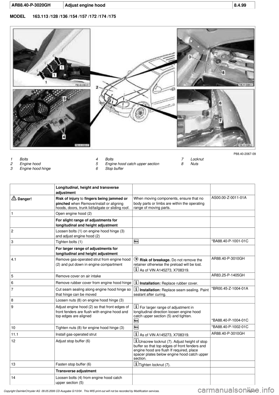
P88.40-2067-09
1
Bolts
2
Engine hood
3
Engine hood hinge
7
Locknut
8
Nuts
4
Bolts
5
Engine hood catch upper section
6
Stop buffer
Longitudinal, height and transverse
adjustment
Danger!
Risk of injury
to
fingers being jammed or
pinched
when Remove/install or aligning
hoods, doors, trunk lid/tailgate or sliding roof.
When moving components, ensure that no
body parts or limbs are within the operating
range of moving parts.
AS00.00-Z-0011-01A
1
Open engine hood (2)
For slight range of adjustments for
longitudinal and height adjustment
2
Loosen bolts (1) on engine hood hinge (3)
and adjust engine hood (2)
3
Tighten bolts (1)
*BA88.40-P-1001-01C
For larger range of adjustments for
longitudinal and height adjustment
4.1
Remove gas-operated strut from engine hood
(2) and put down in engine compartment
Risk of breakage. Do not remove the
retainer otherwise the preload will be lost.
AR88.40-P-3010GH
As of VIN A145273, X708319.
5
Remove cover on air intake
AR83.25-P-1405GH
6
Remove rubber cover from engine hood hinge
Installation:
Replace rubber cover.
7
Cut seam sealing along engine hood hinge so
that hinge can be moved
Installation:
Replace seam sealing. Paint
sealant after curing.
*BR00.45-Z-1004-01A
8
Loosen nuts (8) on engine hood hinge (3)
9
Adjust engine hood (2) so that front edges of
front fenders are flush with engine hood and
top edges are aligned
For larger range of adjustment in
longitudinal direction loosen engine hood
catch upper section (5) and tighten.
*BA88.40-P-1004-01C
10
Tighten nuts (8) for engine hood hinge (3)
*BA88.40-P-1002-01C
11.1
Install gas-operated strut
As of VIN A145273, X708319.
AR88.40-P-3010GH
12
Adjust stop buffer (6)
Unscrew locknut (7). Adjust height of stop
buffer so that top edges of front fenders and
engine hood are flush If required, place
spacer plates below engine hood catch upper
section.
13
Fasten stop buffer (6)
Tighten locknut (7).
Transverse adjustment
14
Loosen bolts (4) from engine hood catch
upper section (5)
Copyright DaimlerChrysler AG 09.05.2006 CD-Ausgabe G/10/04 . This WIS print-out will not be recorde
d by Modification services.
Page 1
Page 3195 of 4133
AR88.40-P-3020GH
Adjust engine hood
8.4.99
MODEL
163.113 /128 /136 /154 /157 /172 /174 /175
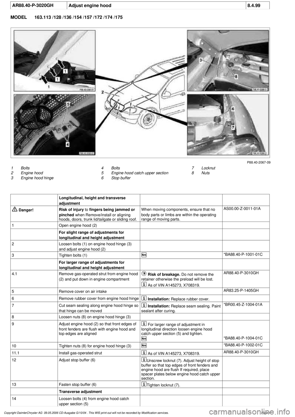
P88.40-2067-09
1
Bolts
2
Engine hood
3
Engine hood hinge
7
Locknut
8
Nuts
4
Bolts
5
Engine hood catch upper section
6
Stop buffer
Longitudinal, height and transverse
adjustment
Danger!
Risk of injury
to
fingers being jammed or
pinched
when Remove/install or aligning
hoods, doors, trunk lid/tailgate or sliding roof.
When moving components, ensure that no
body parts or limbs are within the operating
range of moving parts.
AS00.00-Z-0011-01A
1
Open engine hood (2)
For slight range of adjustments for
longitudinal and height adjustment
2
Loosen bolts (1) on engine hood hinge (3)
and adjust engine hood (2)
3
Tighten bolts (1)
*BA88.40-P-1001-01C
For larger range of adjustments for
longitudinal and height adjustment
4.1
Remove gas-operated strut from engine hood
(2) and put down in engine compartment
Risk of breakage. Do not remove the
retainer otherwise the preload will be lost.
AR88.40-P-3010GH
As of VIN A145273, X708319.
5
Remove cover on air intake
AR83.25-P-1405GH
6
Remove rubber cover from engine hood hinge
Installation:
Replace rubber cover.
7
Cut seam sealing along engine hood hinge so
that hinge can be moved
Installation:
Replace seam sealing. Paint
sealant after curing.
*BR00.45-Z-1004-01A
8
Loosen nuts (8) on engine hood hinge (3)
9
Adjust engine hood (2) so that front edges of
front fenders are flush with engine hood and
top edges are aligned
For larger range of adjustment in
longitudinal direction loosen engine hood
catch upper section (5) and tighten.
*BA88.40-P-1004-01C
10
Tighten nuts (8) for engine hood hinge (3)
*BA88.40-P-1002-01C
11.1
Install gas-operated strut
As of VIN A145273, X708319.
AR88.40-P-3010GH
12
Adjust stop buffer (6)
Unscrew locknut (7). Adjust height of stop
buffer so that top edges of front fenders and
engine hood are flush If required, place
spacer plates below engine hood catch upper
section.
13
Fasten stop buffer (6)
Tighten locknut (7).
Transverse adjustment
14
Loosen bolts (4) from engine hood catch
upper section (5)
Copyright DaimlerChrysler AG 09.05.2006 CD-Ausgabe G/10/04 . This WIS print-out will not be recorde
d by Modification services.
Page 1
Page 3199 of 4133
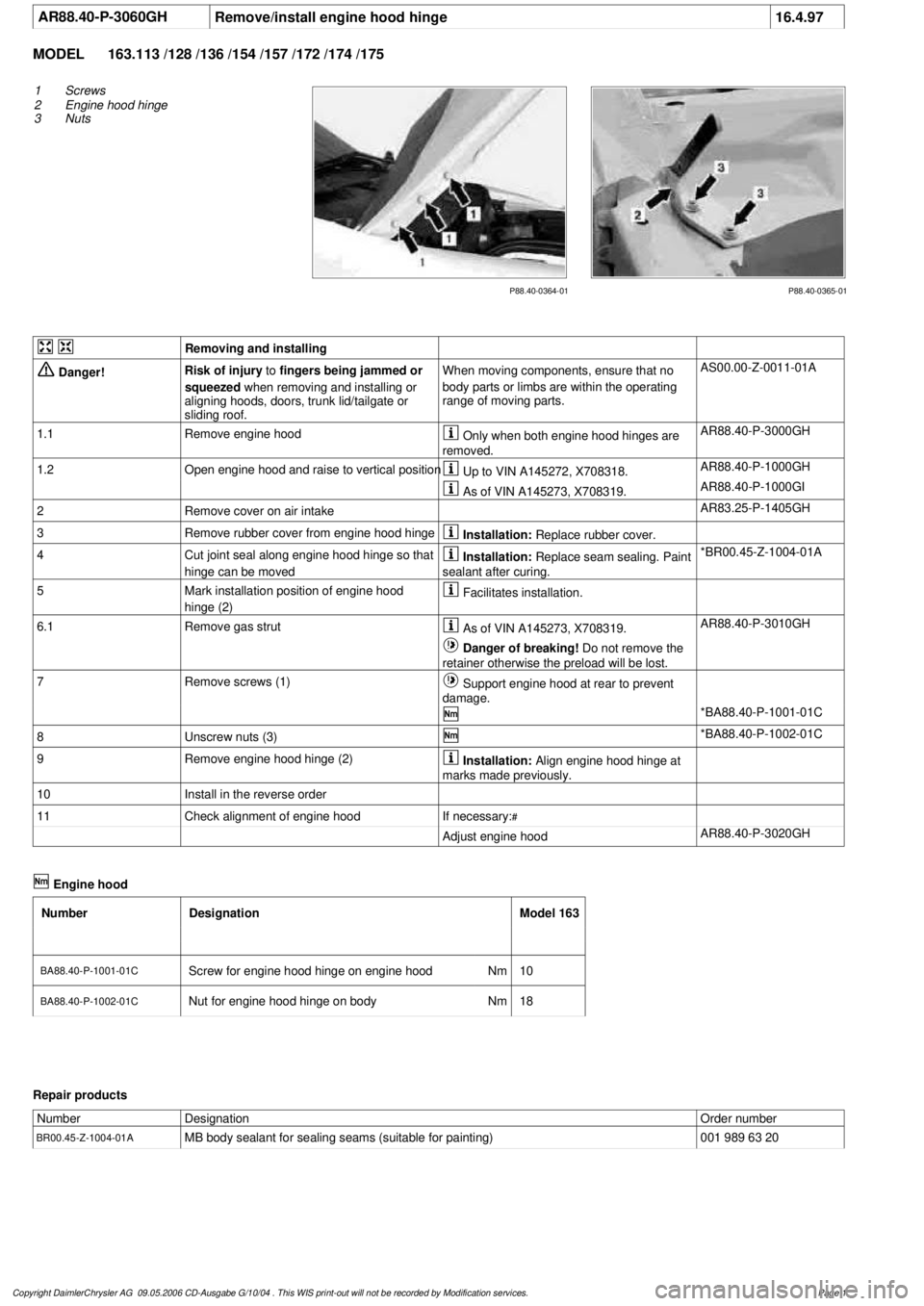
AR88.40-P-3060GH
Remove/install engine hood hinge
16.4.97
MODEL
163.113 /128 /136 /154 /157 /172 /174 /175
P88.40-0365-01
P88.40-0364-01
1
Screws
2
Engine hood hinge
3
Nuts
Removing and installing
Danger!
Risk of injury
to
fingers being jammed or
squeezed
when removing and installing or
aligning hoods, doors, trunk lid/tailgate or
sliding roof.
When moving components, ensure that no
body parts or limbs are within the operating
range of moving parts.
AS00.00-Z-0011-01A
1.1
Remove engine hood
Only when both engine hood hinges are
removed.
AR88.40-P-3000GH
1.2
Open engine hood and raise to vertical position
Up to VIN A145272, X708318.
AR88.40-P-1000GH
As of VIN A145273, X708319.
AR88.40-P-1000GI
2
Remove cover on air intake
AR83.25-P-1405GH
3
Remove rubber cover from engine hood hinge
Installation:
Replace rubber cover.
4
Cut joint seal along engine hood hinge so that
hinge can be moved
Installation:
Replace seam sealing. Paint
sealant after curing.
*BR00.45-Z-1004-01A
5
Mark installation position of engine hood
hinge (2)
Facilitates installation.
6.1
Remove gas strut
As of VIN A145273, X708319.
AR88.40-P-3010GH
Danger of breaking!
Do not remove the
retainer otherwise the preload will be lost.
7
Remove screws (1)
Support engine hood at rear to prevent
damage.
*BA88.40-P-1001-01C
8
Unscrew nuts (3)
*BA88.40-P-1002-01C
9
Remove engine hood hinge (2)
Installation:
Align engine hood hinge at
marks made previously.
10
Install in the reverse order
11
Check alignment of engine hood
If necessary:
#
Adjust engine hood
AR88.40-P-3020GH
Engine hood
Number
Designation
Model 163
BA88.40-P-1001-01C
Screw for engine hood hinge on engine hood
Nm
10
BA88.40-P-1002-01C
Nut for engine hood hinge on body
Nm
18
Repair products
Number
Designation
Order number
BR00.45-Z-1004-01A
MB body sealant for sealing seams (suitable for painting)
001 989 63 20
Copyright DaimlerChrysler AG 09.05.2006 CD-Ausgabe G/10/04 . This WIS print-out will not be recorde
d by Modification services.
Page 1
Page 3209 of 4133
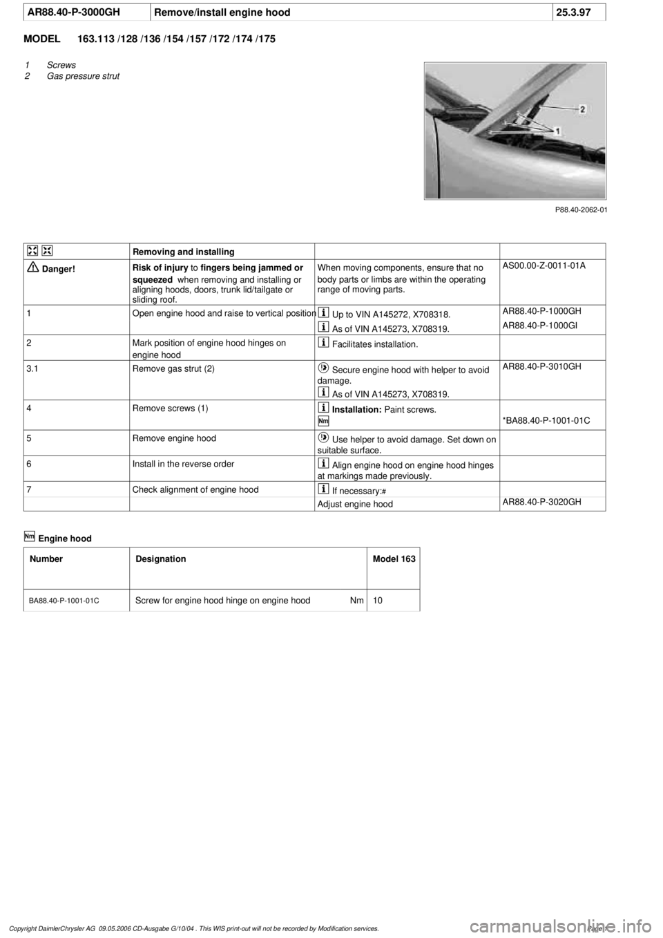
AR88.40-P-3000GH
Remove/install engine hood
25.3.97
MODEL
163.113 /128 /136 /154 /157 /172 /174 /175
P88.40-2062-01
1
Screws
2
Gas pressure strut
Removing and installing
Danger!
Risk of injury
to
fingers being jammed or
squeezed
when removing and installing or
aligning hoods, doors, trunk lid/tailgate or
sliding roof.
When moving components, ensure that no
body parts or limbs are within the operating
range of moving parts.
AS00.00-Z-0011-01A
1
Open engine hood and raise to vertical position
Up to VIN A145272, X708318.
AR88.40-P-1000GH
As of VIN A145273, X708319.
AR88.40-P-1000GI
2
Mark position of engine hood hinges on
engine hood
Facilitates installation.
3.1
Remove gas strut (2)
Secure engine hood with helper to avoid
damage.
AR88.40-P-3010GH
As of VIN A145273, X708319.
4
Remove screws (1)
Installation:
Paint screws.
*BA88.40-P-1001-01C
5
Remove engine hood
Use helper to avoid damage. Set down on
suitable surface.
6
Install in the reverse order
Align engine hood on engine hood hinges
at markings made previously.
7
Check alignment of engine hood
If necessary:
#
Adjust engine hood
AR88.40-P-3020GH
Engine hood
Number
Designation
Model 163
BA88.40-P-1001-01C
Screw for engine hood hinge on engine hood
Nm
10
Copyright DaimlerChrysler AG 09.05.2006 CD-Ausgabe G/10/04 . This WIS print-out will not be recorde
d by Modification services.
Page 1
Page 3248 of 4133
All models fitted with air conditioning
Do not carry repair operations out on the air conditioning circuit in the open air during moist weather.
Moisture in the refrigerant circuit reduces the system's refrigeration output and leads to damage to the
components. The acidic substances produced by moisture within the system decompose the desiccant in the
fluid reservoir and damage the entire system.
After separating/unscrewing refrigerant lines, immediately seal off the connection openings so that they are
airproof using suitable stop plugs (parts kit).
Replace the fluid reservoir every time you open up the refrigeration circuit.
Always store all spare components in a dry, sealed-off area. Do not remove stop plugs in new components until
just before they are installed. Use special care when handling the receiver/dryer with its integral desiccation
unit.
When a receiver/dryer is left open, the dryer unit quickly becomes saturated with moisture, rendering it useless.
Check drier cartridge packaging for damage. Dispose of drier cartridges with damaged packaging.
Install the desiccant cartridge no later than 20 minutes after opening the packaging.
Further protection against moisture is provided by carefully evacuating the air conditioning system following
repair operations. By generating vacuum in the system, the evacuation process removes any moisture that might
have penetrated into the system.
NOTES ON RETROFITTING AN AIR CONDITIONING SYSTEM - AH83.30-P-0001-02A
Do not remove the plugs on any of the components until immediately prior to installation.
Fit all AC lines with new sealing rings. Coat thread and sealing rings with compressor oil.
BASIC KNOWLEDGE
VENTILATION, FUNCTION - GF83.10-P-2000GH
MODEL 163 up to 31.8.01
2001 Mercedes-Benz ML320
1998-2005 HVAC Climate Control - 163 Chassis
me
Saturday, October 02, 2010 3:23:14 PMPage 4 © 2006 Mitchell Repair Information Company, LLC.
Page 3258 of 4133
The blower regulator then controls the blower motor operating voltage, depending on the actual measured in-car
temperature and the selected target temperature
(0-12 V). This facilitates blower speed control of 0-100 %.
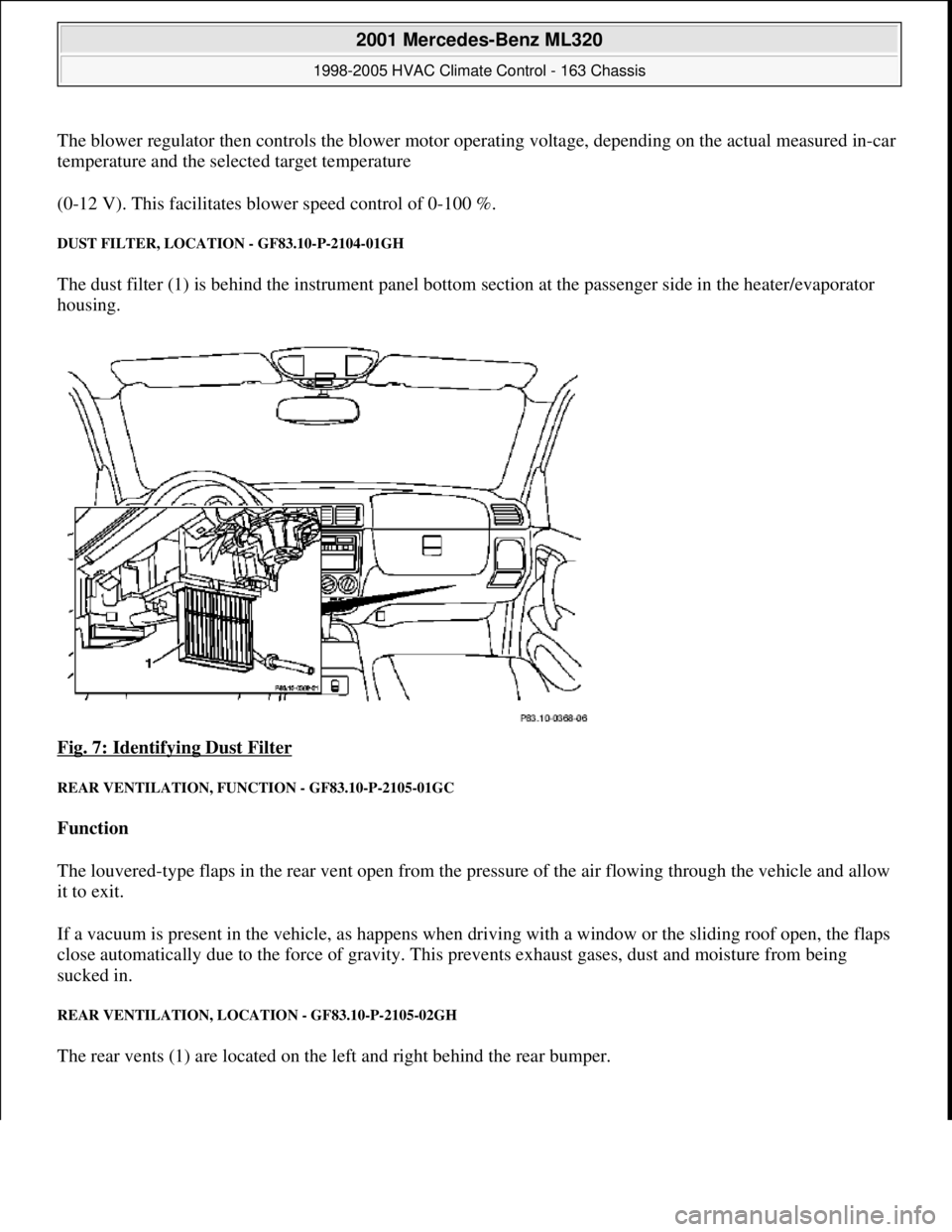
DUST FILTER, LOCATION - GF83.10-P-2104-01GH
The dust filter (1) is behind the instrument panel bottom section at the passenger side in the heater/evaporator
housing.
Fig. 7: Identifying Dust Filter
REAR VENTILATION, FUNCTION - GF83.10-P-2105-01GC
Function
The louvered-type flaps in the rear vent open from the pressure of the air flowing through the vehicle and allow
it to exit.
If a vacuum is present in the vehicle, as happens when driving with a window or the sliding roof open, the flaps
close automatically due to the force of gravity. This prevents exhaust gases, dust and moisture from being
sucked in.
REAR VENTILATION, LOCATION - GF83.10-P-2105-02GH
The rear vents (1) are located on the left and right behind the rear bumper.
2001 Mercedes-Benz ML320
1998-2005 HVAC Climate Control - 163 Chassis
me
Saturday, October 02, 2010 3:23:14 PMPage 14 © 2006 Mitchell Repair Information Company, LLC.