Page 1868 of 4133
Fig. 286: Identifying Mark On Center Monitor Bracket
16. Adhere bracket to crossmember ribs.
Align the center incision (14) of the monitor bracket to the marking on the crossmember (25). Guide
lugs (15) of the bracket latch at front in the grooves (26) of the crossmember.
17. Route monitor wiring harness (8) through opening (16) in rear area of bracket.
18. Provide bore hole with Ø = 5 mm through bracket and crossmember.
Use guide hole (17) provided in the bracket. To prevent damage to the vehicle roof, limit drilling depth
to 5 mm. Cover interior to collect the chips.
19. Rivet bracket with rivet supplied to crossmember of tiltin
g/sliding roof frame.
2001 Mercedes-Benz ML320
1998-2005 ACCESSORIES & BODY, CAB Electrical System - Body - 163 Chassis
me
Saturday, October 02, 2010 3:30:12 PMPage 373 © 2006 Mitchell Repair Information Company, LLC.
Page 1869 of 4133
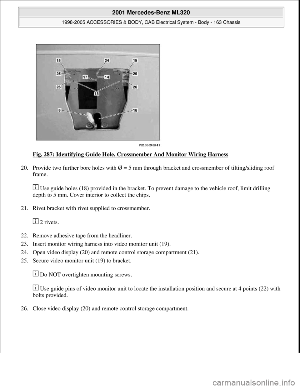
Fig. 287: Identifying Guide Hole, Crossmember And Monitor Wiring Harness
20. Provide two further bore holes with Ø = 5 mm through bracket and crossmember of tilting/sliding roof
frame.
Use guide holes (18) provided in the bracket. To prevent damage to the vehicle roof, limit drilling
depth to 5 mm. Cover interior to collect the chips.
21. Rivet bracket with rivet supplied to crossmember.
2 rivets.
22. Remove adhesive tape from the headliner.
23. Insert monitor wiring harness into video monitor unit (19).
24. Open video display (20) and remote control storage compartment (21).
25. Secure video monitor unit (19) to bracket.
Do NOT overtighten mounting screws.
Use guide pins of video monitor unit to locate the installation position and secure at 4 points (22) with
bolts provided.
26. Close video displa
y (20) and remote control storage compartment.
2001 Mercedes-Benz ML320
1998-2005 ACCESSORIES & BODY, CAB Electrical System - Body - 163 Chassis
me
Saturday, October 02, 2010 3:30:12 PMPage 374 © 2006 Mitchell Repair Information Company, LLC.
Page 1886 of 4133
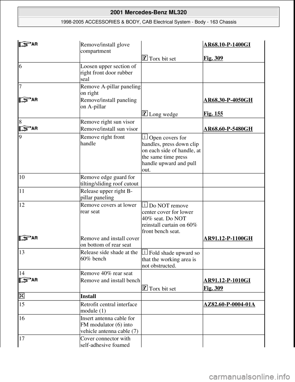
Remove/install glove
compartment AR68.10-P-1400GI
Torx bit setFig. 309
6Loosen upper section of
right front door rubber
seal
7Remove A-pillar paneling
on right
Remove/install paneling
on A-pillar AR68.30-P-4050GH
Long wedgeFig. 155
8Remove right sun visor
Remove/install sun visor AR68.60-P-5480GH
9Remove right front
handle Open covers for
handles, press down clip
on each side of handle, at
the same time press
handle upward and pull
out.
10Remove edge guard for
tilting/sliding roof cutout
11Release upper right B-
pillar paneling
12Remove covers at lower
rear seat Do NOT remove
center cover for lower
40% seat. Do NOT
reinstall curtain on 60%
front bench seat.
Remove and install cover
on bottom of rear seat AR91.12-P-1100GH
13Release side shade at the
60% bench Fold shade upward so
that the working area is
not obstructed.
14Remove 40% rear seat
Remove and install bench AR91.12-P-1010GI
Torx bit setFig. 309
Install
15Retrofit central interface
module (1) AZ82.60-P-0004-01A
16Insert antenna cable for
FM modulator (6) into
vehicle antenna cable (7)
17Cover connector with
self-adhesive foamed
2001 Mercedes-Benz ML320
1998-2005 ACCESSORIES & BODY, CAB Electrical System - Body - 163 Chassis
me
Saturday, October 02, 2010 3:30:12 PMPage 391 © 2006 Mitchell Repair Information Company, LLC.
Page 1887 of 4133
material (8)
18Plug remaining antenna
cable of FM modulator
(9) into radio
19Install radio (A2)
Remove/install radio AR82.60-P-7502EA
20Retrofit video monitor (2)
and wiring harness of
video monitor (C) With glass version of
electric sliding/tilting
roof, code 414a.AZ82.60-P-0004-02A
Except glass version
of electric sliding/ tilting
roof, code 414a.AZ82.60-P-0004-02B
21Secure upper right B-
pillar paneling Ensure that the lugs of
the seat belt height
adjustment are located
correctly in the recess
clearance of the paneling.
22Install right front handle
23Install right sun visor
Remove/install sun visor AR68.60-P-5480GH
24Install right front A-pillar
cover
Remove/install paneling
on A-pillar AR68.30-P-4050GH
25Re-secure upper area of
rubber door seal
26Route wiring harness of
video/DVD player (B),
additional interface
module (4) and wiring
harness of video monitor
(C) later Up to VIN A289564,
X754619.AZ82.60-P-0004-03A
As of VIN A289565,
X754620.AZ82.60-P-0004-03B
27Retrofit auxiliary
interface module (4) in
center console Up to VIN A289564,
X754619.AZ82.60-P-0004-04A
As of VIN A289565,
X754620.AZ82.60-P-0004-04B
28Install center console
insulating mat
29Install center console
Remove/install center
console AR68.20-P-2000GH
2001 Mercedes-Benz ML320
1998-2005 ACCESSORIES & BODY, CAB Electrical System - Body - 163 Chassis
me
Saturday, October 02, 2010 3:30:12 PMPage 392 © 2006 Mitchell Repair Information Company, LLC.
Page 1912 of 4133
RETROFITTING TRAFFIC PRO NAVIGATION SYSTEM - AZ82.61-P-0002H
MODEL 163 up to 30.6.00
except CODE (810) Sound system
except CODE (819) 6-disk CD changer
except CODE (316) MB GSM cellular telephone (D2B)
except CODE (317) GSM portable cellular telephone (D2B)
System illustration with telephone and GPS roof antenna
Fig. 347: Identifying Traffic Pro Navigation System Components
See notes on radio
connector pin assignmentModels 163.AH82.61-P-0001-05A
Notes on Traffic Pro
navigation systemModels 129, 140, 163,
168, 170, 202, 208, 210.AH82.61-P-0002-01A
Removal
1Disconnect ground cable
of battery
AR54.10-P-0003A
2Remove radio
2001 Mercedes-Benz ML320
1998-2005 ACCESSORIES & BODY, CAB Electrical System - Body - 163 Chassis
me
Saturday, October 02, 2010 3:30:13 PMPage 417 © 2006 Mitchell Repair Information Company, LLC.
Page 1913 of 4133
Parts ordering notes
RETROFITTING CD CHANGER - AZ82.64-P-0001MA
MODEL 163 as of 1.7.99
in combination with Audio 10, Audio 30 radio or COMAND operating and display system and D2B fiber
optical cable
AR82.60-P-7502EA
3Remove center console
AR68.20-P-2000GH
Install
4Retrofit global
positioning system (GPS)
antenna on roof for vehicles with
engine 111 or to 9.99AN82.61-P-7474-04AZ
5Retrofit Traffic Pro
wiring harnessVehicles with automatic
transmission.AZ82.61-P-0002-01H
Vehicles with manual
transmission.AZ82.61-P-0002-01HH
6Fit remaining parts to
vehicle 3-1
7Enable radio code See operating
instructions.
8Start up Auto-Pilot-
System See operating
instructions from Becker
company
Part no.DesignationQuantity
B6 782 30 24Traffic Pro navigation system
parts kit1
Group 82 (see EPC)CTEL and GPS antenna1
Group 82 (see EPC)Antenna lead from splitter to radio1
Group 82 (see EPC)Adapter wiring harness (without
sound system) (vehicles with
engine 111 or up to 9.99)1
Group 82 (see EPC)CAN bus wiring harness (vehicles
with engine 111 or up to 9.99)1
Group 82 (see EPC)CAN bus adapter (vehicles with
engine 111 or up to 9.99)1
A011 545 80 26Contact spring (radio)2
Commercially availableGreen lead 0.5 mm2 2m
Group 82 (see EPC)Antenna splitter1
2001 Mercedes-Benz ML320
1998-2005 ACCESSORIES & BODY, CAB Electrical System - Body - 163 Chassis
me
Saturday, October 02, 2010 3:30:13 PMPage 418 © 2006 Mitchell Repair Information Company, LLC.
Page 1939 of 4133
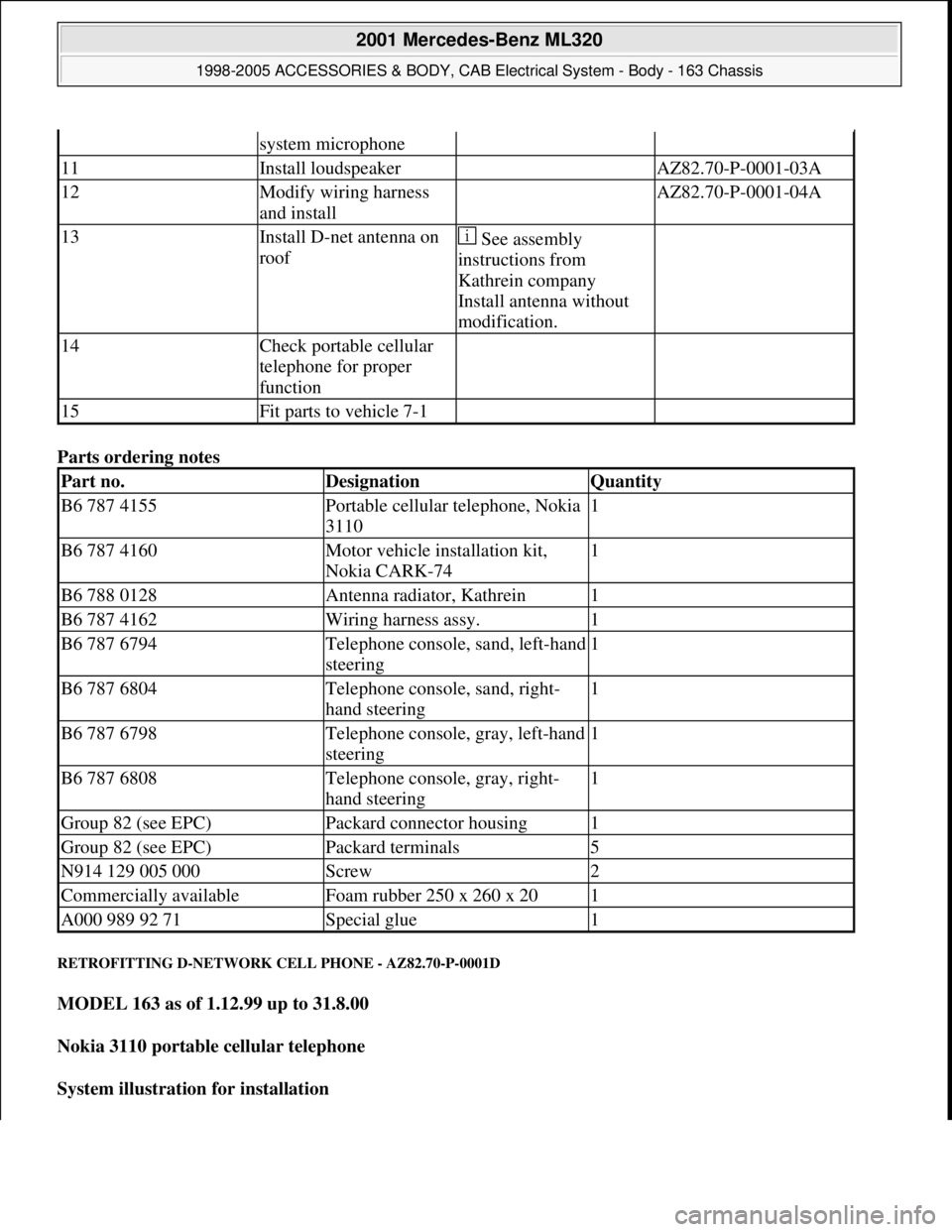
Parts ordering notes
RETROFITTING D-NETWORK CELL PHONE - AZ82.70-P-0001D
MODEL 163 as of 1.12.99 up to 31.8.00
Nokia 3110 portable cellular telephone
System illustration for installation
system microphone
11Install loudspeaker AZ82.70-P-0001-03A
12Modify wiring harness
and install AZ82.70-P-0001-04A
13Install D-net antenna on
roof See assembly
instructions from
Kathrein company
Install antenna without
modification.
14Check portable cellular
telephone for proper
function
15Fit parts to vehicle 7-1
Part no.DesignationQuantity
B6 787 4155Portable cellular telephone, Nokia
31101
B6 787 4160Motor vehicle installation kit,
Nokia CARK-741
B6 788 0128Antenna radiator, Kathrein1
B6 787 4162Wiring harness assy.1
B6 787 6794Telephone console, sand, left-hand
steering1
B6 787 6804Telephone console, sand, right-
hand steering1
B6 787 6798Telephone console, gray, left-hand
steering1
B6 787 6808Telephone console, gray, right-
hand steering1
Group 82 (see EPC)Packard connector housing1
Group 82 (see EPC)Packard terminals5
N914 129 005 000Screw2
Commercially availableFoam rubber 250 x 260 x 201
A000 989 92 71Special glue1
2001 Mercedes-Benz ML320
1998-2005 ACCESSORIES & BODY, CAB Electrical System - Body - 163 Chassis
me
Saturday, October 02, 2010 3:30:14 PMPage 444 © 2006 Mitchell Repair Information Company, LLC.
Page 1941 of 4133
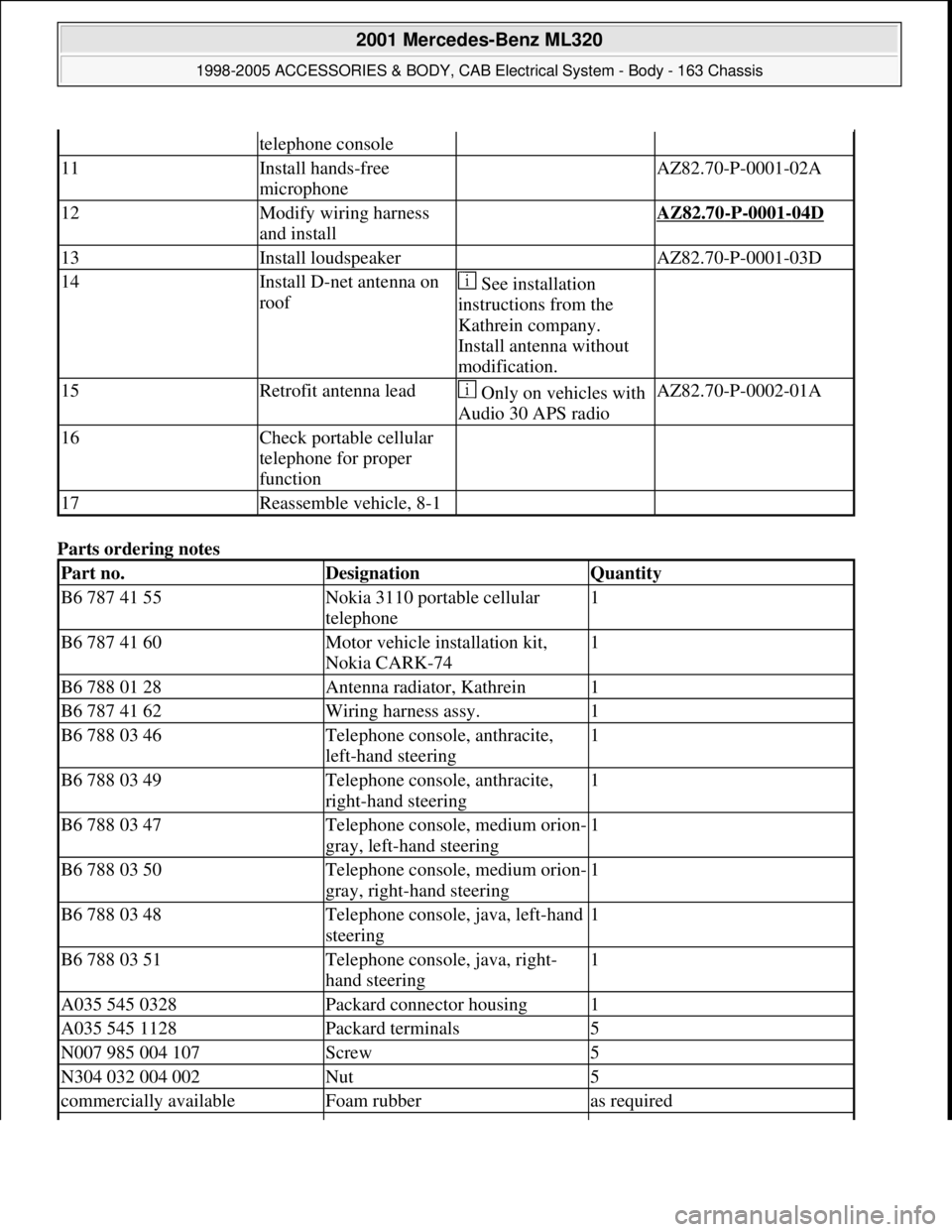
Parts ordering notes
telephone console
11Install hands-free
microphone AZ82.70-P-0001-02A
12Modify wiring harness
and install AZ82.70-P-0001-04D
13Install loudspeaker AZ82.70-P-0001-03D
14Install D-net antenna on
roof See installation
instructions from the
Kathrein company.
Install antenna without
modification.
15Retrofit antenna lead Only on vehicles with
Audio 30 APS radioAZ82.70-P-0002-01A
16Check portable cellular
telephone for proper
function
17Reassemble vehicle, 8-1
Part no.DesignationQuantity
B6 787 41 55Nokia 3110 portable cellular
telephone1
B6 787 41 60Motor vehicle installation kit,
Nokia CARK-741
B6 788 01 28Antenna radiator, Kathrein1
B6 787 41 62Wiring harness assy.1
B6 788 03 46Telephone console, anthracite,
left-hand steering1
B6 788 03 49Telephone console, anthracite,
right-hand steering1
B6 788 03 47Telephone console, medium orion-
gray, left-hand steering1
B6 788 03 50Telephone console, medium orion-
gray, right-hand steering1
B6 788 03 48Telephone console, java, left-hand
steering1
B6 788 03 51Telephone console, java, right-
hand steering1
A035 545 0328Packard connector housing1
A035 545 1128Packard terminals5
N007 985 004 107Screw5
N304 032 004 002Nut5
commercially availableFoam rubberas required
2001 Mercedes-Benz ML320
1998-2005 ACCESSORIES & BODY, CAB Electrical System - Body - 163 Chassis
me
Saturday, October 02, 2010 3:30:14 PMPage 446 © 2006 Mitchell Repair Information Company, LLC.