Page 1715 of 4133
(A2/56)
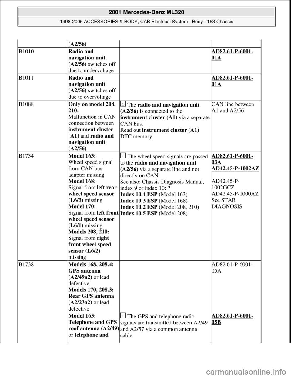
B1010Radio and
navigation unit
(A2/56) switches off
due to undervoltage AD82.61-P-6001-
01A
B1011Radio and
navigation unit
(A2/56) switches off
due to overvoltage AD82.61-P-6001-
01A
B1088Only on model 208,
210:
Malfunction in CAN
connection between
instrument cluster
(A1) and radio and
navigation unit
(A2/56) The radio and navigation unit
(A2/56) is connected to the
instrument cluster (A1)via a separate
CAN bus.
Read out instrument cluster (A1)
DTC memoryCAN line between
A1 and A2/56
B1734Model 163:
Wheel speed signal
from CAN bus
adapter missing
Model 168:
Signal from left rear
wheel speed sensor
(L6/3) missing
Model 170:
Signal from left front
wheel speed sensor
(L6/1) missing
Models 208, 210:
Signal from right
front wheel speed
sensor (L6/2)
missing The wheel speed signals are passed
to the radio and navigation unit
(A2/56) via a separate line and not
directly on CAN.
See also: Chassis Diagnosis Manual,
index 9 or index 10: ?
Index 10.4 ESP (Model 163)
Index 10.3 ESP (Model 168)
Index 10.2 ESP (Model 208, 210)
Index 10.5 ESP (Model 208)AD82.61-P-6001-
03A
AD42.45
-P-1002AZ
AD42.45-P-
1002GCZ
AD42.45-P-1000AZ
See STAR
DIAGNOSIS
B1738Models 168, 208.4:
GPS antenna
(A2/49a2) or lead
defective
Models 170, 208.3:
Rear GPS antenna
(A2/23a2) or lead
defective AD82.61-P-6001-
05A
Model 163:
Telephone and GPS
roof antenna (A2/49)
or telephone and The GPS and telephone radio
signals are transmitted between A2/49
and A2/57 via a common antenna
cable.AD82.61-P-6001-
05B
2001 Mercedes-Benz ML320
1998-2005 ACCESSORIES & BODY, CAB Electrical System - Body - 163 Chassis
me
Saturday, October 02, 2010 3:30:08 PMPage 220 © 2006 Mitchell Repair Information Company, LLC.
Page 1717 of 4133
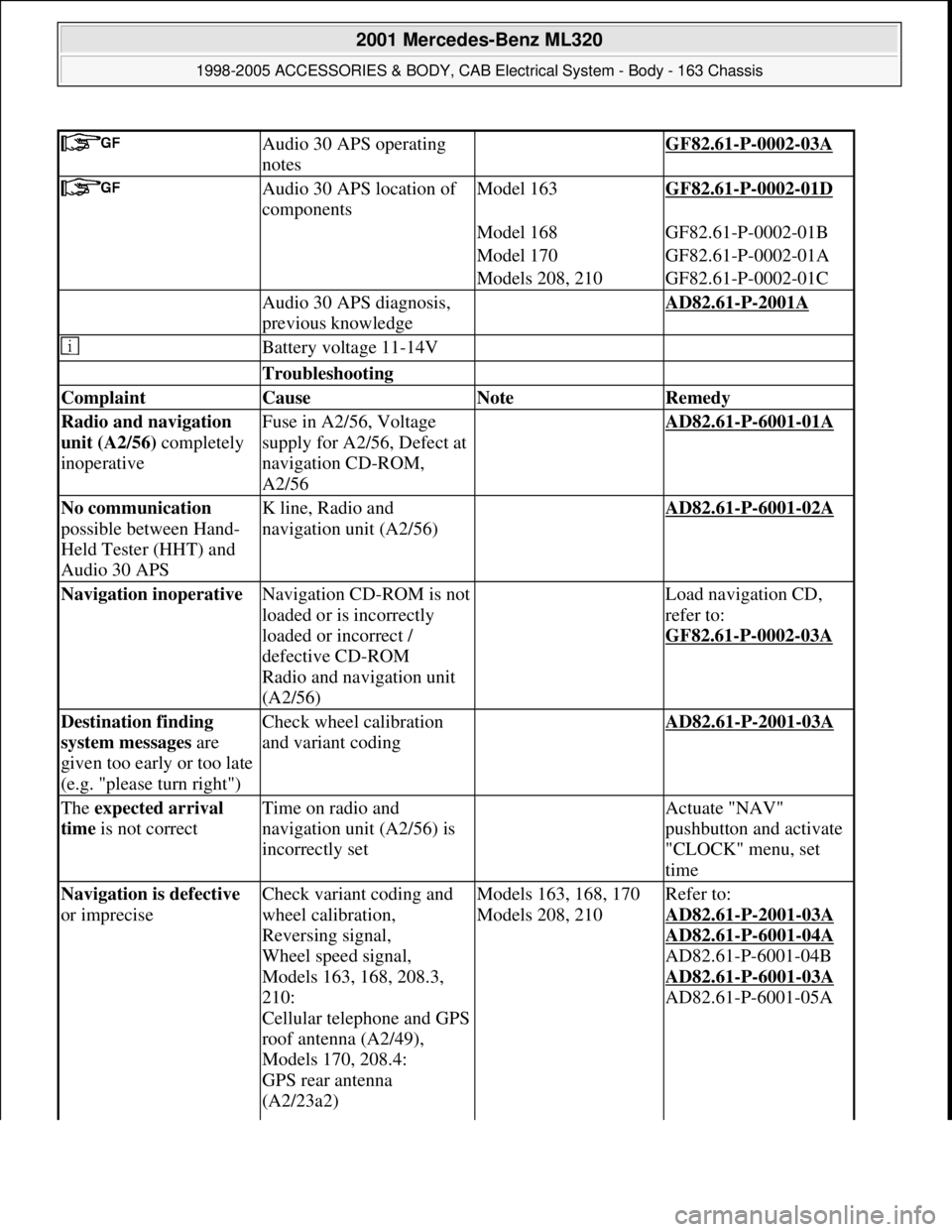
Audio 30 APS operating
notes GF82.61-P-0002-03A
Audio 30 APS location of
componentsModel 163GF82.61-P-0002-01D
Model 168GF82.61-P-0002-01B
Model 170GF82.61-P-0002-01A
Models 208, 210GF82.61-P-0002-01C
Audio 30 APS diagnosis,
previous knowledge AD82.61-P-2001A
Battery voltage 11-14V
Troubleshooting
Complaint Cause Note Remedy
Radio and navigation
unit (A2/56) completely
inoperativeFuse in A2/56, Voltage
supply for A2/56, Defect at
navigation CD-ROM,
A2/56 AD82.61-P-6001-01A
No communication
possible between Hand-
Held Tester (HHT) and
Audio 30 APSK line, Radio and
navigation unit (A2/56) AD82.61-P-6001-02A
Navigation inoperative Navigation CD-ROM is not
loaded or is incorrectly
loaded or incorrect /
defective CD-ROM
Radio and navigation unit
(A2/56) Load navigation CD,
refer to:
GF82.61
-P-0002-03A
Destination finding
system messages are
given too early or too late
(e.g. "please turn right")Check wheel calibration
and variant coding AD82.61-P-2001-03A
The expected arrival
time is not correctTime on radio and
navigation unit (A2/56) is
incorrectly set Actuate "NAV"
pushbutton and activate
"CLOCK" menu, set
time
Navigation is defective
or impreciseCheck variant coding and
wheel calibration,
Reversing signal,
Wheel speed signal,
Models 163, 168, 208.3,
210:
Cellular telephone and GPS
roof antenna (A2/49),
Models 170, 208.4:
GPS rear antenna
(A2/23a2) Models 163, 168, 170
Models 208, 210Refer to:
AD82.61
-P-2001-03A
AD82.61
-P-6001-04A
AD82.61-P-6001-04B
AD82.61
-P-6001-03A
AD82.61-P-6001-05A
2001 Mercedes-Benz ML320
1998-2005 ACCESSORIES & BODY, CAB Electrical System - Body - 163 Chassis
me
Saturday, October 02, 2010 3:30:08 PMPage 222 © 2006 Mitchell Repair Information Company, LLC.
Page 1718 of 4133
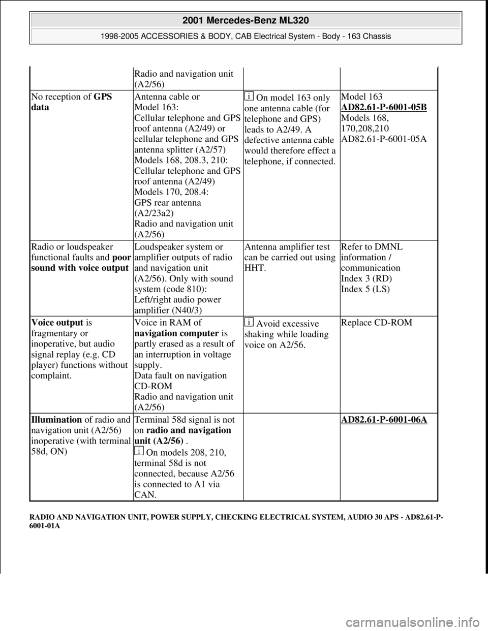
RADIO AND NAVIGATION UNIT, POWER SUPPLY, CHECKING ELECTRICAL SYSTEM, AUDIO 30 APS - AD82.61-P-
6001-01A
Radio and navigation unit
(A2/56)
No reception of GPS
data Antenna cable or
Model 163:
Cellular telephone and GPS
roof antenna (A2/49) or
cellular telephone and GPS
antenna splitter (A2/57)
Models 168, 208.3, 210:
Cellular telephone and GPS
roof antenna (A2/49)
Models 170, 208.4:
GPS rear antenna
(A2/23a2)
Radio and navigation unit
(A2/56) On model 163 only
one antenna cable (for
telephone and GPS)
leads to A2/49. A
defective antenna cable
would therefore effect a
telephone, if connected.Model 163
AD82.61
-P-6001-05B
Models 168,
170,208,210
AD82.61-P-6001-05A
Radio or loudspeaker
functional faults and poor
sound with voice output Loudspeaker system or
amplifier outputs of radio
and navigation unit
(A2/56). Only with sound
system (code 810):
Left/right audio power
amplifier (N40/3)Antenna amplifier test
can be carried out using
HHT.Refer to DMNL
information /
communication
Index 3 (RD)
Index 5 (LS)
Voice output is
fragmentary or
inoperative, but audio
signal replay (e.g. CD
player) functions without
complaint.Voice in RAM of
navigation computer is
partly erased as a result of
an interruption in voltage
supply.
Data fault on navigation
CD-ROM
Radio and navigation unit
(A2/56) Avoid excessive
shaking while loading
voice on A2/56.Replace CD-ROM
Illumination of radio and
navigation unit (A2/56)
inoperative (with terminal
58d, ON)Terminal 58d signal is not
on radio and navigation
unit (A2/56) .
On models 208, 210,
terminal 58d is not
connected, because A2/56
is connected to A1 via
CAN. AD82.61-P-6001-06A
2001 Mercedes-Benz ML320
1998-2005 ACCESSORIES & BODY, CAB Electrical System - Body - 163 Chassis
me
Saturday, October 02, 2010 3:30:08 PMPage 223 © 2006 Mitchell Repair Information Company, LLC.
Page 1767 of 4133
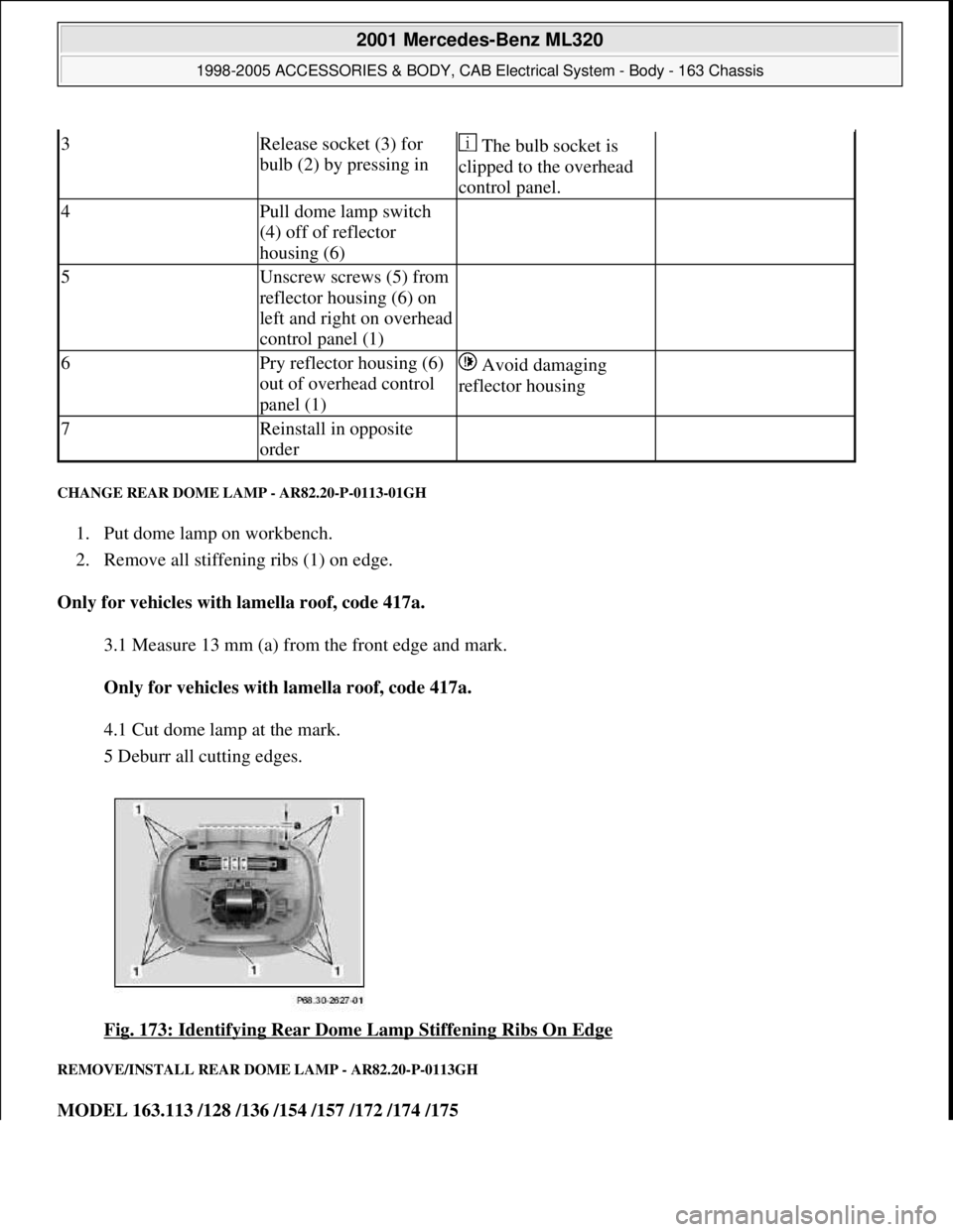
CHANGE REAR DOME LAMP - AR82.20-P-0113-01GH
1. Put dome lamp on workbench.
2. Remove all stiffening ribs (1) on edge.
Only for vehicles with lamella roof, code 417a.
3.1 Measure 13 mm (a) from the front edge and mark.
Only for vehicles with lamella roof, code 417a.
4.1 Cut dome lamp at the mark.
5 Deburr all cutting edges.
Fig. 173: Identifying Rear Dome Lamp Stiffening Ribs On Edge
REMOVE/INSTALL REAR DOME LAMP - AR82.20-P-0113GH
MODEL 163.113 /128 /136 /154 /157 /172 /174 /175
3Release socket (3) for
bulb (2) by pressing in The bulb socket is
clipped to the overhead
control panel.
4Pull dome lamp switch
(4) off of reflector
housing (6)
5Unscrew screws (5) from
reflector housing (6) on
left and right on overhead
control panel (1)
6Pry reflector housing (6)
out of overhead control
panel (1) Avoid damaging
reflector housing
7Reinstall in opposite
order
2001 Mercedes-Benz ML320
1998-2005 ACCESSORIES & BODY, CAB Electrical System - Body - 163 Chassis
me
Saturday, October 02, 2010 3:30:09 PMPage 272 © 2006 Mitchell Repair Information Company, LLC.
Page 1768 of 4133
Shown on model 163 without Parktronic system (PTS), code 220a
Fig. 174: Identifying Rear Dome Lamp Components
Remove/Install
1Prize off glass
cover (1) of the
rear interior lamp
(E15/3) and fold up
until it reaches the
limit stop
2.1Disconnect
connector from
Parktronic system
warning display Only with Parktronic system (PTS), code
220a.
3Remove rear
interior lamp
(E15/3) from
inside roof lining For removal pull dome lamp on rear
housing edge downward and simultaneously
forward.
4Remove connector
(2) from rear
interior lamp
(E15/3)
5Install in the
reverse order Installation: If dome lamp is replaced in
models 163.113 /128 /136 /154 /172 /174 /175
2001 Mercedes-Benz ML320
1998-2005 ACCESSORIES & BODY, CAB Electrical System - Body - 163 Chassis
me
Saturday, October 02, 2010 3:30:09 PMPage 273 © 2006 Mitchell Repair Information Company, LLC.
Page 1769 of 4133
REMOVE/INSTALL FRONT OVERHEAD CONTROL PANEL - AR82.20-P-1100GH
MODEL 163.113 /128 /136 /154 /157 /172 /174 /175
Fig. 175: Identifying Front Overhead Control Panel Components
without Parktronic system (PTS), code 220a
up to vehicle identification number
A346574: ?
Changing dome lamp in the rearAR82.20-P-0113-
01GH
Changing dome
lamp in the rear BT82.20-P-0001-
03GH
Remove/install
1Remove garage door
opener flap (1) from
overhead control panel (2)
2Unclip cover (3) on the
sliding/tilting roof switch
(S13/2) 4 clips.
3Unclip glass covers (4)
from interior lights
4Unscrew screws (5)
2001 Mercedes-Benz ML320
1998-2005 ACCESSORIES & BODY, CAB Electrical System - Body - 163 Chassis
me
Saturday, October 02, 2010 3:30:09 PMPage 274 © 2006 Mitchell Repair Information Company, LLC.
Page 1770 of 4133
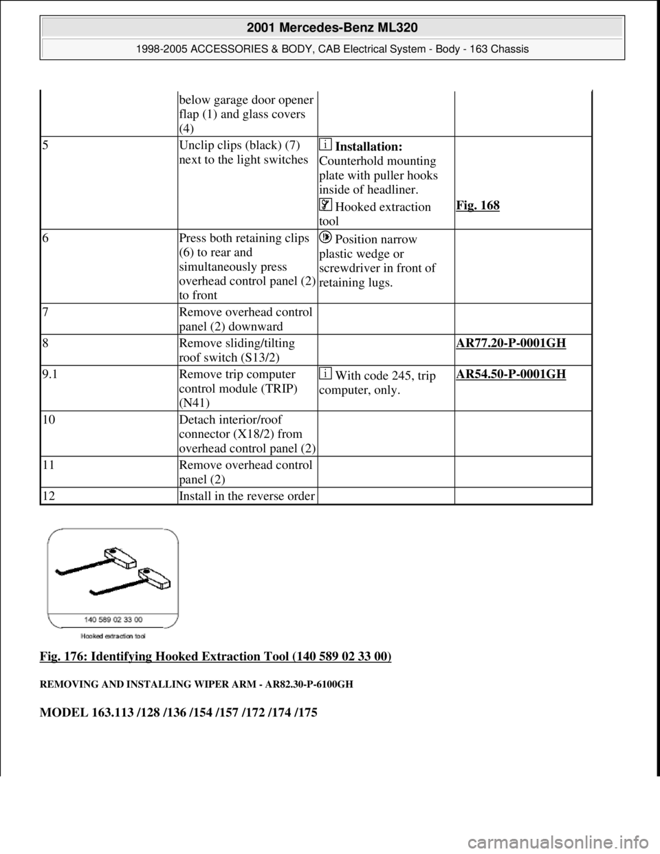
Fig. 176: Identifying Hooked Extraction Tool (140 589 02 33 00)
REMOVING AND INSTALLING WIPER ARM - AR82.30-P-6100GH
MODEL 163.113 /128 /136 /154 /157 /172 /174 /175
below garage door opener
flap (1) and glass covers
(4)
5Unclip clips (black) (7)
next to the light switches Installation:
Counterhold mounting
plate with puller hooks
inside of headliner.
Hooked extraction
toolFig. 168
6Press both retaining clips
(6) to rear and
simultaneously press
overhead control panel (2)
to front Position narrow
plastic wedge or
screwdriver in front of
retaining lugs.
7Remove overhead control
panel (2) downward
8Remove sliding/tilting
roof switch (S13/2) AR77.20-P-0001GH
9.1Remove trip computer
control module (TRIP)
(N41) With code 245, trip
computer, only.AR54.50-P-0001GH
10Detach interior/roof
connector (X18/2) from
overhead control panel (2)
11Remove overhead control
panel (2)
12Install in the reverse order
2001 Mercedes-Benz ML320
1998-2005 ACCESSORIES & BODY, CAB Electrical System - Body - 163 Chassis
me
Saturday, October 02, 2010 3:30:09 PMPage 275 © 2006 Mitchell Repair Information Company, LLC.
Page 1787 of 4133
CHECK MICROPHONE FOR SOUND AMPLIFIER - AR82.62-P-1110GH
MODELS 163.113 /154 /174 #A as of 289565, 163.128 /157 /175 with CODE (810) Sound system
Commercially available tools
REMOVING AND INSTALLING MICROPHONE - AR82.62-P-7700GH
MODELS 163.113 /154 /174 #A as of 289560, 163.113 #X as of 754620, 163.128 /157 /175 with CODE
(810) Sound system
with the antenna surface.
Special wrench (1) is
included in the
installation kit.
2Unscrew threaded sleeve
(3)
3Disconnect telephone and
GPS roof antenna (A2/49) Installation: Install
new rubber grommet (5).
Ensure that the grommet
is in the correct
installation position. No
longer use foam gasket
(4).
4Install in the reverse order
Inspect
1Connect STAR
DIAGNOSIS *WH58.30-Z-1048-13A
*WH58.30-Z-1052-13A
2Select Actual values in
menu SOUND - Sound
system
3Select Microphone test:
B25/6 (sound amplifier
microphone) Follow the
instructions on the screen
for every test in order to
determine the source of
fault. Carry out repair
against a separate order.
NumberDesignation
WH58.30-Z-1048-13ASTAR DIAGNOSIS diagnosis
system, Compact Passenger Car6511 1801 00
WH58.30-Z-1052-13ASTAR DIAGNOSIS 16-pin
connecting cable651 112 40 99
2001 Mercedes-Benz ML320
1998-2005 ACCESSORIES & BODY, CAB Electrical System - Body - 163 Chassis
me
Saturday, October 02, 2010 3:30:09 PMPage 292 © 2006 Mitchell Repair Information Company, LLC.