Page 1619 of 4133
Fig. 75: Identifying CD Player With Changer
GPS/CTEL ROOF ANTENNA, LOCATION - GF82.70-P-4111-01GH
Model 163
Location, illustration valid up to 31.08.01:
The CTEL and GPS roof antenna (A2/49) is mounted on the rear of the roof in the middle of the vehicle.
CD player with changer,
location GF82.64-P-3113-01GI
CD player with changer,
purposePlaying audio
compact discs (CD).
Changing CD's
contained in the
magazine
CD player with changer,
designCD changer
magazine for 6 CD's
Digital data bus
(D2B) interface
The installation position
of the CD changer
predefined by the factory
is vertical, however
another installation
location is also possible
by adapting the spring
location
CD player with changer,
function GF82.64-P-3113-02GI
2001 Mercedes-Benz ML320
1998-2005 ACCESSORIES & BODY, CAB Electrical System - Body - 163 Chassis
me
Saturday, October 02, 2010 3:30:06 PMPage 124 © 2006 Mitchell Repair Information Company, LLC.
Page 1620 of 4133
Fig. 76: Identifying CTEL And GPS Roof Antenna (31.08.01)
Location, illustrati on valid as of 01.09.01:
The CTEL and GPS roof antenna (A2/49) is moun ted in the rear area of the vehicle roof.
Fig. 77: Identifying CTEL And GPS Roof Antenna (01.09.01)
Illustration shows model 163 up to 31.8.01 :
2001 Mercedes-Benz ML320
1998-2005 ACCESSORIES & BODY, CAB Electr ical System - Body - 163 Chassis
me
Saturday, October 02, 2010 3:30:06 PMPage 125 © 2006 Mitchell Repair Information Company, LLC.
Page 1621 of 4133
Fig. 78: Identifying CTEL And GPS Roof Antenna (31.8.01)
Illustration shows model 163 as of 01.9.01 :
Fig. 79: Identifying CTEL And GPS Roof Antenna (01.9.01)
GPS/CTEL ROOF ANTENNA, DESIGN - GF82.70-P-4111-03GH
Model 163 as of 01.9.01
2001 Mercedes-Benz ML320
1998-2005 ACCESSORIES & BODY, CAB Electr ical System - Body - 163 Chassis
me
Saturday, October 02, 2010 3:30:06 PMPage 126 © 2006 Mitchell Repair Information Company, LLC.
Page 1622 of 4133
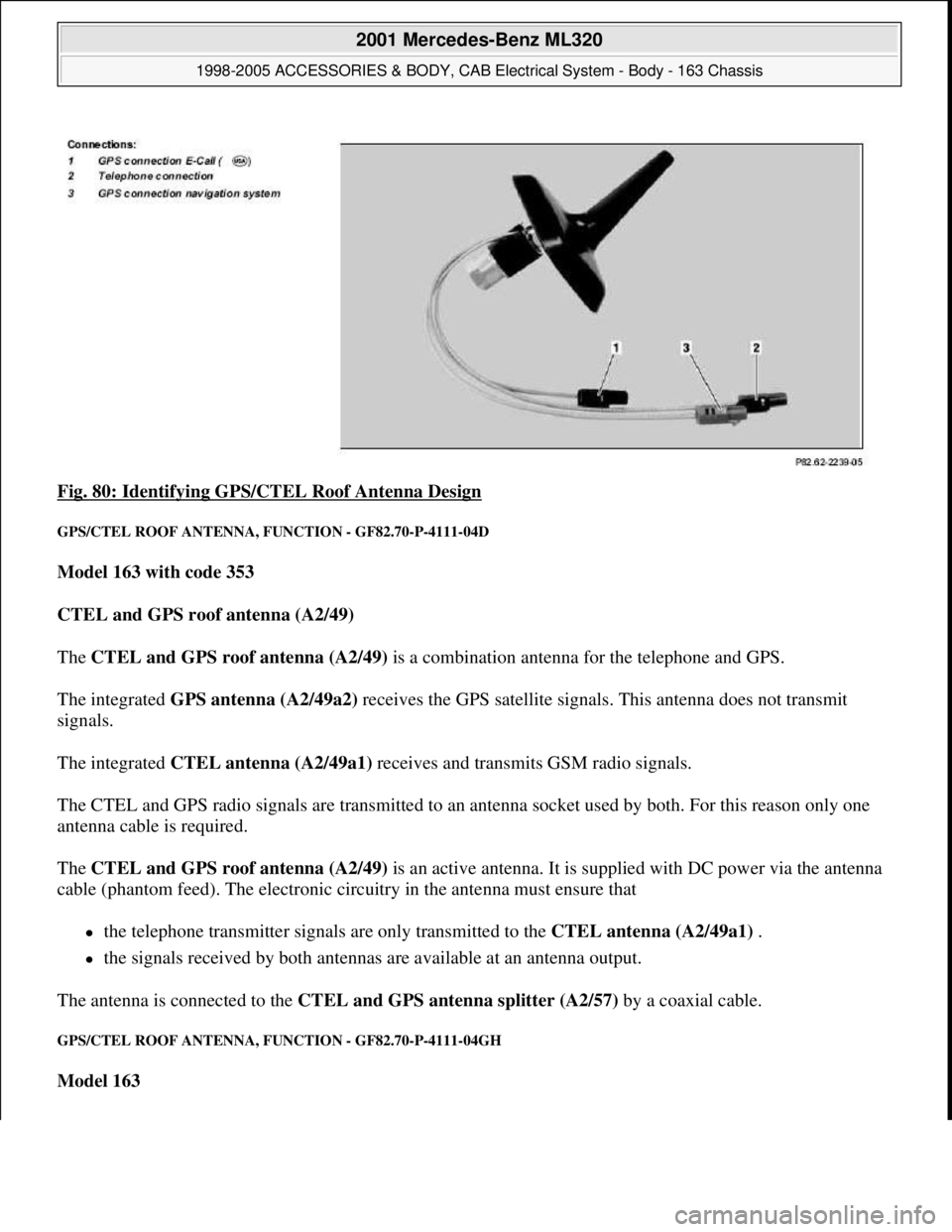
Fig. 80: Identifying GPS/CTEL Roof Antenna Design
GPS/CTEL ROOF ANTENNA, FUNCTION - GF82.70-P-4111-04D
Model 163 with code 353
CTEL and GPS roof antenna (A2/49)
The CTEL and GPS roof antenna (A2/49) is a combination antenna for the telephone and GPS.
The integrated GPS antenna (A2/49a2) receives the GPS satellite signals. This antenna does not transmit
signals.
The integrated CTEL antenna (A2/49a1) receives and transmits GSM radio signals.
The CTEL and GPS radio signals are transmitted to an antenna socket used by both. For this reason only one
antenna cable is required.
The CTEL and GPS roof antenna (A2/49) is an active antenna. It is supplied with DC power via the antenna
cable (phantom feed). The electronic circuitry in the antenna must ensure that
the telephone transmitter signals are only transmitted to the CTEL antenna (A2/49a1) .
the signals received by both antennas are available at an antenna output.
The antenna is connected to the CTEL and GPS antenna splitter (A2/57) by a coaxial cable.
GPS/CTEL ROOF ANTENNA, FUNCTION - GF82.70-P-4111-04GH
Model 163
2001 Mercedes-Benz ML320
1998-2005 ACCESSORIES & BODY, CAB Electrical System - Body - 163 Chassis
me
Saturday, October 02, 2010 3:30:06 PMPage 127 © 2006 Mitchell Repair Information Company, LLC.
Page 1623 of 4133
Function up to 31.8.01
The GPS/CTEL roof antenna (A2/49) is a combination antenna for telephone and GPS.
The CTEL and GPS roof antenna (A2/49) receives the GPS satellite signals. No GPS signals are transmitted
over this range of the antenna.
The CTEL and GPS roof antenna (A2/49) receives and transmits the GSM radio signals.
The radio signals for CTEL and GPS are transmitted to the CTEL and GPS antenna splitter (A2/57) via a
common antenna cable.
The CTEL and GPS roof antenna (A2/49) is an active antenna .
It is supplied with direct voltage via the antenna cable ( phantom feed ). The electronics in the antenna must
ensure that the
transmission signals of the cellular telephone are transmitted by the CTEL and GPS roof antenna
(A2/49)
the received signals of both antennas are made available to an antenna output.
The antenna is linked via a coaxial cable to the CTEL and GPS antenna splitter (A2/57) .
Function as of 01.09.01
The CTEL and GPS roof antenna (A2/49) is a new version of the combination antenna for CTEL and GPS.
It has an integrated antenna splitter and an antenna amplifier, which eliminates the need for the CTEL and
GPS antenna splitter (A2/57) . splitter
The CTEL and GPS roof antenna (A2/49) has connections for
Cellular telephone,
GPS navigation system and
GPS E-Call ( )
GPS/TELEPHONE ROOF ANTENNA, LOCATION/TASK/DESIGN/FUNCTION - GF82.70-P-4111A
MODELS 140, 210 up to 31.5.98 with CODE (348) TELE AID emergency call system
MODELS 129, 202, 208.3, 210 as of 6/198, 220 with CODE (347) TELE AID emergency call system (D2B)
MODEL 140 as of 1.1.98, 168, 202, 208.3, 210.0 as of 1.1.98, 210.2 with CODE (351) Auto pilot system
(APS)
MODELS 163,168, 208.3, 210 with CODE (353) Audio 30 APS
2001 Mercedes-Benz ML320
1998-2005 ACCESSORIES & BODY, CAB Electrical System - Body - 163 Chassis
me
Saturday, October 02, 2010 3:30:06 PMPage 128 © 2006 Mitchell Repair Information Company, LLC.
Page 1624 of 4133
MODELS 163, 208.3, 210, 220 with CODE (352a) COMAND operating and display system with CODE
(353) Audio 30 APS with CODE (853) MB standard CTEL telephone with CODE (854) MB portable
CTEL telephone with CODE (855) TELE AID
MODEL 163 with CODE (522) Modular control system (MCS) Radio USA
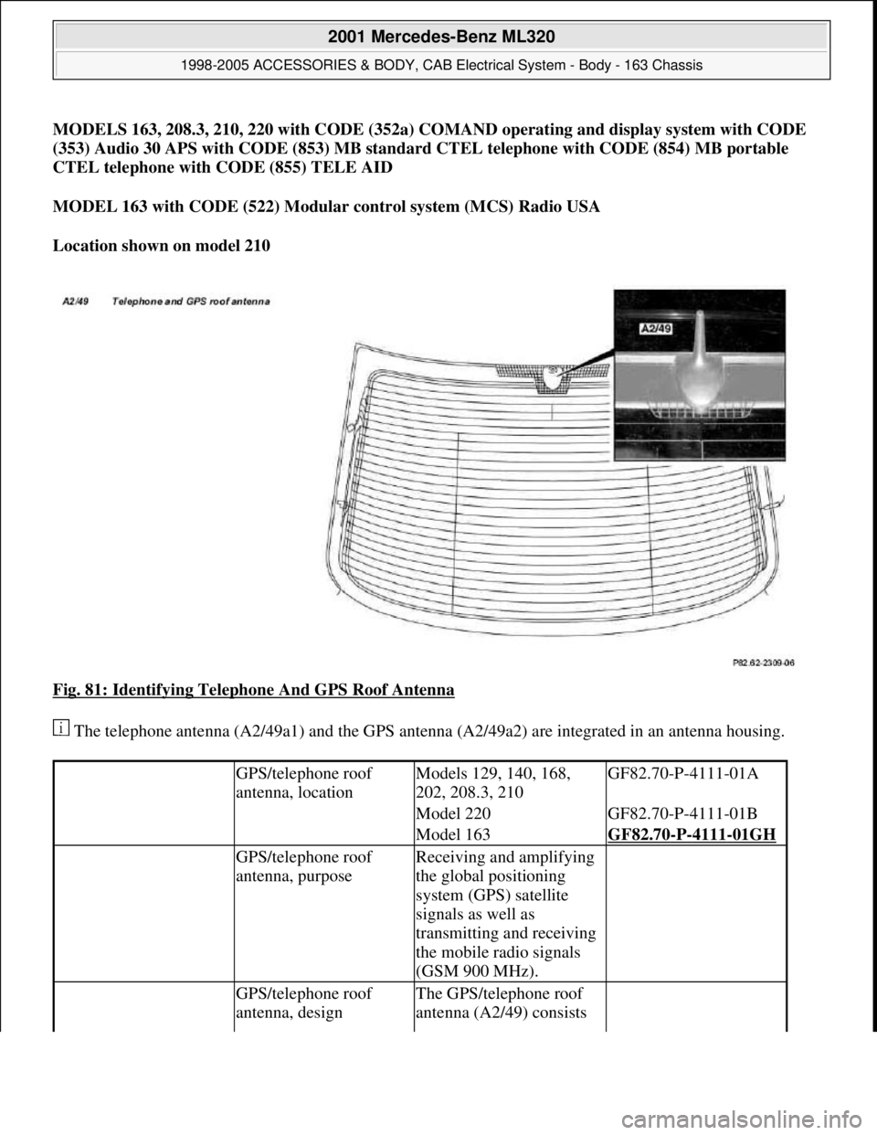
Location shown on model 210
Fig. 81: Identifying Telephone And GPS Roof Antenna
The telephone antenna (A2/49a1) and the GPS antenna (A2/49a2) are integrated in an antenna housing.
GPS/telephone roof
antenna, locationModels 129, 140, 168,
202, 208.3, 210GF82.70-P-4111-01A
Model 220GF82.70-P-4111-01B
Model 163GF82.70-P-4111-01GH
GPS/telephone roof
antenna, purposeReceiving and amplifying
the global positioning
system (GPS) satellite
signals as well as
transmitting and receiving
the mobile radio signals
(GSM 900 MHz).
GPS/telephone roof
antenna, designThe GPS/telephone roof
antenna (A2/49) consists
2001 Mercedes-Benz ML320
1998-2005 ACCESSORIES & BODY, CAB Electrical System - Body - 163 Chassis
me
Saturday, October 02, 2010 3:30:06 PMPage 129 © 2006 Mitchell Repair Information Company, LLC.
Page 1625 of 4133
MODULAR CONTROL SYSTEM (MCS), FUNCTION - GF82.85-P-0011GI
MODEL 163 as of 1.9.01 with CODE (522) Modular control system (MCS) radio USA with CODE (357)
Navigation system - additional unit with CODE (818b) Single CD player - additional unit with CODE
(819) 6-disk CD changer in trunk with CODE (491) U.S. version
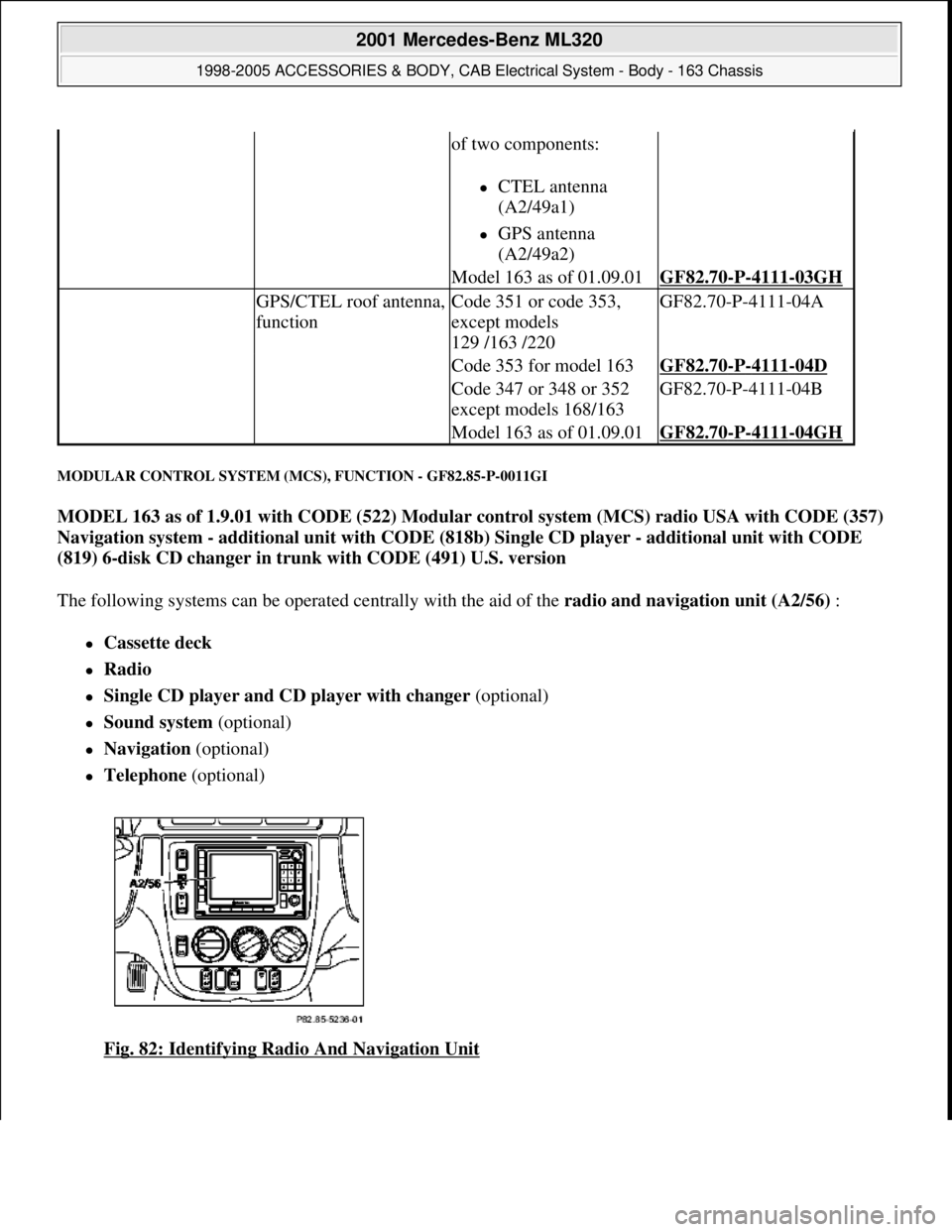
The following systems can be operated centrally with the aid of the radio and navigation unit (A2/56) :
Cassette deck
Radio
Single CD player and CD player with changer (optional)
Sound system (optional)
Navigation (optional)
Telephone (optional)
Fig. 82: Identifying Radio And Navigation Unit
of two components:
CTEL antenna
(A2/49a1)
GPS antenna
(A2/49a2)
Model 163 as of 01.09.01GF82.70-P-4111-03GH
GPS/CTEL roof antenna,
functionCode 351 or code 353,
except models
129 /163 /220GF82.70-P-4111-04A
Code 353 for model 163GF82.70-P-4111-04D
Code 347 or 348 or 352
except models 168/163GF82.70-P-4111-04B
Model 163 as of 01.09.01GF82.70-P-4111-04GH
2001 Mercedes-Benz ML320
1998-2005 ACCESSORIES & BODY, CAB Electrical System - Body - 163 Chassis
me
Saturday, October 02, 2010 3:30:06 PMPage 130 © 2006 Mitchell Repair Information Company, LLC.
Page 1632 of 4133
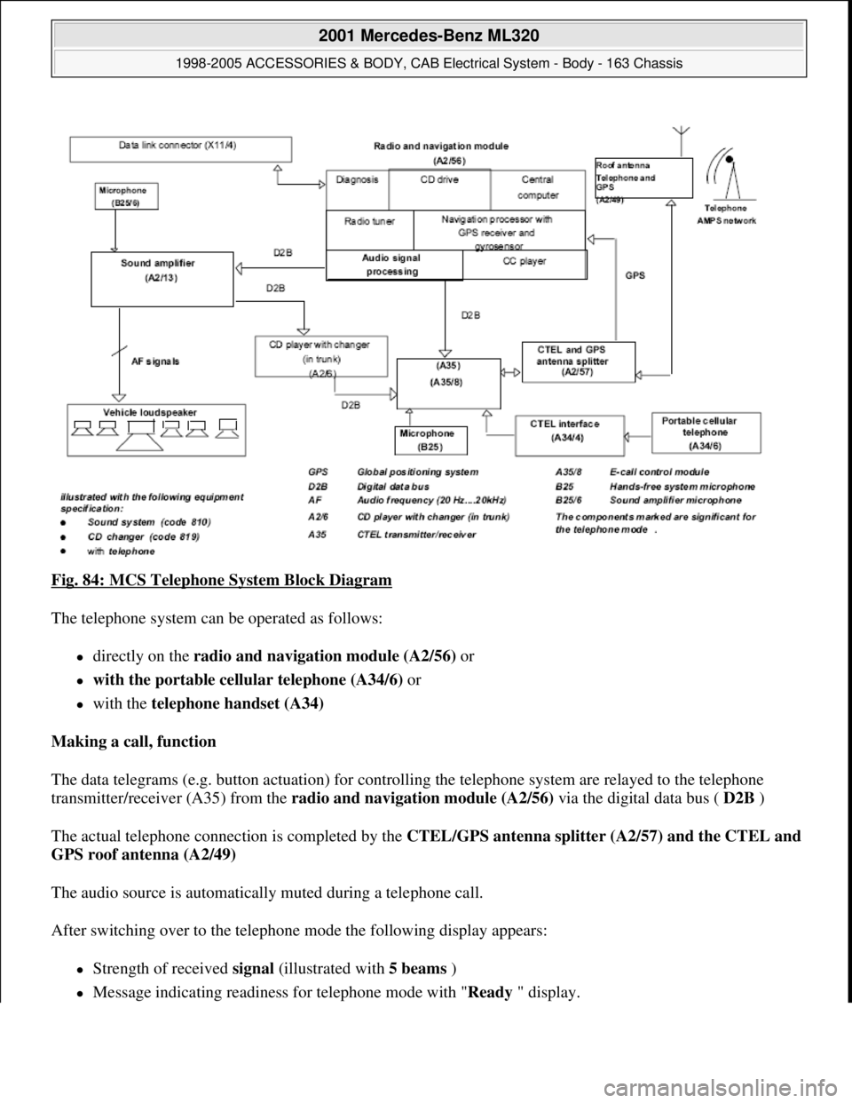
Fig. 84: MCS Telephone System Block Diagram
The telephone system can be operated as follows:
directly on the radio and navigation module (A2/56) or
with the portable cellular telephone (A34/6) or
with the telephone handset (A34)
Making a call, function
The data telegrams (e.g. button actuation) for controlling the telephone system are relayed to the telephone
transmitter/receiver (A35) from the radio and navigation module (A2/56) via the digital data bus ( D2B )
The actual telephone connection is completed by the CTEL/GPS antenna splitter (A2/57) and the CTEL and
GPS roof antenna (A2/49)
The audio source is automatically muted during a telephone call.
After switching over to the telephone mode the following display appears:
Strength of received signal (illustrated with 5 beams )
Message indicating readiness for telephone mode with "Ready" display.
2001 Mercedes-Benz ML320
1998-2005 ACCESSORIES & BODY, CAB Electrical System - Body - 163 Chassis
me
Saturday, October 02, 2010 3:30:06 PMPage 137 © 2006 Mitchell Repair Information Company, LLC.