1997 MERCEDES-BENZ ML500 roof
[x] Cancel search: roofPage 2042 of 4133
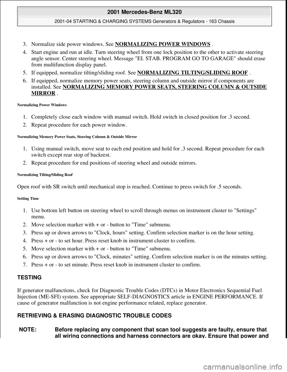
3. Normalize side power windows. See NORMALIZING POWER WINDOWS .
4. Start engine and run at idle. Turn steering wheel from one lock position to the other to activate steering
angle sensor. Center steering wheel. Message "EI. STAB. PROGRAM GO TO GARAGE" should erase
from multifunction display panel.
5. If equipped, normalize tilting/sliding roof. See NORMALIZING TILTING/SLIDING ROOF
.
6. If equipped, normalize memory power seats, steering column and outside mirror if components are
installed. See NORMALIZING MEMORY POWER SEATS, STEERING COLUMN & OUTSIDE
MIRROR .
Normalizing Power Windows
1. Completely close each window with manual switch. Hold switch in closed position for .3 second.
2. Repeat procedure for each power window.
Normalizing Memory Power Seats, Steering Column & Outside Mirror
1. Using manual switch, move seat to each end position and hold for .3 second. Repeat procedure for each
switch except rear stop of backrest.
2. Repeat procedure for end positions of steering wheel and outside mirrors.
Normalizing Tilting/Sliding Roof
Open roof with SR switch until mechanical stop is reached. Continue to press switch for .5 seconds.
Setting Time
1. Use bottom left button on steering wheel to scroll through menus on instrument cluster to "Settings"
menu.
2. Move selection marker with + or - button to "Time" submenu.
3. Press up or down arrows to "Clock, hours" setting. Confirm selection marker is on the hour setting.
4. Press + or - to set hour. Press reset knob in instrument cluster to confirm.
5. Move selection marker with + or - button to "Time" submenu.
6. Press up or down arrows to "Clock, minutes" setting. Confirm selection marker is on the minutes setting.
7. Press + or - to set minute. Press reset knob in instrument cluster to confirm.
TESTING
If generator malfunctions, check for Diagnostic Trouble Codes (DTCs) in Motor Electronics Sequential Fuel
Injection (ME-SFI) system. See appropriate SELF-DIAGNOSTICS article in ENGINE PERFORMANCE. If
cause of generator malfunction is not engine performance related, replace generator.
RETRIEVING & ERASING DIAGNOSTIC TROUBLE CODES
NOTE: Before replacing any component that scan tool suggests are faulty, ensure that
all wiring connections and harness connectors are okay. Ensure that power and
2001 Mercedes-Benz ML320
2001-04 STARTING & CHARGING SYSTEMS Generators & Regulators - 163 Chassis
me
Saturday, October 02, 2010 3:20:32 PMPage 8 © 2006 Mitchell Repair Information Company, LLC.
Page 2063 of 4133

GF77.20-P-2002GH
Closing sliding /pop-up roof, function
19.2.97
MODEL
163 with CODE (414a) Electric glass sliding/pop-up roof
Function prerequisites
D
Voltage not too low or too high
D
Switch-on conditions for convenience control fulfilled
Function
The sliding roof and pop-up roof can be closed by pressing the
switch (SR, S13/2)
. The sliding/pop-up roof can only be closed by
continuously pressing the
switch (SR, S13/2)
.
The express close function is not available for safety reasons.
If the sliding/pop-up roof has not been synchronized, it opens only in
the pop-up roof direction each time the
switch (SR, S13/2) is
actuated. Upon reaching its end position, i.e. before the pop-up roof
is completely open,
synchronization
is accomplished.
After successful synchronization, the sliding/pop-up roof can then be
controlled without limitations.
Vehicles
up to 11.99:
The power for the
sliding/pop-up roof (M12)
is supplied via a
fuse directly to c. 30.
The power for the
switch (SR, S13/2)
is supplied via the
convenience relay (F1k14)
, which is actuated by the
all-activity
module (AAM, N10)
.
Vehicles
as of 12.99:
The power for the
sliding/pop-up roof (M12)
is supplied via a
fuse directly to c. 30. The power for the
switch (SHD, S13/2) is
supplied via a lead to the
extended-activity module (EAM,
N10/1) , this power is switched through only when the switch-on
conditions for the convenience control are fulfilled and the EAM is
coded accordingly.
Opening pop-up roof, function
GF77.20-P-2003GH
Opening sliding roof, function
GF77.20-P-2004GH
Synchronizing sliding /pop-up roof, function
GF77.20-P-3002GH
Sliding/pop-up roof, location/purpose/
design/function
GF77.20-P-4100GH
Convenience control
GF72.29-P-2002GH
All-activity module (AAM)
up to 11.99
GF54.21-P-4100GH
Extended-activity module, location/
purpose/design
as of 12.99
GF54.21-P-4107GK
Copyright DaimlerChrysler AG 04.08.2006 CD-Ausgabe G/10/04 . This WIS print-out will not be recorde
d by Modification services.
Page 1
Page 2067 of 4133

GF72.29-P-2002GH
Convenience control, function
7.4.97
MODEL
163
The convenience control allows the driver to operate the electrical
seat adjustment, the power windows, the electric vent windows, the
electric outside rearview mirror as well as the electric sliding/pop-up
roof or the electric lamella sliding roof
when the ignition is switched
off.
To achieve this, the all-activity module (AAM) (N10) switches to the
corresponding loads via the convenience relay (F1k14)
circuit 30 .
As of 12.99 the vehicle is equipped with its own convenience relay for
seat adjustment (relay 1, F2k1). In addition the status of the
convenience control via CAN is transmitted to the extended activity
module (EAM, N10/1).
Conditions for control actuation
On all-activity module (AAM) (N10) configured for
I
up
to
11.99:
The convenience actuation becomes active as soon as
D
Circuit 15 ON is recognized
When circuit 15 is switched off, the convenience actuation is
deactivated after a door is opened
Otherwise
The convenience actuation is active in the following cases:
D
Circuit 15c ON
D
A front door is open
D
The remote control key is removed, however, the doors are not
yet opened
In both cases the convenience actuation remains active for 5 min.
Switch-on condition for circuit 15c
When the remote control key is inserted into the ignition lock, circuit
15c is switched on when the key is turned out of the zero position.
Circuit 15c switches off only after the remote control key is removed
from the ignition lock
Electric seat adjustment without memory,
function
GF91.29-P-0003GH
Electric seat adjustment with memory, function
as of 12.99
GF91.29-P-0002GH
Convenience control, function
for electrical seat adjustment as of 12.99
GF91.29-P-2013GK
Power windows, function
GF72.29-P-0003GH
Power tilting/sliding roof (SR), function
GF77.20-P-0001GH
Electrically adjustable outside rearview
mirrors, function
GF88.79-P-0005GH
Electric vent windows, function
GF67.39-P-1000GH
Extended activity module,
location/purpose/design
as of 12.99
GF54.21-P-4107GK
Copyright DaimlerChrysler AG 04.08.2006 CD-Ausgabe G/10/04 . This WIS print-out will not be recorde
d by Modification services.
Page 1
Page 2068 of 4133
AR20.00-P-1142M
Drain, pour in coolant
8.11.99
ENGINE
612.963 in MODEL 163.113
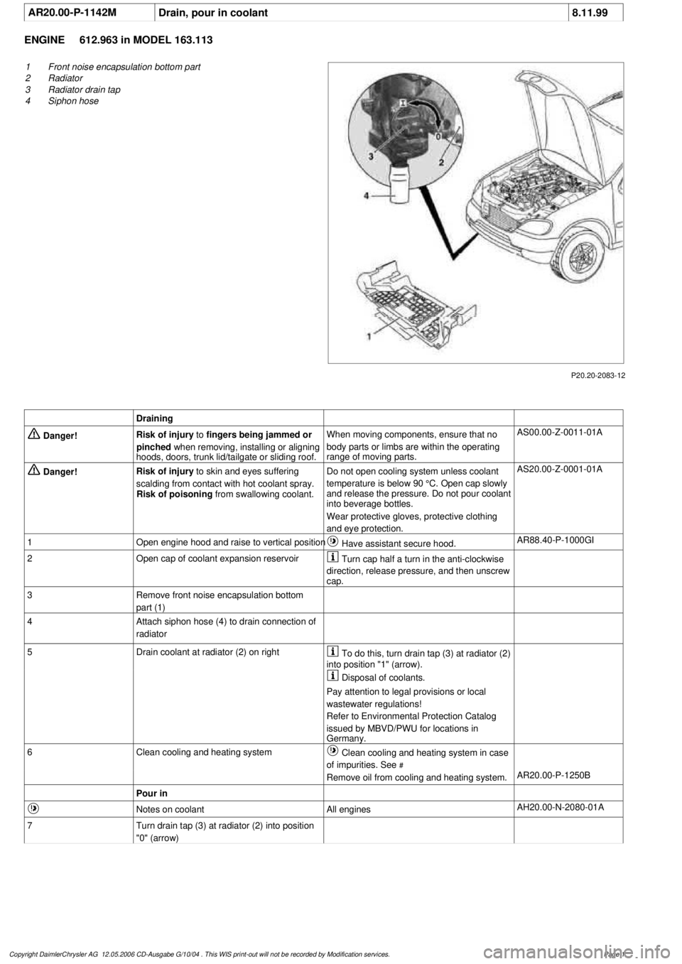
P20.20-2083-12
1
Front noise encapsulation bottom part
2
Radiator
3
Radiator drain tap
4
Siphon hose
Draining
Danger!
Risk of injury
to
fingers being jammed or
pinched
when removing, installing or aligning
hoods, doors, trunk lid/tailgate or sliding roof.
When moving components, ensure that no
body parts or limbs are within the operating
range of moving parts.
AS00.00-Z-0011-01A
Danger!
Risk of injury
to skin and eyes suffering
scalding from contact with hot coolant spray.
Risk of poisoning
from swallowing coolant.
Do not open cooling system unless coolant
temperature is below 90 °C. Open cap slowly
and release the pressure. Do not pour coolant
into beverage bottles.
Wear protective gloves, protective clothing
and eye protection.
AS20.00-Z-0001-01A
1
Open engine hood and raise to vertical position
Have assistant secure hood.
AR88.40-P-1000GI
2
Open cap of coolant expansion reservoir
Turn cap half a turn in the anti-clockwise
direction, release pressure, and then unscrew
cap.
3
Remove front noise encapsulation bottom
part (1)
4
Attach siphon hose (4) to drain connection of
radiator
5
Drain coolant at radiator (2) on right
To do this, turn drain tap (3) at radiator (2)
into position "1" (arrow).
Disposal of coolants.
Pay attention to legal provisions or local
wastewater regulations!
Refer to Environmental Protection Catalog
issued by MBVD/PWU for locations in
Germany.
6
Clean cooling and heating system
Clean cooling and heating system in case
of impurities. See
#
Remove oil from cooling and heating system.
AR20.00-P-1250B
Pour in
Notes on coolant
All engines
AH20.00-N-2080-01A
7
Turn drain tap (3) at radiator (2) into position
"0" (arrow)
Copyright DaimlerChrysler AG 12.05.2006 CD-Ausgabe G/10/04 . This WIS print-out will not be recorde
d by Modification services.
Page 1
Page 2075 of 4133
AR20.00-P-1142M
Drain, pour in coolant
8.11.99
ENGINE
612.963 in MODEL 163.113
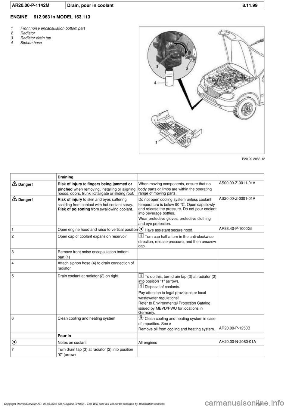
P20.20-2083-12
1
Front noise encapsulation bottom part
2
Radiator
3
Radiator drain tap
4
Siphon hose
Draining
Danger!
Risk of injury
to
fingers being jammed or
pinched
when removing, installing or aligning
hoods, doors, trunk lid/tailgate or sliding roof.
When moving components, ensure that no
body parts or limbs are within the operating
range of moving parts.
AS00.00-Z-0011-01A
Danger!
Risk of injury
to skin and eyes suffering
scalding from contact with hot coolant spray.
Risk of poisoning
from swallowing coolant.
Do not open cooling system unless coolant
temperature is below 90 °C. Open cap slowly
and release the pressure. Do not pour coolant
into beverage bottles.
Wear protective gloves, protective clothing
and eye protection.
AS20.00-Z-0001-01A
1
Open engine hood and raise to vertical position
Have assistant secure hood.
AR88.40-P-1000GI
2
Open cap of coolant expansion reservoir
Turn cap half a turn in the anti-clockwise
direction, release pressure, and then unscrew
cap.
3
Remove front noise encapsulation bottom
part (1)
4
Attach siphon hose (4) to drain connection of
radiator
5
Drain coolant at radiator (2) on right
To do this, turn drain tap (3) at radiator (2)
into position "1" (arrow).
Disposal of coolants.
Pay attention to legal provisions or local
wastewater regulations!
Refer to Environmental Protection Catalog
issued by MBVD/PWU for locations in
Germany.
6
Clean cooling and heating system
Clean cooling and heating system in case
of impurities. See
#
Remove oil from cooling and heating system.
AR20.00-P-1250B
Pour in
Notes on coolant
All engines
AH20.00-N-2080-01A
7
Turn drain tap (3) at radiator (2) into position
"0" (arrow)
Copyright DaimlerChrysler AG 28.05.2006 CD-Ausgabe G/10/04 . This WIS print-out will not be recorde
d by Modification services.
Page 1
Page 2139 of 4133

GF54.21-P-4106-01GH
Extended Activity Module - Task
n
The primary tasks of the Extended Activity Module (EAM, N10/1) are
as follows:
D
To control the door sill lights
D
To suppress the auto-dimming mirror function
D
To control the headlight cleaning system (HCS)
D
To control the rear window defroster
D
To control seat heating
D
To control the power supply via control console to tilt/sliding or
louvered sunroof switch
D
To control the PTC heater booster (R22/3)
D
To control the auxiliary fan (M4)
D
To read the cruise control switch (S40) and relay data to control
module (DAS, N73/1)
D
To read the contacts for wiper speed settings 1 and 2 on
combination switch (S4) for diagnosis.
To perform these tasks the Extended Activity Module (EAM, N10/1)
reads various signals and switch settings directly.
The Extended Activity Module (EAM, N10/1) interfaces with other
control modules via the engine compartment CAN.
-----------------------------------------------------------------------------------------
Diagnosis
Diagnosis is performed using the Star diagnostic tool. To facilitate
this task, the Extended Activity Module (EAM, N10/1) is equipped
with its own diagnostics cable.
This cable is also used to diagnose the
All Activity Module (AAM,
N10)
and the
transfer case control module (N78)
.
The Extended Activity Module (EAM, N10/1) is linked to the All
Activity Module (AAM, N10) via the
engine compartment CAN
.
Data communication between the All Activity Module (AAM,
N10) and the Extended Activity Module (EAM, N10/1) is
assumed by the
CAN (N10 - N10/1)
when terminal 15 is off.
The CAN (N10 - N10/1)
is an independent CAN bus located
between the All Activity Module (AAM, N10) and the Extended
Activity Module (EAM, N10/1).
No other
control modules are
connected to the CAN (N10 - N10/1).
-----------------------------------------------------------------------------------------
Details:
Door sill lights
When the front interior light is on and one of the front doors is open,
or when the rear interior light is on and one of the back doors is open,
the door sill lights for the open door will illuminate.
Headlight cleaning system (HCS)
Activating a separate switch causes the EAM to send a turn-on signal
to the HCS pump relay.
EAM will send an additional turn-on signal to the HCS pump relay
only after the cleaning operation is completed and a "rest period" of
approximately 2.5 sec. has passed.
Auto-dimming mirror function
The auto-dimming mirror function is suppressed when the interior
light is on or reverse gear is engaged.
Auto-dimming suppression for the outside rearview mirror (slave) is
activated by the inside rearview mirror (master).
Heater booster/PTC air heater for diesel engines
EAM monitors system voltage and adjusts heater booster capacity to
minimize load on battery.
Rear window defroster
EAM sets maximum ON time for rear window defroster depending
on outdoor temperature and current vehicle speed.
D
Standard ON time:
10 min.
D
Outdoor temperature < 5
o
C:
Additional 5 min.
D
Speed >80 km/h:
Additional 3 min.
Seat heating
Sets maximum seat heating time.
D
Setting 1: max. 20 min.
D
Setting 2: max. 5 min.
Tilt/sliding or louvered sunroofs
Signal via AAM2 allows operation of tilt/sliding or louvered sunroofs
when ignition is on (standard mode) or off (keyless mode).
Ignition authorization via CAN
The EAM issues ignition authorization to AAM2 via the engine
compartment CAN depending on the requirements of the engine
control unit in connection with the FBM.
Copyright DaimlerChrysler AG 18.05.2006 CD-Ausgabe G/10/04 . This WIS print-out will not be recorde
d by Modification services.
Page 1
Page 2143 of 4133
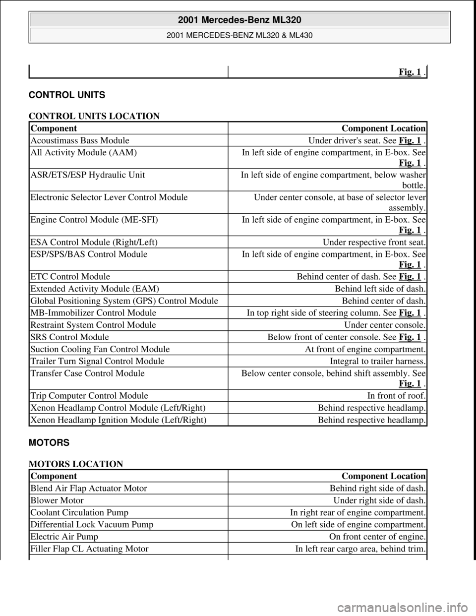
CONTROL UNITS
CONTROL UNITS LOCATION
MOTORS
MOTORS LOCATION
Fig. 1 .
ComponentComponent Location
Acoustimass Bass ModuleUnder driver's seat. See Fig. 1 .
All Activity Module (AAM)In left side of engine compartment, in E-box. See
Fig. 1
.
ASR/ETS/ESP Hydraulic UnitIn left side of engine compartment, below washer
bottle.
Electronic Selector Lever Control ModuleUnder center console, at base of selector lever
assembly.
Engine Control Module (ME-SFI)In left side of engine compartment, in E-box. See
Fig. 1
.
ESA Control Module (Right/Left)Under respective front seat.
ESP/SPS/BAS Control ModuleIn left side of engine compartment, in E-box. See
Fig. 1
.
ETC Control ModuleBehind center of dash. See Fig. 1 .
Extended Activity Module (EAM)Behind left side of dash.
Global Positioning System (GPS) Control ModuleBehind center of dash.
MB-Immobilizer Control ModuleIn top right side of steering column. See Fig. 1 .
Restraint System Control ModuleUnder center console.
SRS Control ModuleBelow front of center console. See Fig. 1 .
Suction Cooling Fan Control ModuleAt front of engine compartment.
Trailer Turn Signal Control ModuleIntegral to trailer harness.
Transfer Case Control ModuleBelow center console, behind shift assembly. See
Fig. 1
.
Trip Computer Control ModuleIn front of roof.
Xenon Headlamp Control Module (Left/Right)Behind respective headlamp.
Xenon Headlamp Ignition Module (Left/Right)Behind respective headlamp.
ComponentComponent Location
Blend Air Flap Actuator MotorBehind right side of dash.
Blower MotorUnder right side of dash.
Coolant Circulation PumpIn right rear of engine compartment.
Differential Lock Vacuum PumpOn left side of engine compartment.
Electric Air PumpOn front center of engine.
Filler Flap CL Actuating MotorIn left rear cargo area, behind trim.
2001 Mercedes-Benz ML320
2001 MERCEDES-BENZ ML320 & ML430
me
Saturday, October 02, 2010 3:21:17 PMPage 3 © 2006 Mitchell Repair Information Company, LLC.
Page 2144 of 4133
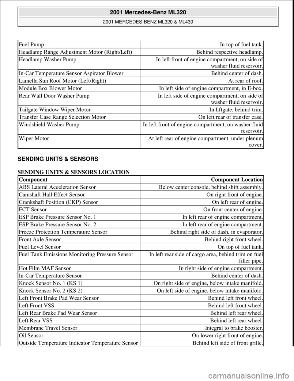
SENDING UNITS & SENSORS
SENDING UNITS & SENSORS LOCATION
Fuel PumpIn top of fuel tank.
Headlamp Range Adjustment Motor (Right/Left)Behind respective headlamp.
Headlamp Washer PumpIn left front of engine compartment, on side of
washer fluid reservoir.
In-Car Temperature Sensor Aspirator BlowerBehind center of dash.
Lamella Sun Roof Motor (Left/Right)At rear of roof.
Module Box Blower MotorIn left side of engine compartment, in E-box.
Rear Wall Door Washer PumpIn left side of engine compartment, on side of
washer fluid reservoir.
Tailgate Window Wiper MotorIn liftgate, behind trim.
Transfer Case Range Selection MotorOn left rear of transfer case.
Windshield Washer PumpIn left front of engine compartment, on washer fluid
reservoir.
Wiper MotorAt left rear of engine compartment, under plenum
cover.
ComponentComponent Location
ABS Lateral Acceleration SensorBelow center console, behind shift assembly.
Camshaft Hall Effect SensorOn right front of engine.
Crankshaft Position (CKP) SensorOn left rear of engine.
ECT SensorOn front center of engine.
ESP Brake Pressure Sensor No. 1In left rear of engine compartment.
ESP Brake Pressure Sensor No. 2In left rear of engine compartment.
Freeze Protection Temperature SensorBehind right side of dash, in evaporator.
Front Axle SensorBehind right front wheel.
Fuel Level SensorOn top of fuel tank.
Fuel Tank Emissions Monitoring Pressure SensorIn left rear side of cargo area, behind trim on fuel
filler pipe.
Hot Film MAF SensorIn right side of engine compartment.
In-Car Temperature SensorBehind center of dash.
Knock Sensor No. 1 (KS 1)On right side of engine, below intake manifold.
Knock Sensor No. 2 (KS 2)On left side of engine, below intake manifold.
Left Front Brake Pad Wear SensorBehind left front wheel.
Left Front VSSBehind left front wheel.
Left Rear Brake Pad Wear SensorBehind left rear wheel.
Left Rear VSSBehind left rear wheel.
Membrane Travel SensorIntegral to brake booster.
Oil SensorOn lower right front of engine.
Outside Temperature Indicator Temperature SensorBehind left side of front grille.
2001 Mercedes-Benz ML320
2001 MERCEDES-BENZ ML320 & ML430
me
Saturday, October 02, 2010 3:21:17 PMPage 4 © 2006 Mitchell Repair Information Company, LLC.