1997 MERCEDES-BENZ ML500 instrument cluster
[x] Cancel search: instrument clusterPage 2856 of 4133
Possible readouts are (text in parenthesis relates to models not fitted with multifunction display.):
"OIL LEVEL OKAY" ("o.k."),
1.0L, 1.5L, 2L,
"Overfilling" ("HI"),
"OBSERVE WAITING TIME" (clock symbol flashing and oil can symbol),
"DISPLAY OIL LEVEL" (clock and oil can symbols.)
If there is a fault at the oil sensor (oil level/temperature/quality, B40) the oil can symbol and the text "OIL
LEVEL SENSOR FAULTY" appears only 30 s after the fault has occurred.
(On models not fitted with multifunction display, the oil level warning lamp (A1e12) comes on accordingly.)
For diagnosis, read also the injection system control module (N3) with the HHT. (The instrument cluster (A1)
receives the sensor data through the CAN from the injection system control module (N3)).
Oil change
The ASSYST has to be reset each time the oil is changed. Resetting ASSYST also resets the remaining time and
the remaining distance. Resetting can be performed at the instrument cluster or using the HHT. The following
data are stored when the system is reset:
current kilometer reading rounded off to 100,
total oil replenishments in the last interval,
remaining distance,
remaining time,
product of the quality factors,
the data of the last 5 resettings in 5 data sets
These data can only be read with the HHT!
If the specified quantity of oil is not replenished when the oil is changed, the (internal) start distance is
reduced.
Detecting oil replenishments
With the HHT it is possible to retrieve the last 10 oil replenishments and the corresponding kilometer
readings of the current interval.
In the normal case, detection of an oil replenishment is displayed by the remaining distance in the
instrument cluster being extended
Oil replenishments are always only detected once the following conditions are met:
the replenished quantit
y is at least
2004 Mercedes-Benz ML350
1998-2005 GENINFO Overall vehicle - 163 Chassis
me
Saturday, October 02, 2010 3:47:47 PMPage 211 © 2006 Mitchell Repair Information Company, LLC.
Page 2857 of 4133
In the charts overleaf, a number of examples of this are presented. The horizontal (x) axis represents the service
interval and the vertical (y) axis is the remaining distance in each case in km.
conditions are met:
the replenished quantity is at least 1 l
after replenishing the oil, the car must be driven a distance of at least 5 km under normal driving
conditions at an oil temperature of at least 60°C
There are instances, however, in which the readout of the remaining distance nevertheless appears implausible
after replenishing oil; according to the display, no bonus or only a small bonus has been issued. This is caused
by the fact that the remaining distance is always only displayed within a range from 15 000 km up to 30 000 km
(or 20 000 km up to 40 000 km in the case of engine 668), but internally the system calculates with the actual
values which may also be beyond this range. These internal values can only be displayed with the HHT.
horizontal (x) axis represents the service interval and the vertical (y) axis is the remaining distance in each case
in km.
The readout of ASSYST in the instrument cluster always moves within the light range.
The remaining distance calculated internally may also, however, be within the two dark ranges. These internal
values can only be displayed with the HHT.
All examples relate to gasoline engines fitted with an oil sensor.
Example 1 :
Sufficient oil was added during the oil change. This means that the starting distance is 15 000 km.
After 10 000 km oil is topped up under normal driving conditions (a). The bonus (B1) is issued and displayed.
What this means is that when the remaining distance is retrieved, a greater remaining distance is displayed.
(Provided the aforementioned conditions for detecting the oil replenishment are met.)
Oil is topped up again after a further 5 000 km (b). In this case also a bonus (B2) is issued and displayed.
If, after this, no further oil is topped up and the car continues to be driven in the same manner, a service interval
of about 24 000 km is thus achieved.
In this example, the curve moves at all points within the light range of the chart; consequently, all the oil
replenishments are displayed by increasing the remaining distance.
2004 Mercedes-Benz ML350
1998-2005 GENINFO Overall vehicle - 163 Chassis
me
Saturday, October 02, 2010 3:47:47 PMPage 212 © 2006 Mitchell Repair Information Company, LLC.
Page 2860 of 4133
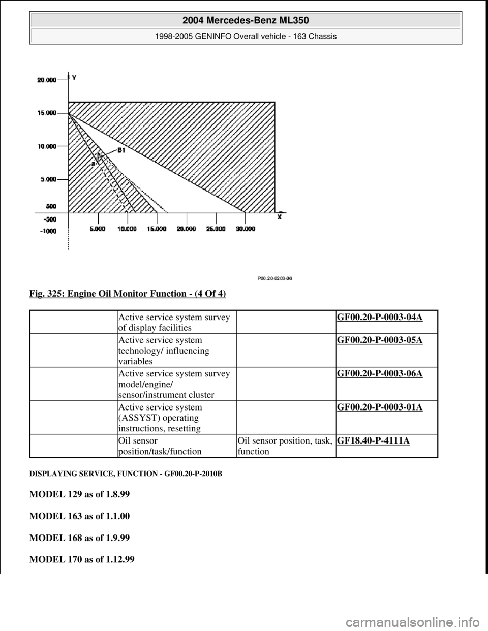
Fig. 325: Engine Oil Monitor Function - (4 Of 4)
DISPLAYING SERVICE, FUNCTION - GF00.20-P-2010B
MODEL 129 as of 1.8.99
MODEL 163 as of 1.1.00
MODEL 168 as of 1.9.99
MODEL 170 as of 1.12.99
Active service system survey
of display facilities GF00.20-P-0003-04A
Active service system
technology/ influencing
variables GF00.20-P-0003-05A
Active service system survey
model/engine/
sensor/instrument cluster GF00.20-P-0003-06A
Active service system
(ASSYST) operating
instructions, resetting GF00.20-P-0003-01A
Oil sensor
position/task/functionOil sensor position, task,
functionGF18.40-P-4111A
2004 Mercedes-Benz ML350
1998-2005 GENINFO Overall vehicle - 163 Chassis
me
Saturday, October 02, 2010 3:47:47 PMPage 215 © 2006 Mitchell Repair Information Company, LLC.
Page 2861 of 4133
MODEL 202 as of 1.8.99
Display of service to be performed
In addition to the various service displays, the service work to be performed (A or B) also appears.
The service symbol (wrench) appears once or twice in the display for this purpose.
The service symbol appears
once for service A
twice for service B .
A service A is always followed by a service B.
Following a service B, the next service must be calculated taking into account the kilometer readings. If the
distance of the current service interval is less than 22 000 km, the next service is service A, otherwise service B.
This calculation is now performed automatically in the instrument cluster (A1).
The path of the service displayed A or B can be processed in the service sheet without the need for a
calculation.
There is no external difference in the instrument clusters with and without the service display.
If service A (one service symbol) is displayed, it is then necessary to ensure by means of the production date
or the control unit identifier , that the vehicle in question is in fact a vehicle with service display . If this is
not the case, the service must be determined as specified in the service sheet.
The table below shows from which control unit identifier the instrument cluster features the service display:
The control unit identifier can be read with the HHT under menu point Control unit version.
SAFETY PRECAUTIONS
ModelControl unit identifier
1292/04
1633/04
1683/20
1702/23
2020/20
Displaying remaining
service function GF00.20-P-2007A
2004 Mercedes-Benz ML350
1998-2005 GENINFO Overall vehicle - 163 Chassis
me
Saturday, October 02, 2010 3:47:47 PMPage 216 © 2006 Mitchell Repair Information Company, LLC.
Page 3039 of 4133
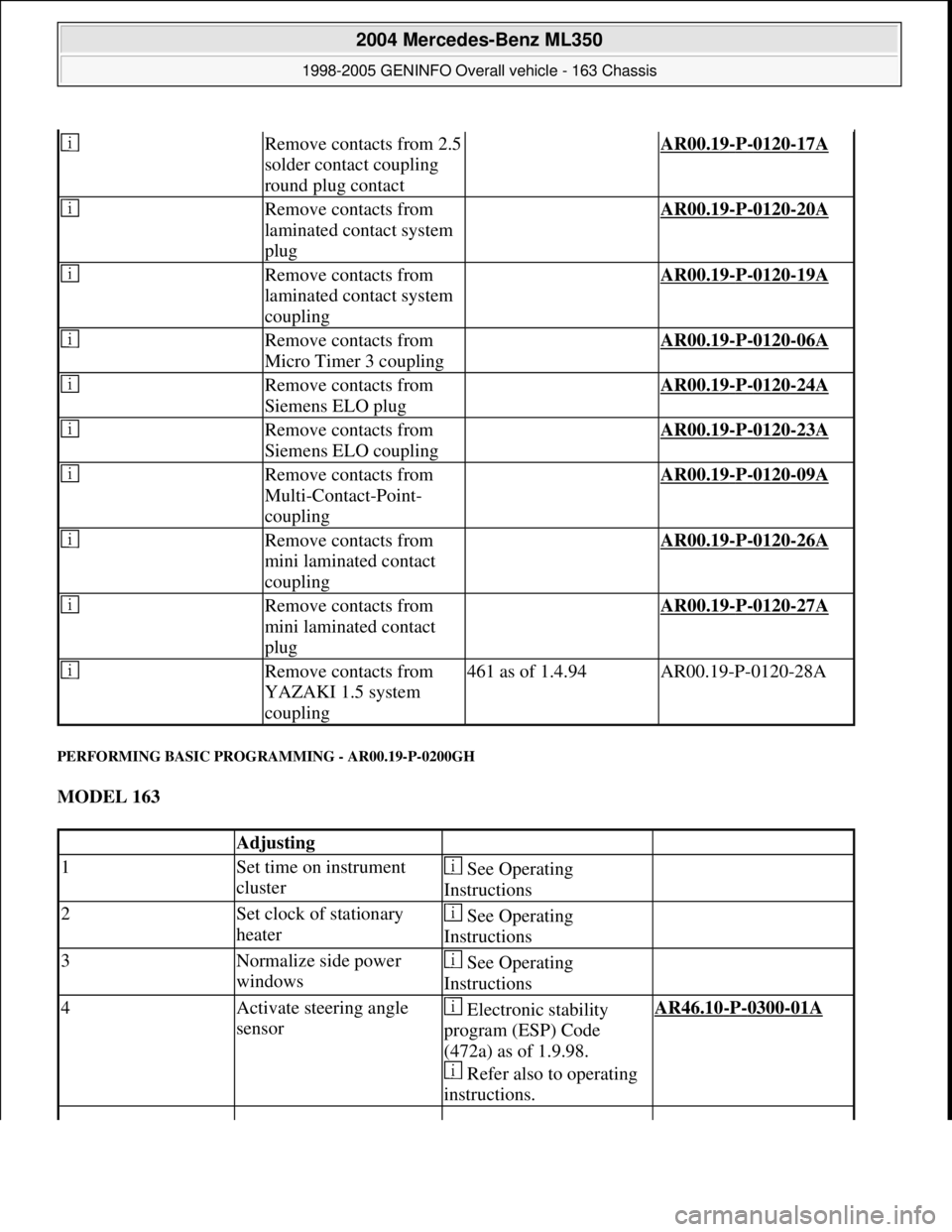
PERFORMING BASIC PROGRAMMING - AR00.19-P-0200GH
MODEL 163
Remove contacts from 2.5
solder contact coupling
round plug contact AR00.19-P-0120-17A
Remove contacts from
laminated contact system
plug AR00.19-P-0120-20A
Remove contacts from
laminated contact system
coupling AR00.19-P-0120-19A
Remove contacts from
Micro Timer 3 coupling AR00.19-P-0120-06A
Remove contacts from
Siemens ELO plug AR00.19-P-0120-24A
Remove contacts from
Siemens ELO coupling AR00.19-P-0120-23A
Remove contacts from
Multi-Contact-Point-
coupling AR00.19-P-0120-09A
Remove contacts from
mini laminated contact
coupling AR00.19-P-0120-26A
Remove contacts from
mini laminated contact
plug AR00.19-P-0120-27A
Remove contacts from
YAZAKI 1.5 system
coupling461 as of 1.4.94AR00.19-P-0120-28A
Adjusting
1Set time on instrument
cluster See Operating
Instructions
2Set clock of stationary
heater See Operating
Instructions
3Normalize side power
windows See Operating
Instructions
4Activate steering angle
sensor Electronic stability
program (ESP) Code
(472a) as of 1.9.98.
Refer also to operating
instructions.AR46.10-P-0300-01A
2004 Mercedes-Benz ML350
1998-2005 GENINFO Overall vehicle - 163 Chassis
me
Saturday, October 02, 2010 3:47:52 PMPage 394 © 2006 Mitchell Repair Information Company, LLC.
Page 3183 of 4133

GF54.30-P-2017A
HHT interface, location/task
7.7.99
MODEL
129, 140 as of 1.6.96,
163, 168, 170,
202 as of 1.8.96,
208 up to 31.7.99,
210 as of 1.6.96 up to 30.6.99
The instrument cluster has diagnostic capabilities. In other words,
diagnosis is possible using a hand held test (HHT). The instrument
cluster therefore has a line (K-line) which is connected to the data
link connector (X11/4).
The instrument cluster, including the Active Service System
(ASSYST), is tested with the HHT. The following functions can be
selected:
D
Control module version
D
Error memory
D
Actual valves
D
Controls
D
Manual transmission adaptation:
- variant coding
- settings
Copyright DaimlerChrysler AG 05.06.2006 CD-Ausgabe G/10/04 . This WIS print-out will not be recorde
d by Modification services.
Page 1
Page 3185 of 4133

AD54.30-P-2000-02GC
Notes on HHT previous knowledge diagnosis
IC
HHT :
The instrument cluster and active service system (ASSYST) sub-
function are checked with HHT, there being the choice of the
following functions for this:
1. Control module version
2. Fault memory
3. Actual values
4. Actuations
5. Control module adaptation
Additional information on test items 2, 3 and 5 can be called up using
the INPUT key
Control module adaptation
The following alternatives are available in the HHT under control
module adaptation:
1.)
Read out coding and transfer to new instrument cluster. IC and
ASSYST.
2.)
Read out/change codings e.g.:
Engine and national variants,
version of fuel tank,
special equipment etc.
3.)
Settings:
1
Clock
2
Put forward kilometer reading
3
Put back kilometer reading
4
Oil change
5
Reset oil change initiated inadvertently
6
Active Service System
7
Enter times with battery disconnected
8
Set minimum oil warning
Before replacing a defective instrument cluster, readout the existing
variant codings (driving data and instrument cluster data) and store in
the HHT on an interim basis. Read in the values stored on an interim
basis again after installing the new instrument cluster.
If it is not possible to read out the stored variant coding, all variant
codings must be input manually (menu-assistance in HHT).
When installing an instrument cluster on an experimental basis, do
not put forward the kilometer reading as it cannot be put back later.
Copyright DaimlerChrysler AG 05.06.2006 CD-Ausgabe G/10/04 . This WIS print-out will not be recorde
d by Modification services.
Page 1
Page 3216 of 4133
Fig. 2: Locating Climate Control Components
Courtesy of MERCEDES-BENZ OF NORTH AMERICA
FRESH/RECIRCULATION SWITCH
Fresh/recirculation switch controls voltage signal to fresh air recirculation door motor. See Fig. 1 and Fig. 2 .
With switch indicator light on, air will recirculate. With switch indicator light off, air will enter from outside of
vehicle.
A/C CONTROL MODULE
The A/C control module (A/C amplifier) is the control unit for the A/C system. See Fig. 2 . The module
receives inputs from various sensors and processes the information to control various outputs for the A/C
system for optimal control.
The A/C control module inputs are as follows:
A/C Switch
In-Vehicle Air Temperature Sensor
Temperature Selector Knob
Blower Motor Knob
Evaporator Temperature Sensor
Air Mix Damper Door Position Sensor
The A/C control module output functions are as follows:
Air Mix Damper Door Motor
All Activity Module
Fresh/Recirculation Door Motor
ALL ACTIVITY MODULE
All Activity Module (AAM) receives inputs to determine if specified conditions have been met to allow
operation of A/C-heater system. If conditions are met, the AAM will send signals to the A/C compressor,
condenser fans relay and the blower motor relay to command or enable operation.
IN-VEHICLE TEMPERATURE SENSOR
The in-vehicle temperature sensor is a negative temperature coefficient resistor. Sensor sends signals to the A/C
control module to maintain in-vehicle temperature. Sensor is located on the center panel of the instrument
cluster.
DUST FILTER
A dust filter provides filtering of air entering or recirculating in the passenger's compartment. The dust filter is
mounted between blower motor and evaporator, below passen
ger's side of instrument panel, to left of blower
2001 Mercedes-Benz ML320
2000-01 MANUAL A/C-HEATER SYSTEMS ML 320, ML 430 & ML 55
me
Saturday, October 02, 2010 3:25:10 PMPage 5 © 2006 Mitchell Repair Information Company, LLC.