1997 MERCEDES-BENZ ML500 instrument cluster
[x] Cancel search: instrument clusterPage 3232 of 4133
Fig. 6: Removing Cooling Fans & Condenser
Courtesy of MERCEDES-BENZ OF NORTH AMERICA.
COOLING FANS
Removal & Installation
Remove headlight units. Remove upper frame crossmember, release hood release control cable and remove
crossmember. See Fig. 6
. Remove 2 cooling fans frame bolts on radiator. Disconnect cooling fan connector.
Release outside temperature sensor wiring harness. Pull up on cooling fan and remove. To install, reverse
removal procedure. Ensure cooling fan bottom guides are properly seated in lower mounts.
EVAPORATOR
Removal & Installation
Remove A/C housing unit. See A/C HOUSING UNIT . Remove expansion valve. See Fig. 5 . Discard "O"
rings. Disassemble A/C housing unit. Remove evaporator. Remove evaporator temperature sensor. To install,
reverse removal procedure. Use NEW "O" rings lubricated with refrigerant oil. If installing a new or repair
evaporator, add 1.35 ounces of NEW refrigerant oil to evaporator.
EXPANSION VALVE
Removal & Installation
1. Discharge A/C system, using approved refrigerant recovery/recycling equipment. Without disconnecting
coolant hoses, remove coolant expansion reservoir and set aside. Remove refrigerant line bracket and
loosen clamps. See Fig. 5
. Pull refrigerant lines out of expansion valve.
2. Remove expansion valve self-locking nut and discard. Remove expansion valve. Discard "O" rings. To
install, reverse removal procedure. Use NEW "O" rings lubricated with refrigerant oil. Tighten NEW self-
locking nut to specification. See TORQUE SPECIFICATIONS
.
INSTRUMENT PANEL & INSTRUMENT PANEL CARRIER
Removal & Installation
1. Secure vehicle against rolling. Set transmission selector to "D" position. Obtain radio security code.
Disconnect negative battery cable. Remove driver-side air bag.
2. Place match marks on steering wheel and steering shaft. Remove steering wheel, upper steering column
covers and combination switch. Remove instrument cluster cover frame. Remove one instrument panel
lower section bolt.
3. Remove screws in footwell from left side of instrument panel bottom section. Remove instrument panel
center section. Remove 4 A/C control panel screws and remove control panel. See Fig. 1
. Release pull
cables and disconnect connectors.
4. Remove screws from center section. Remove glove box. Remove screws in footwell from right side of
instrument panel bottom section. Remove entry courtesy lights. Remove end covers and screws.
5. Release 4 "A" clips between instrument panel bottom section and upper section. See Fig. 7
. Release
parkin
g brake release cable from handle. With assistance, remove instrument panel bottom section.
2001 Mercedes-Benz ML320
2000-01 MANUAL A/C-HEATER SYSTEMS ML 320, ML 430 & ML 55
me
Saturday, October 02, 2010 3:25:10 PMPage 21 © 2006 Mitchell Repair Information Company, LLC.
Page 3233 of 4133
6. Remove A-pillar panel trim. Remove instrument cluster. Remove defroster vent cover. Remove air vents
and side air nozzles. With assistance, remove upper instrument panel.
7. Remove passenger-side air bag. Remove right side lower instrument panel cover. Remove instrument
panel carrier screws from A/C housing unit. Remove left side lower instrument panel cover.
8. Remove insulating mat between steering column and instrument panel carrier. Remove steering column
bolts and nuts from instrument panel carrier. See Fig. 8
. Remove instrument panel carrier center tunnel
bolts. Disconnect steering column connectors.
9. Remove wiring harness from instrument panel carrier. Remove wiper washer system. Remove instrument
panel carrier nuts from engine compartment side of firewall.
10. Remove A-pillar bolt covers and remove instrument panel carrier A-pillar bolts. With assistance, remove
instrument panel carrier through passenger door. To install, reverse removal procedure.
11. Ensure instrument panel bottom section guide tongues "B" are seated into instrument panel upper section
mounts. See Fig. 8
. Tighten nuts and bolts to specification. See TORQUE SPECIFICATIONS .
Recode radio. See RECODING RADIO
under PROGRAMMING.
Fig. 7: Removing Instrument Panel Bottom Section
Courtesy of MERCEDES-BENZ OF NORTH AMERICA.
2001 Mercedes-Benz ML320
2000-01 MANUAL A/C-HEATER SYSTEMS ML 320, ML 430 & ML 55
me
Saturday, October 02, 2010 3:25:10 PMPage 22 © 2006 Mitchell Repair Information Company, LLC.
Page 3343 of 4133
This input information is relayed by the CDI control module (N3/9) to the integrated control module of the
electric engine/AC intake fan with integrated control (M4/7).
Engines 113.942 and 113.981
The all-activity module (AAM) (N10) receives the coolant temperature via the coolant temperature sensor and
the refrigerant pressure via the refrigerant pressure sensor (B12).
This input information is relayed by the all-activity module (AAM) (N10) to the integrated control module of
the engine and AC electric suction fan with integrated control (M4/7)
There the input information is compared with the stored values and, if necessary, the speed of the engine and
AC electric suction fan with integrated control (M4/7) is increased to 100 %.
The engine and AC electric suction fan with integrated control (M4/7) operates with AC switched on and in the
reheat mode for basic ventilation with a capacity of up to 20 %.
The basic ventilation can be switched off under the following conditions:
At an outdoor temperature of < or = 15°C the value of the outdoor temperature is transmitted from the
outside temperature sensor (B10/5) to the AC control module (N19).
The pressure-dependent fan speed remains the same.
At a vehicle speed of > 75 km/h
The vehicle speed value comes from the traction system control module via the instrument cluster (A1)
and CDI control module (N3/9), to the control module integrated in the electric suction fan engine and
AC with integrated control (M4/7). The pressure-dependent fan speed remains the same.
An overrun time of 60 s can be set in order to ensure that the engine and AC electric suction fan with integrated
control (M4/7) will continue to operate even where the refrigerant compressor is temporarily switched off by
the icing protection.
The engine and AC electric suction fan with integrated control (M4/7) has a power rating of 550W.
ELECTRIC FAN, ENGINE/AIR CONDITIONING, LOCATION - GF83.40-P-2118-02GH
The engine and AC electric suction fan with integrated control (M4/7) is located immediately in front of the
condenser.
2001 Mercedes-Benz ML320
1998-2005 HVAC Climate Control - 163 Chassis
me
Saturday, October 02, 2010 3:23:16 PMPage 99 © 2006 Mitchell Repair Information Company, LLC.
Page 3385 of 4133
The in-car temperature sensor (B10/4) is equipped with an aspirator blower which constantly draws air out of
the vehicle interior for the temperature measurement when the ignition is ON . The in-car temperature sensor
(B10/4) records the interior temperature and conveys it to the AAC push-button control module. A comparison
is made there with the setting on the temperature selector and the blend air flap is repositioned depending on the
result of this comparison.
It is connected to the AAC push-button control module via a separate electric cable.
Constant circulation of the interior air at the in-car temperature sensor (B10/4) is achieved by the in-car
temperature sensor aspirator blower (M9) and therefore ensures a high level of control accuracy.
In contrast to the previous suction jet nozzle a high level of control accuracy is ensured by the in-car
temperature sensor aspirator blower (M9).
OUTSIDE AIR TEMPERATURE SENSOR FUNCTION - GF83.57-P-2103-01GH
Function
The resistance of the outside air temperature sensor (B10/5) depends on the ambient temperature and the ground
speed. With an increase in the outside temperature, its resistance decreases. This information is sent to the air
conditioning control module (N19). This information causes a slight lowering or raising of the temperature
selected at the air conditioning control panel.
This achieves an adaptation to the temperature perception of the occupants.
The outside temperature depends on the ground speed, which prevents a value for the outside temperature that is
too high - as may occur when the vehicle is stationary or when traveling slowly, e.g. due to thermal radiation
from the engine - from being sent to the air conditioning control module (N19).
The value of the ground speed is sent from the traction systems control module (N47) via the instrument cluster
(A1) to the air conditioning control module (N19).
When switching the ignition off and on and with speeds lower than 20 km/h the temperature measured last is
used.
OUTSIDE AIR TEMPERATURE SENSOR POSITION - GF83.57-P-2103-02GH
The outside air temperature sensor (B10/5) is located at the front on the air inlet of the evaporator housing.
2001 Mercedes-Benz ML320
1998-2005 HVAC Climate Control - 163 Chassis
me
Saturday, October 02, 2010 3:23:17 PMPage 141 © 2006 Mitchell Repair Information Company, LLC.
Page 3389 of 4133
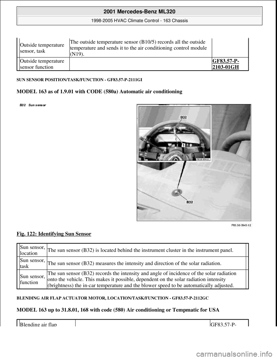
SUN SENSOR POSITION/TASK/FUNCTION - GF83.57-P-2111GI
MODEL 163 as of 1.9.01 with CODE (580a) Automatic air conditioning
Fig. 122: Identifying Sun Sensor
BLENDING AIR FLAP ACTUATOR MOTOR, LOCATION/TASK/FUNCTION - GF83.57-P-2112GC
MODEL 163 up to 31.8.01, 168 with code (580) Air conditioning or Tempmatic for USA
Outside temperature
sensor, taskThe outside temperature sensor (B10/5) records all the outside
temperature and sends it to the air conditioning control module
(N19).
Outside temperature
sensor function GF83.57-P-
2103-01GH
Sun sensor,
locationThe sun sensor (B32) is located behind the instrument cluster in the instrument panel.
Sun sensor,
taskThe sun sensor (B32) measures the intensity and direction of the solar radiation.
Sun sensor,
functionThe sun sensor (B32) records the intensity and angle of incidence of the solar radiation
onto the vehicle. This makes it possible, dependent on the solar radiation intensity
(brightness) the in-car temperature and the blower speed to be automatically adjusted.
Blending air flap GF83.57-P-
2001 Mercedes-Benz ML320
1998-2005 HVAC Climate Control - 163 Chassis
me
Saturday, October 02, 2010 3:23:17 PMPage 145 © 2006 Mitchell Repair Information Company, LLC.
Page 3422 of 4133
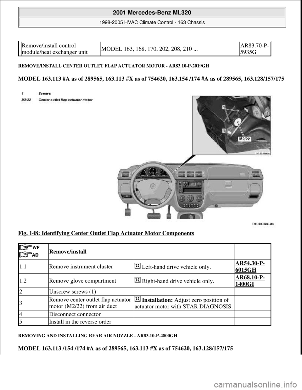
REMOVE/INSTALL CENTER OUTLET FLAP ACTUATOR MOTOR - AR83.10-P-2019GH
MODEL 163.113 #A as of 289565, 163.113 #X as of 754620, 163.154 /174 #A as of 289565, 163.128/157/175
Fig. 148: Identifying Center Outlet Flap Actuator Motor Components
REMOVING AND INSTALLING REAR AIR NOZZLE - AR83.10-P-4800GH
MODEL 163.113 /154 /174 #A as of 289565, 163.113 #X as of 754620, 163.128/157/175
Remove/install control
module/heat exchanger unitMODEL 163, 168, 170, 202, 208, 210 ...AR83.70-P-
5935G
Remove/install
1.1Remove instrument cluster Left-hand drive vehicle only.AR54.30-P-
6015GH
1.2Remove glove compartment Right-hand drive vehicle only.AR68.10-P-
1400GI
2Unscrew screws (1)
3Remove center outlet flap actuator
motor (M2/22) from air duct Installation: Adjust zero position of
actuator motor with STAR DIAGNOSIS.
4Disconnect connector
5Install in the reverse order
2001 Mercedes-Benz ML320
1998-2005 HVAC Climate Control - 163 Chassis
me
Saturday, October 02, 2010 3:23:18 PMPage 178 © 2006 Mitchell Repair Information Company, LLC.
Page 3466 of 4133
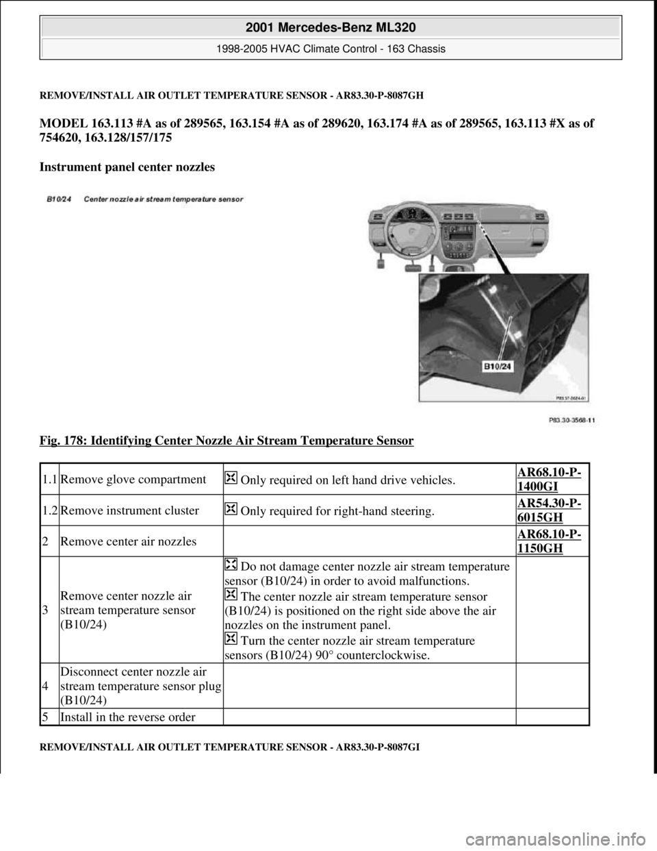
REMOVE/INSTALL AIR OUTLET TEMPERATURE SENSOR - AR83.30-P-8087GH
MODEL 163.113 #A as of 289565, 163.154 #A as of 289620, 163.174 #A as of 289565, 163.113 #X as of
754620, 163.128/157/175
Instrument panel center nozzles
Fig. 178: Identifying Center Nozzle Air Stream Temperature Sensor
REMOVE/INSTALL AIR OUTLET TEMPERATURE SENSOR - AR83.30-P-8087GI
1.1Remove glove compartment Only required on left hand drive vehicles.AR68.10-P-
1400GI
1.2Remove instrument cluster Only required for right-hand steering.AR54.30-P-
6015GH
2Remove center air nozzles AR68.10-P-
1150GH
3
Remove center nozzle air
stream temperature sensor
(B10/24)
Do not damage center nozzle air stream temperature
sensor (B10/24) in order to avoid malfunctions.
The center nozzle air stream temperature sensor
(B10/24) is positioned on the right side above the air
nozzles on the instrument panel.
Turn the center nozzle air stream temperature
sensors (B10/24) 90° counterclockwise.
4
Disconnect center nozzle air
stream temperature sensor plug
(B10/24)
5Install in the reverse order
2001 Mercedes-Benz ML320
1998-2005 HVAC Climate Control - 163 Chassis
me
Saturday, October 02, 2010 3:23:19 PMPage 222 © 2006 Mitchell Repair Information Company, LLC.
Page 3483 of 4133

GF54.30-P-3002A
Indicator and warning signals triggered over direct lines, function
24.10.96
MODEL
129, 140 as of 1.6.96,
163, 168, 170,
202 as of 1.8.96,
208 up to 31.7.99,
210 as of 1.6.96 up to 30.6.99
Indicator and warning signals
Indicator lamps for left turn signal (A1e1) and right turn signal
(A1e2)
The signal in models 129, 140, 170, 202 comes from the
combination relay (turn signals with trailer coupling, rear
window defroster, wiper motor, anti-theft alarm system)
(N10/2), and in model 210 from the multifunction control
module (N10-1) or the driver's side signal acquisition and
actuation module (SAM) (N10/1).
In model 168 the entire turn signal control is located in the
instrument cluster (A1).
Brake fluid / parking brake warning lamp (A1e7)
The signal for the brake fluid comes direct from the brake fluid level switch (S11) (except model 163).
(The signal for the parking brake comes over CAN.)
Low windshield washer fluid level warning lamp (A1e13) except
models 163 and 168
See
document: Coolant/washer fluid level voltage coding, task /
function
-----------------------------------------------------------------------------------------
Low windshield washer fluid level warning lamp (A1e13) as of
01.09.01 for model 163
See document: Displaying washer fluid level, function
Low engine coolant level warning lamp (A1e11) except models
163 and 168
See
document: Coolant/washer fluid level voltage coding, task /
function
Low engine coolant level warning lamp (A1e11) model 163 as of
3.99
See
document: Displaying coolant level, function
Coolant level and temperature warning lamp (A1e11) model 168
as of 9.99
See
document: Displaying coolant level, function
Fuel reserve warning lamp (A1e4)
When the reserve fuel level is reached, this lamp lights up and
goes out again only after refueling is detected. If the vehicle is
refueled with the ignition ON, refueling is detected only if at
least 7 liters of fuel are added.
-----------------------------------------------------------------------------------------
AIRBAG OFF indicator lamp (A1e56), only model 163 except
I
The signal comes from the emergency tensioning retractor
(ETR) control module with airbag (AB, N2/2)
Generator charge indicator/warning lamp (A1e5)
See document: Terminal 61 and terminal 61e, charge indicator
lamp, exterior lamp failure, function
Seatbelt/backrest lock warning lamp (A1e9)
The seat belt warning lamp is only used in a few national
versions, and is actuated direct by a seat belt buckle switch
(normally closed contact). After engine start, the lamp flashes
for a short time (approx. 6 seconds).
In model 129 if this lamp fails to go out after flashing briefly, but
continues to shine constantly, then the seat backrest is not
locked.
Exterior lamp failure indicator lamp (A1e14)
The signal comes from the lamp failure monitor
See document: Terminal 61 and terminal 61e, charge indicator
lamp, exterior lamp failure, function
Hydraulic fluid level warning lamp (A1e37)
The signal comes direct from the ADS level control oil level
switch (S44).
ADS warning lamp, suspension (A1e27) The signal comes from the ADS control module, suspension
(N51).
SRS airbag malfunction indicator lamp (A1e15)
The signal comes from the emergency tensioning retractor
(ETR) control module with airbag (AB, N2/2)
Voltage coding of coolant / windshield washer
fluid level, function
Except models 163 and 168
GF54.30-P-3006A
Displaying coolant level, function
Model 163 as of 3.99
GF54.30-P-3028GH
Model 168 as of 9.99
GF54.30-P-3028GC
Terminal 61 and terminal 61e, charge
indicator lamp, exterior lamp failure, function
GF54.30-P-3007A
Copyright DaimlerChrysler AG 04.06.2006 CD-Ausgabe G/10/04 . This WIS print-out will not be recorde
d by Modification services.
Page 1