1997 MERCEDES-BENZ ML500 instrument cluster
[x] Cancel search: instrument clusterPage 3499 of 4133
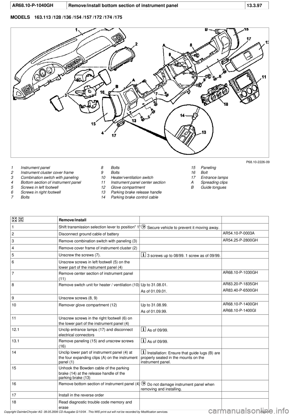
AR68.10-P-1040GH
Remove/install bottom section of instrument panel
13.3.97
MODELS
163.113 /128 /136 /154 /157 /172 /174 /175
P68.10-2226-09
1
Instrument panel
2
Instrument cluster cover frame
3
Combination switch with paneling
4
Bottom section of instrument panel
5
Screws in left footwell
6
Screws in right footwell
7
Bolts
15
Paneling
16
Bolt
17
Entrance lamps
A
Spreading clips
B
Guide tongues
8
Bolts
9
Bolts
10
Heater/ventilation switch
11
Instrument panel center section
12
Glove compartment
13
Parking brake release handle
14
Parking brake control cable
Remove/install
1
Shift transmission selection lever to position" 1"
Secure vehicle to prevent it moving away.
2
Disconnect ground cable of battery
AR54.10-P-0003A
3
Remove combination switch with paneling (3)
AR54.25-P-2800GH
4
Remove cover frame of instrument cluster (2)
5
Unscrew the screws (7).
3 screws up to 08/99. 1 screw as of 09/99.
6
Unscrew screws in left footwell (5) on the
lower part of the instrument panel (4)
7
Remove center section of instrument panel
(11)
AR68.10-P-1030GH
8
Remove switch unit for heater / ventilation (10)
Up to 31.08.01.
AR83.20-P-1835GH
As of 01.09.01.
AR83.40-P-6500GH
9
Unscrew screws (8, 9)
10
Remover glove compartment (12)
Up to 31.08.99.
AR68.10-P-1400GH
As of 01.09.99.
AR68.10-P-1400GI
11
Unscrew screws in the right footwell (6) on
the lower part of the instrument panel (4)
12.1
Unclip entrance lamps (17) and disconnect
electrical connectors
As of 09/99.
13.1
Remove paneling (15) and unscrew screws
(16)
As of 09/99.
14
Unclip lower part of instrument panel (4) at
the four expanding clips (A) on the instrument
panel (1)
Installation: Ensure that guide lugs (B) are
properly seated in the mounts on the
instrument panel.
15
Unhook the Bowden cable of the parking
brake (14) at the release handle of the
parking brake (13)
16
Remove bottom section of instrument panel (4)
Do not damage instrument panel when
removing and installing.
17
Install in the reverse order
18
Read diagnostic trouble code memory and
erase
Copyright DaimlerChrysler AG 09.05.2006 CD-Ausgabe G/10/04 . This WIS print-out will not be recorde
d by Modification services.
Page 1
Page 3515 of 4133
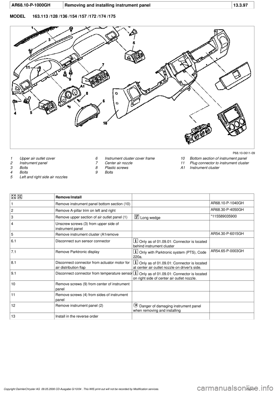
AR68.10-P-1000GH
Removing and installing instrument panel
13.3.97
MODEL
163.113 /128 /136 /154 /157 /172 /174 /175
P68.10-0611-09
1
Upper air outlet cover
2
Instrument panel
3
Bolts
4
Bolts
5
Left and right side air nozzles
10
Bottom section of instrument panel
11
Plug connector to instrument cluster
A1
Instrument cluster
6
Instrument cluster cover frame
7
Center air nozzle
8
Plastic screws
9
Bolts
Remove/install
1
Remove instrument panel bottom section (10)
AR68.10-P-1040GH
2
Remove A-pillar trim on left and right
AR68.30-P-4050GH
3
Remove upper section of air outlet panel (1)
Long wedge
*115589035900
4
Unscrew screws (3) from upper side of
instrument panel
5
Remove instrument cluster (A1remove
AR54.30-P-6015GH
6.1
Disconnect sun sensor connector
Only as of 01.09.01: Connector is located
behind instrument cluster
7.1
Remove Parktronic display
Only with Parktronic system (PTS), Code
220a.
AR54.65-P-0003GH
8.1
Disconnect connector from actuator motor for
air distribution flap
Only as of 01.09.01: Connector is located
at center air outlet nozzle on driver's side.
9.1
Disconnect connector from temperature sensor
Only as of 01.09.01: Connector is located
on right side of center air outlet nozzle.
10
Remove screws (9) from center of instrument
panel
11
Remove screws (4) from sides of instrument
panel
12
Remove instrument panel (2)
Danger of damaging instrument panel
when removing and installing
13
Install in the reverse order
Copyright DaimlerChrysler AG 09.05.2006 CD-Ausgabe G/10/04 . This WIS print-out will not be recorde
d by Modification services.
Page 1
Page 3534 of 4133
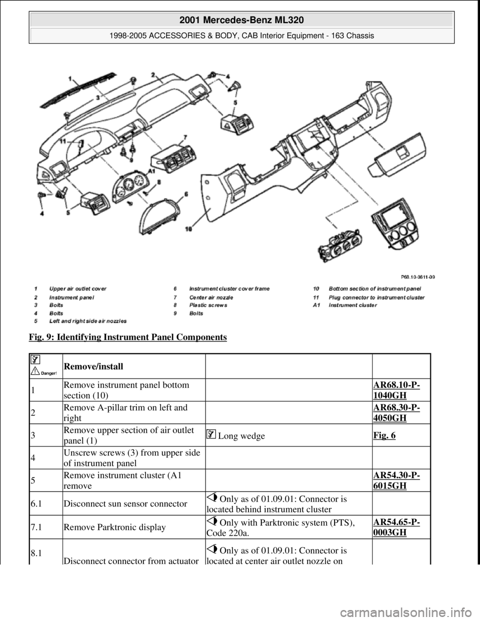
Fig. 9: Identifying Instrument Panel Components
Remove/install
1Remove instrument panel bottom
section (10) AR68.10-P-
1040GH
2Remove A-pillar trim on left and
right AR68.30-P-
4050GH
3Remove upper section of air outlet
panel (1) Long wedgeFig. 6
4Unscrew screws (3) from upper side
of instrument panel
5Remove instrument cluster (A1
remove AR54.30-P-
6015GH
6.1Disconnect sun sensor connector Only as of 01.09.01: Connector is
located behind instrument cluster
7.1Remove Parktronic display Only with Parktronic system (PTS),
Code 220a.AR54.65-P-
0003GH
8.1
Disconnect connector from actuator
Only as of 01.09.01: Connector is
located at center air outlet nozzle on
2001 Mercedes-Benz ML320
1998-2005 ACCESSORIES & BODY, CAB Interior Equipment - 163 Chassis
me
Saturday, October 02, 2010 3:35:21 PMPage 16 © 2006 Mitchell Repair Information Company, LLC.
Page 3538 of 4133
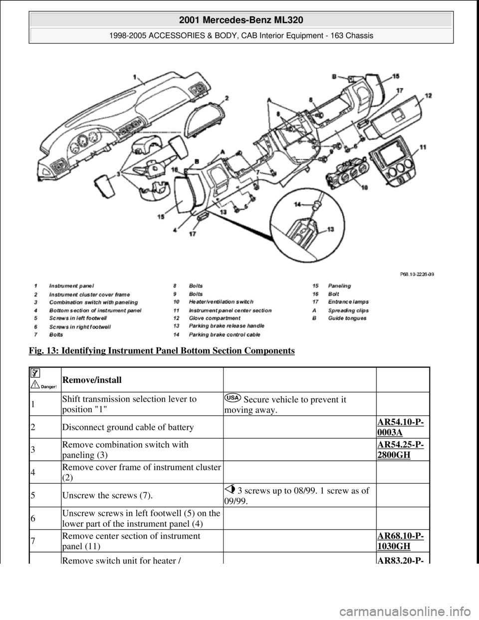
Fig. 13: Identifying Instrument Panel Bottom Section Components
Remove/install
1Shift transmission selection lever to
position "1" Secure vehicle to prevent it
moving away.
2Disconnect ground cable of battery AR54.10-P-
0003A
3Remove combination switch with
paneling (3) AR54.25-P-
2800GH
4Remove cover frame of instrument cluster
(2)
5Unscrew the screws (7). 3 screws up to 08/99. 1 screw as of
09/99.
6Unscrew screws in left footwell (5) on the
lower part of the instrument panel (4)
7Remove center section of instrument
panel (11) AR68.10-P-
1030GH
Remove switch unit for heater / AR83.20-P-
2001 Mercedes-Benz ML320
1998-2005 ACCESSORIES & BODY, CAB Interior Equipment - 163 Chassis
me
Saturday, October 02, 2010 3:35:21 PMPage 20 © 2006 Mitchell Repair Information Company, LLC.
Page 3553 of 4133
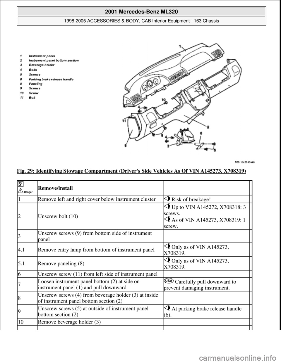
Fig. 29: Identifying Stowage Compartment (Driver's Side Vehicles As Of VIN A145273, X708319)
Remove/install
1Remove left and right cover below instrument cluster Risk of breakage!
2Unscrew bolt (10)
Up to VIN A145272, X708318: 3
screws.
As of VIN A145273, X708319: 1
screw.
3Unscrew screws (9) from bottom side of instrument
panel
4.1Remove entry lamp from bottom of instrument panel Only as of VIN A145273,
X708319.
5.1Remove paneling (8) Only as of VIN A145273,
X708319.
6Unscrew screw (11) from left side of instrument panel
7Loosen instrument panel bottom (2) at side on
instrument panel (1) and pull downward Carefully pull downward to
prevent damaging instrument.
8Unscrew screws (4) from beverage holder (3) at inside
of instrument panel bottom section (2)
9Unscrew screws (5) at outside of instrument panel
bottom section (2) At parking brake release handle
(6).
10Remove beverage holder (3)
2001 Mercedes-Benz ML320
1998-2005 ACCESSORIES & BODY, CAB Interior Equipment - 163 Chassis
me
Saturday, October 02, 2010 3:35:21 PMPage 35 © 2006 Mitchell Repair Information Company, LLC.
Page 3594 of 4133
MODEL all
CLEAN INSTRUMENT CLUSTER, STEERING WHEEL AND GEARSHIFT LEVER (STANDARD VERSION) - AP68.10-P-
1000-01A
all
Work procedure
Wipe off with moist, lent-free rag.
Do not use scouring agent to prevent scratching surfaces.
Do not bring Plexiglas cover on instrument cluster and Mercedes Star in steering wheel into contact with
solvent or cleaning agents containing solvents (danger of tension cracking).
Do not apply liquids to Plexiglas cover on instrument cluster.
Repair materials
Cleaning vehicle headliners of textile material (prefabricated headliners), floor
coverings, rear shelf coverings, and other textiles AP68.00-P-
1000-01A
Cleaning synthetic leather vehicle headliners (tensioned headliners) AP68.00-P-
1000-02A
Cleaning seat belts AP91.40-P-
1000-01A
Cleaning instrument cluster, steering wheel and gearshift lever (standard version) AP68.10-P-
1000-01A
Cleaning leather upholstery, leather steering wheel, and leather gearshift lever AP91.18-P-
1000-01A
Cleaning plastic covering parts AP68.30-P-
1000-01A
Cleaning MB Tex upholstery AP91.18-P-
1000-02A
Cleaning fabric upholstery AP91.18-P-
1000-03A
Cleaning velours upholstery AP91.18-P-
1000-04A
Cleaning amaretta upholstery AP91.18-P-
1000-05A
NumberDesignationOrder number
BR00.45-Z-1002-04ACar shampooA 001 986 41 71
2001 Mercedes-Benz ML320
1998-2005 ACCESSORIES & BODY, CAB Interior Equipment - 163 Chassis
me
Saturday, October 02, 2010 3:35:22 PMPage 76 © 2006 Mitchell Repair Information Company, LLC.
Page 3715 of 4133

AD00.00-P-2000-02C
Assignment of data link connector
P07.00-0323-10
X11/22
Data link connector
1
Electronic ignition/starter switch control module (model
168)
2 -
3
TNA signal (gasoline)
3
TD signal (diesel)
4
Circuit 31 (ground)
5
Circuit 31 (electronics ground)
6
CAN interior bus (H)
7
ME
Motor electronics (ME-SFI)
8
Circuit 87 voltage
9
ABS
Anti-lock brake system (model 168)
9
ETS
Electronic traction system (model 163)
9
ASR
Acceleration slip regulation (model 168)
9
ESP
Electronic Stability Program
10
-
11 ETC
Electronic transmission control
11
FTC
Front transmission control (model 168)
11
Automatic clutch (model 168)
12
AAM
All activity module
12
RD
Radio Audio 10, Audio 30, and Audio 30 APS with D2B
(model 168)
13
AB
Airbag/emergency tensioning retractor
14
CAN interior bus (L)
15 IC
Instrument cluster
16
Circuit 30 voltage 30
Copyright DaimlerChrysler AG 05.06.2006 CD-Ausgabe G/10/04 . This WIS print-out will not be recorde
d by Modification services.
Page 1
Page 3723 of 4133
GF18.40-P-4111-02A
Oil sensor function
n
P18.40-2046-12
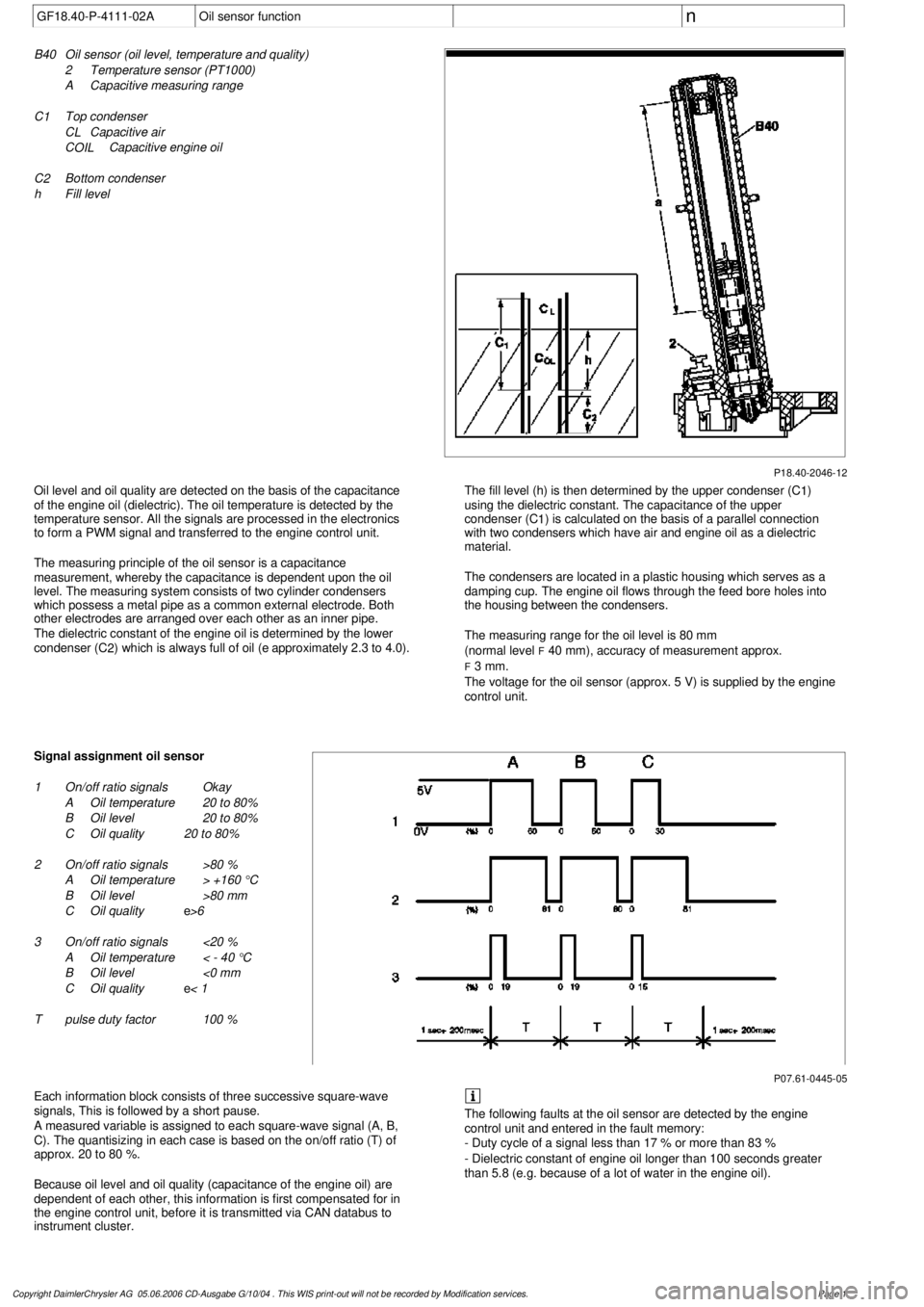
B40
Oil sensor (oil level, temperature and quality)
2
Temperature sensor (PT1000)
A
Capacitive measuring range
C 1
Top condenser
C L
Capacitive air
C
OIL
Capacitive engine oil
C 2
Bottom condenser
h
Fill level
Oil level and oil quality are detected on the basis of the capacitance
of the engine oil (dielectric). The oil temperature is detected by the
temperature sensor. All the signals are processed in the electronics
to form a PWM signal and transferred to the engine control unit.
The measuring principle of the oil sensor is a capacitance
measurement, whereby the capacitance is dependent upon the oil
level. The measuring system consists of two cylinder condensers
which possess a metal pipe as a common external electrode. Both
other electrodes are arranged over each other as an inner pipe.
The dielectric constant of the engine oil is determined by the lower
condenser (C
2
) which is always full of oil (
e
approximately 2.3 to 4.0).
The fill level (h) is then determined by the upper condenser (C
1
)
using the dielectric constant. The capacitance of the upper
condenser (C
1
) is calculated on the basis of a parallel connection
with two condensers which have air and engine oil as a dielectric
material.
The condensers are located in a plastic housing which serves as a
damping cup. The engine oil flows through the feed bore holes into
the housing between the condensers.
The measuring range for the oil level is 80 mm
(normal level
F
40 mm), accuracy of measurement approx.
F
3 mm.
The voltage for the oil sensor (approx. 5 V) is supplied by the engine
control unit.
P07.61-0445-05
Signal assignment oil sensor
1
On/off ratio signals
Okay
A
Oil temperature
20 to 80%
B
Oil level
20 to 80%
C
Oil quality
20 to 80%
2
On/off ratio signals
>80 %
A
Oil temperature
> +160 °C
B
Oil level
>80 mm
C
Oil quality
e
>6
3
On/off ratio signals
<20 %
A
Oil temperature
< - 40 °C
B
Oil level
<0 mm
C
Oil quality
e
< 1
T
pulse duty factor
100 %
Each information block consists of three successive square-wave
signals, This is followed by a short pause.
A measured variable is assigned to each square-wave signal (A, B,
C). The quantisizing in each case is based on the on/off ratio (T) of
approx. 20 to 80 %.
Because oil level and oil quality (capacitance of the engine oil) are
dependent of each other, this information is first compensated for in
the engine control unit, before it is transmitted via CAN databus to
instrument cluster.
The following faults at the oil sensor are detected by the engine
control unit and entered in the fault memory:
- Duty cycle of a signal less than 17 % or more than 83 %
- Dielectric constant of engine oil longer than 100 seconds greater
than 5.8 (e.g. because of a lot of water in the engine oil).
Copyright DaimlerChrysler AG 05.06.2006 CD-Ausgabe G/10/04 . This WIS print-out will not be recorde
d by Modification services.
Page 1