1997 MERCEDES-BENZ ML500 Circuit 15
[x] Cancel search: Circuit 15Page 18 of 4133
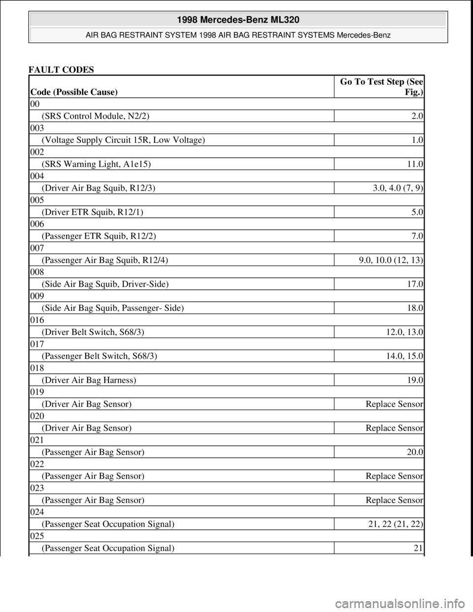
FAULT CODES
Code (Possible Cause)
Go To Test Step (See
Fig.)
00
(SRS Control Module, N2/2)2.0
003
(Voltage Supply Circuit 15R, Low Voltage)1.0
002
(SRS Warning Light, A1e15)11.0
004
(Driver Air Bag Squib, R12/3)3.0, 4.0 (7, 9)
005
(Driver ETR Squib, R12/1)5.0
006
(Passenger ETR Squib, R12/2)7.0
007
(Passenger Air Bag Squib, R12/4)9.0, 10.0 (12, 13)
008
(Side Air Bag Squib, Driver-Side)17.0
009
(Side Air Bag Squib, Passenger- Side)18.0
016
(Driver Belt Switch, S68/3)12.0, 13.0
017
(Passenger Belt Switch, S68/3)14.0, 15.0
018
(Driver Air Bag Harness)19.0
019
(Driver Air Bag Sensor)Replace Sensor
020
(Driver Air Bag Sensor)Replace Sensor
021
(Passenger Air Bag Sensor)20.0
022
(Passenger Air Bag Sensor)Replace Sensor
023
(Passenger Air Bag Sensor)Replace Sensor
024
(Passenger Seat Occupation Signal)21, 22 (21, 22)
025
(Passenger Seat Occupation Signal)21
1998 Mercedes-Benz ML320
AIR BAG RESTRAINT SYSTEM 1998 AIR BAG RESTRAINT SYSTEMS Mercedes-Benz
me
Saturday, October 02, 2010 3:33:14 PMPage 18 © 2006 Mitchell Repair Information Company, LLC.
Page 19 of 4133
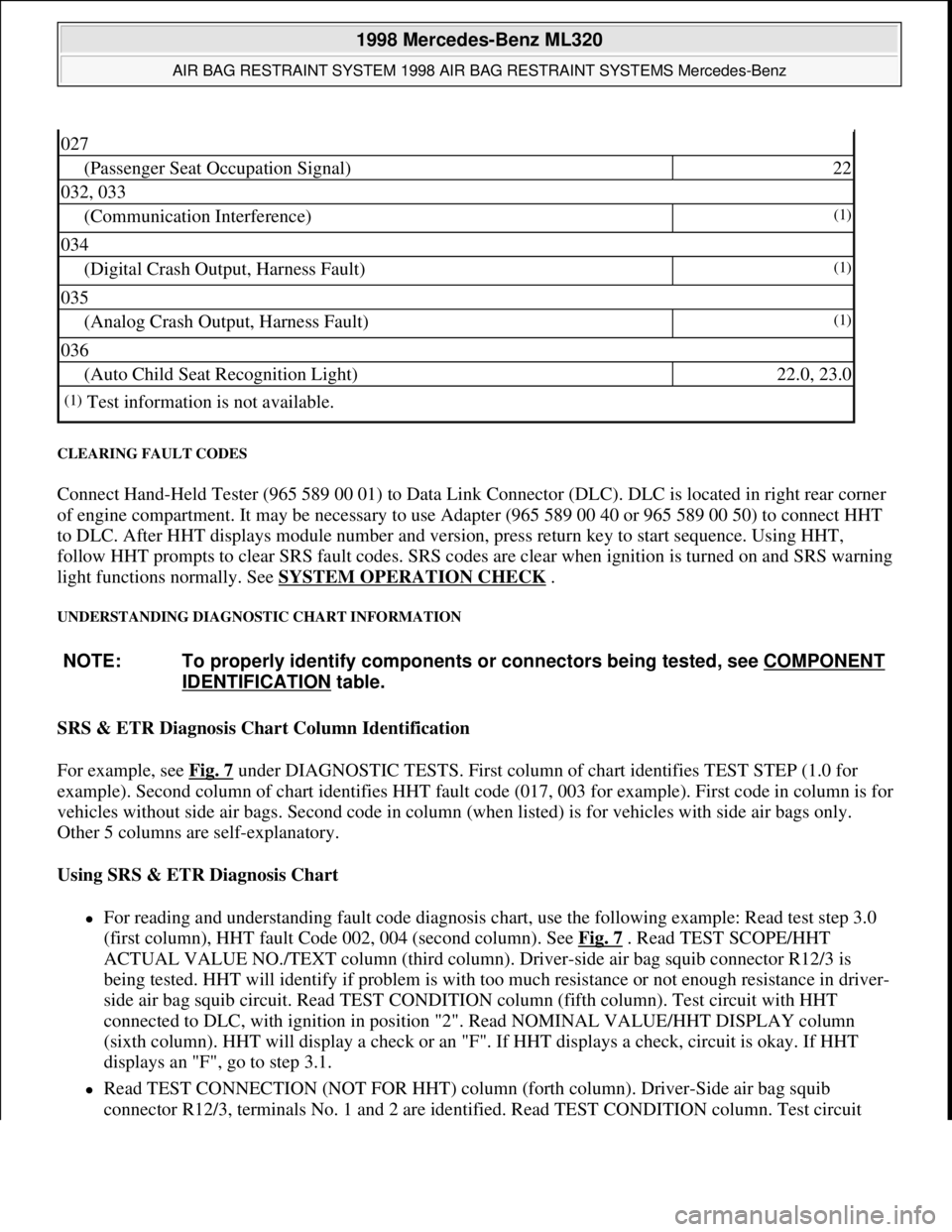
CLEARING FAULT CODES
Connect Hand-Held Tester (965 589 00 01) to Data Link Connector (DLC). DLC is located in right rear corner
of engine compartment. It may be necessary to use Adapter (965 589 00 40 or 965 589 00 50) to connect HHT
to DLC. After HHT displays module number and version, press return key to start sequence. Using HHT,
follow HHT prompts to clear SRS fault codes. SRS codes are clear when ignition is turned on and SRS warning
light functions normally. See SYSTEM OPERATION CHECK
.
UNDERSTANDING DIAGNOSTIC CHART INFORMATION
SRS & ETR Diagnosis Chart Column Identification
For example, see Fig. 7
under DIAGNOSTIC TESTS. First column of chart identifies TEST STEP (1.0 for
example). Second column of chart identifies HHT fault code (017, 003 for example). First code in column is for
vehicles without side air bags. Second code in column (when listed) is for vehicles with side air bags only.
Other 5 columns are self-explanatory.
Using SRS & ETR Diagnosis Chart
For reading and understanding fault code diagnosis chart, use the following example: Read test step 3.0
(first column), HHT fault Code 002, 004 (second column). See Fig. 7
. Read TEST SCOPE/HHT
ACTUAL VALUE NO./TEXT column (third column). Driver-side air bag squib connector R12/3 is
being tested. HHT will identify if problem is with too much resistance or not enough resistance in driver-
side air bag squib circuit. Read TEST CONDITION column (fifth column). Test circuit with HHT
connected to DLC, with ignition in position "2". Read NOMINAL VALUE/HHT DISPLAY column
(sixth column). HHT will display a check or an "F". If HHT displays a check, circuit is okay. If HHT
displays an "F", go to step 3.1.
Read TEST CONNECTION (NOT FOR HHT) column (forth column). Driver-Side air bag squib
connector R12/3, terminals No. 1 and 2 are identified. Read TEST CONDITION column. Test circuit
027
(Passenger Seat Occupation Signal)22
032, 033
(Communication Interference)(1)
034
(Digital Crash Output, Harness Fault)(1)
035
(Analog Crash Output, Harness Fault)(1)
036
(Auto Child Seat Recognition Light)22.0, 23.0
(1)Test information is not available.
NOTE: To properly identify components or connectors being tested, see COMPONENT
IDENTIFICATION table.
1998 Mercedes-Benz ML320
AIR BAG RESTRAINT SYSTEM 1998 AIR BAG RESTRAINT SYSTEMS Mercedes-Benz
me
Saturday, October 02, 2010 3:33:14 PMPage 19 © 2006 Mitchell Repair Information Company, LLC.
Page 20 of 4133
with HHT connected to DLC and ignition key removed. Remove driver-side air bag module. Disconnect
driver-side air bag module squib connector R12/3. Connect Resistance Substitution Unit (124 589 09 63)
to driver-side air bag module squib connector (harness side). Set resistance substitution unit to 2 ohms.
Turn ignition key to position "2". Read NOMINAL VALUE/HHT DISPLAY column. If HHT displays a
check, replace driver-side air bag module. If HHT displays an "F", go to step 3.2.
Read TEST CONNECTION (NOT FOR HHT) column. Horn/air bag clockspring connector A45x1,
terminals No. 1 and 2 are identified. Read TEST CONDITION column. Test circuit with HHT connected
to DLC. Remove ignition key. Connect Resistance Substitution Unit (124 589 09 63 00) to horn/air bag
clockspring connector A45x1. Set resistance substitution unit to 2 ohms. Read NOMINAL VALUE/HHT
DISPLAY column. If HHT displays a check, check horn/air bag clockspring for continuity. Replace
horn/air bag clockspring as necessary. If HHT displays an "F", go to step 3.4.
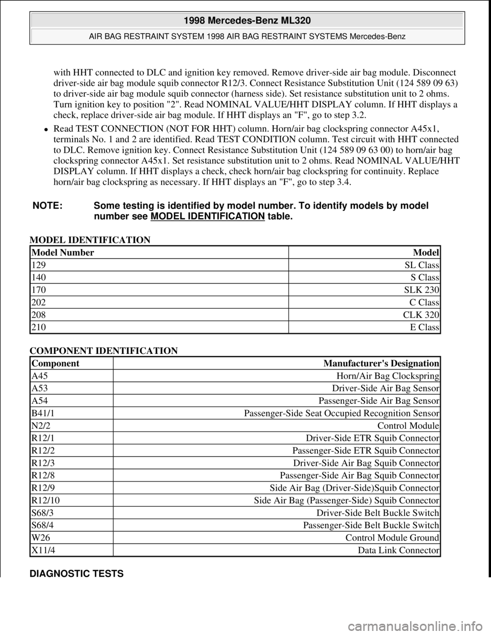
MODEL IDENTIFICATION
COMPONENT IDENTIFICATION
DIAGNOSTIC TESTS NOTE: Some testing is identified by model number. To identify models by model
number see MODEL IDENTIFICATION
table.
Model NumberModel
129SL Class
140S Class
170SLK 230
202C Class
208CLK 320
210E Class
ComponentManufacturer's Designation
A45Horn/Air Bag Clockspring
A53Driver-Side Air Bag Sensor
A54Passenger-Side Air Bag Sensor
B41/1Passenger-Side Seat Occupied Recognition Sensor
N2/2Control Module
R12/1Driver-Side ETR Squib Connector
R12/2Passenger-Side ETR Squib Connector
R12/3Driver-Side Air Bag Squib Connector
R12/8Passenger-Side Air Bag Squib Connector
R12/9Side Air Bag (Driver-Side)Squib Connector
R12/10Side Air Bag (Passenger-Side) Squib Connector
S68/3Driver-Side Belt Buckle Switch
S68/4Passenger-Side Belt Buckle Switch
W26Control Module Ground
X11/4Data Link Connector
1998 Mercedes-Benz ML320
AIR BAG RESTRAINT SYSTEM 1998 AIR BAG RESTRAINT SYSTEMS Mercedes-Benz
me
Saturday, October 02, 2010 3:33:14 PMPage 20 © 2006 Mitchell Repair Information Company, LLC.
Page 34 of 4133
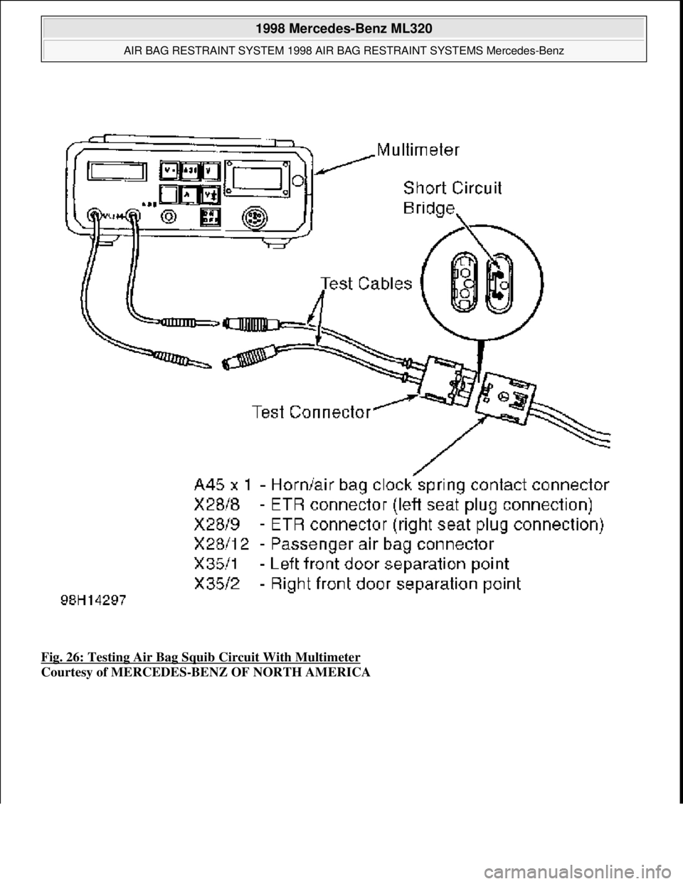
Fig. 26: Testing Air Bag Squi b Circuit With Multimeter
Courtesy of MERCEDES-BENZ OF NORTH AMERICA
1998 Mercedes-Benz ML320
AIR BAG RESTRAINT SYSTEM 1998 AIR BAG RESTRAINT SYSTEMS Mercedes-Benz
me
Saturday, October 02, 2010 3:33:14 PMPage 34 © 2006 Mitchell Repair Information Company, LLC.
Page 35 of 4133
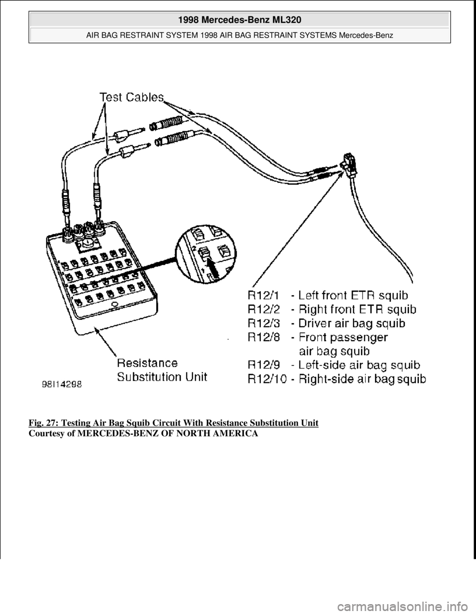
Fig. 27: Testing Air Bag Squib Circuit With Resistance Substitution Unit
Courtesy of MERCEDES-BENZ OF NORTH AMERICA
1998 Mercedes-Benz ML320
AIR BAG RESTRAINT SYSTEM 1998 AIR BAG RESTRAINT SYSTEMS Mercedes-Benz
me
Saturday, October 02, 2010 3:33:14 PMPage 35 © 2006 Mitchell Repair Information Company, LLC.
Page 108 of 4133
58 Restraint systems
Te ch n ica l
data Instruments
and controlsOperationDrivingInstrument
cluster displayPractical hints Car care Index
out after approximately 5 seconds; after the lamp goes
out, the system continues to monitor the components
and circuitry of the airbag system and will indicate a
malfunction by coming on again. If the lamp does not
come on at all or if it fails to extinguish after
approximately 5 seconds or if it comes on thereafter,
a malfunction in the system has been detected.
The following system components are monitored or
undergo a self-check: crash-sensor(s), airbag ignition
circuits, front seat belt buckles, emergency tensioning
retractors, seat sensor.
Initially, when the key is turned from steering lock
position 0 to positions 1 or 2, malfunctions in the
crash-sensor are detected and indicated (the “SRS”
indicator lamp stays on longer than 5 seconds or does
not come on).
Have the system checked at your authorized
Mercedes-Benz Light Truck Center immediately.In the operational mode, after the indicator lamp has
gone out following the initial check, interruptions or
short circuits in the airbag ignition circuit and in the
driver and front passenger seat belt buckle harnesses,
and low voltage in the entire system are detected and
indicated.
Wa r n i n g !
In the event a malfunction of the “SRS” is indicated
as outlined above, the “SRS” may not be
operational. For your safety, we strongly
recommend that you visit an authorized
Mercedes-Benz Light Truck Center immediately to
have the system checked; otherwise the “SRS” may
not be activated when needed in an accident, which
could result in serious or fatal injury, or it might
deploy unexpectedly and unnecessarily which
could also result in injury.
Page 209 of 4133
159 Tele Aid
Te ch n ica l
data Instruments
and controlsOperationDrivingInstrument
cluster displayPractical hints Car care Index Info Services (optional, except Canada)
Info Services categories include news, sports, stocks,
weather and calendar reminders. Choices can be
selected via www.mbusa.com or by calling 1-800-FOR-
MERcedes.
To request Info Services press the TEL button and then
the SVC soft key on the MCS unit. Then select UPDT
soft key. “NEW INFO SERVICE REQUEST
TRANSMITTED” will appear in the MCS display and call
status messages will appear in the MCS display.
Once information is available, the message “NEW INFO
RECEIVED READ LATER WHEN STOPPED?” will appear.
Select “Yes”. With the vehicle stopped in a safe location
press TEL button, SVC soft key to read messages.Important!
Tele Aid utilizes the cellular network for
communication and the GPS (Global Positioning
System) satellites for vehicle location. If either of these
signals are unavailable, the Tele Aid system may not
function and if this occurs, assistance must be
summoned by other means.
Wa r n i n g !
The Tele Aid control unit is located under the front
passenger seat. If there is accumulation of water or
other liquid in this area, the Tele Aid control unit
could suffer an electrical short circuit making the
system inoperative. In this case the indicator lamp
in the “SOS” button will not illuminate during or
will remain illuminated after the system self-check.
Have the system checked at the nearest
Mercedes-Benz Light Truck Center as soon as
possible.
Page 269 of 4133
219 Malfunction and indicator lamps
Te ch n ica l
data Instruments
and controlsOperation DrivingInstrument
cluster displayPractical hints Car care Index Brake warning lamp
When the brake warning lamp appears
while the engine is running, this means:
•there is insufficient brake fluid in the reservoir
(engine running and parking brake released), or
•the parking brake is set (engine running)
•the electronic brake proportioning (EBP) system is
malfunctioning.
Note:
If you find that the minimum mark on the brake fluid
reservoir is reached, have the brake system checked for
brake pad thickness and leaks.Supplemental restraint system (SRS) indicator lamp
The operational readiness of the airbag
system is verified by the indicator lamp
“SRS” in the instrument cluster when
turning the key in steering lock to position 1 or 2. If no
fault is detected, the lamp will go out after
approximately 5 seconds; after the lamp goes out, the
system continues to monitor the components and
circuitry of the airbag system and will indicate a
malfunction by coming on again.
See page 56 for notes on airbags, page 55 for belt
tensioners, and page 65 for infant and child seat
restraints.
Wa r n i n g !
Driving with the brake warning lamp illuminated
can result in an accident. Have your brake system
checked immediately if the brake warning lamp
stays on. Don’t add brake fluid before checking the
brake system. Overfilling the brake fluid reservoir
can result in spilling brake fluid on hot engine
parts and the brake fluid catching fire. You can be
seriously burned.BRAKE
Wa r n i n g !
In the event a malfunction of the “SRS” is indicated
as outlined above, the “SRS” may not be
operational. For your safety, we strongly
recommend that you visit an authorized
Mercedes-Benz Light Truck Center immediately to
have the system checked; otherwise the “SRS” may
not be activated when needed in an accident, which
could result in serious or fatal injury, or it might
deploy unexpectedly and unnecessarily which
could also result in injury.SRS