Page 695 of 4133
228
First aid kit
Te ch n ica l
data
Instruments
and controls Operation Driving
Instrument
cluster display Practical hints
Car care Index
First aid kit
All except model ML 55 AMG:
The first aid kit is located behind the cover in the left
rear cargo compartment trim panel.
Turn both handles (1) left and open cover.
Model ML 55 AMG:
The first aid kit is stored inside the spare wheel cover
located in the cargo compartment.
Open buckles and remove spare wheel cover,
see page 242. Fuses
Before replacing a blown fuse, determine the cause of
the short circuit.
Spare fuses and a special fuse puller are supplied inside
the fuse box cover. Observe amperage and color of fuse.
Always use a new fuse for replacement. Never attempt to
repair or bridge a blown fuse.
A fuse chart can be found inside the corresponding fuse
box cover.
Page 719 of 4133
252
Battery
Te ch n ica l
data
Instruments
and controls Operation Driving
Instrument
cluster display Practical hints
Car care Index
Therefore, we strongly recommend that you have the
battery charge checked frequently, and corrected if
necessary, especially if you use the vehicle less than
approximately 200 miles (300 km) per month,
mostly for short distance trips, or if it is not used for
long periods of time.
Only charge a battery with a battery charger after the
battery has been disconnected from the vehicle’s
electrical circuit.
Always disconnect the battery negative lead first and
connect last.
When removing and connecting the battery, always
make sure that all electrical consumers are off and the
key is in steering lock position 0. The battery must
always be securely installed when the vehicle is in
operation. During removal and installation always
protect the disconnected battery positive (+) terminal
with the cover attached to the battery.
While the engine is running the battery terminal clamps
must not be loosened or detached, otherwise the
generator and other electronic components would be
damaged. Note:
After reconnecting the battery also set the clock in
instrument cluster (see page 80), set date in trip
computer (see page 83), resynchronize the sliding / pop-
up roof (see page 272), the Skyview Top (see page 273)
and the electronic stability program (ESP) (see
page 206).
Battery recycling
Batteries contain material that can harm the
environment with improper disposal.
Large 12 Volt storage batteries contain lead.
Recycling of batteries is the preferred method of
disposal.
Many states require sellers of batteries to accept old
batteries for recycling.
Page 727 of 4133
260
Exterior lamps
Te ch n ica l
data
Instruments
and controls Operation Driving
Instrument
cluster display Practical hints
Car care Index
Exterior lamps
Headlamp adjustment
Correct headlamp adjustment is extremely important.
Check and readjust headlamps at regular intervals and
when a bulb has been replaced.
For adjusting headlamp aim see page 268. Replacing bulbs
To prevent a possible electrical short circuit, switch off
lamp prior to replacing a bulb.
When replacing bulbs, install only 12 volt bulbs with
the specified watt rating.
When replacing halogen bulbs do not touch glass
portion of bulb with bare hands. Use plain paper or a
clean cloth.
Wa r n i n g !
Bulbs and bulb holders can be very hot. Allow the
lamp to cool down before changing a bulb.
Halogen lamps contain pressurized gas. A bulb can
explode if you: • touch or move it when hot,
•drop the bulb,
•scratch the bulb.Wear eye and hand protection.
Wa r n i n g !
Because of high voltage in Xenon lamps, it is
dangerous to replace the bulb of repair the lamp
and its components. We recommend that you have
such work done by a qualified technician.
Page 977 of 4133
173 Controls in detail
Useful features
Emergency calls
An emergency call is initiated automatical-
ly:�
following an accident in which the
emergency tensioning detractors
(ETDs) or airbags deploy,
�
if the anti-theft alarm or the tow-away
alarm stays on for more than
20 seconds. See anti-theft alarm sys-
tem (
�page 83) and tow-away alarm
(
�page 84).
An emergency call can also be initiated
manually by opening the cover next to the
inside rear view mirror labeled SOS, then
briefly pressing the button located under
the cover. See below for instructions on
initiating an emergency call manually.
Warning!
G
The Tele Aid control unit is located under
the front passenger seat. If there is accumu-
lation of water or other liquid in this area,
the Tele Aid control unit could suffer an
electrical short circuit making the system in-
operative. In this case the indicator lamp in
the SOS button will not illuminate during or
will remain illuminated after the system
self-check. Have the system checked at the
nearest Mercedes-Benz Light Truck Center
as soon as possible.
If the indicator lamps in the SOS button, in
the Roadside Assistance button and / or in
the Information button do not come on dur-
ing the system self-check or if any of these
indicators remain illuminated constantly in
red and / or the message
TELE AID -
VISIT WORKSHOP
is displayed in the MCS
display after the system self-check, a mal-
function in the system has been detected.
If a malfunction is indicated as outlined
above, the system may not operate as ex-
pected. Have the system checked at the
nearest Mercedes-Benz Light Truck Center
as soon as possible.
Page 1071 of 4133
267 Practical hints
Replacing bulbs
Rear lamps Notes on bulb replacement
�
Use only 12-volt bulbs of the same type
and with the specified watt rating.
�
Switch lights off before changing a bulb
to prevent short circuits.
�
Always use a clean lint-free cloth when
handling bulbs.
�
Your hands should be dry and free of oil
and grease.
�
If the newly installed bulb does not light
up, visit an authorized Mercedes-Benz
Light Truck Center.
�
Have the LEDs and bulbs for the follow-
ing lamps replaced by an authorized
Mercedes-Benz Light Truck Center:�
Additional turn signals in the exteri-
or rear view mirrors
�
Bi-Xenon lamps*
�
Front fog lamps (vehicles with sport
package)*
Lamp
Type
6
Brake lamp
1073
(32 cp bulb)
7
Backup lamp
1073
(32 cp bulb)
8
Turn signal lamp
PY 21 W
9
Tail, parking and
standing lamp
Rear fog lamp, driv-
er’s side
P 21 / 4 W
a
Side marker lamp
W5W
b
High mounted brake
lamp
1073
(32 cp bulb)
c
License plate lamps
C 5 W
Warning!
G
Keep bulbs out of reach of children.
Bulbs and bulb sockets can be very hot. Al-
low the lamp to cool down before changing
a bulb.
Halogen lamps contain pressurized gas. A
bulb can explode if you:�
touch or move it when hot
�
drop the bulb
�
scratch the bulb
Wear eye and hand protection.
Because of high voltage in xenon lamps, it is
dangerous to replace the bulb or repair the
lamp and its components. We recommend
that you have such work done by a qualified
technician.
Page 1082 of 4133
278 Practical hintsBattery
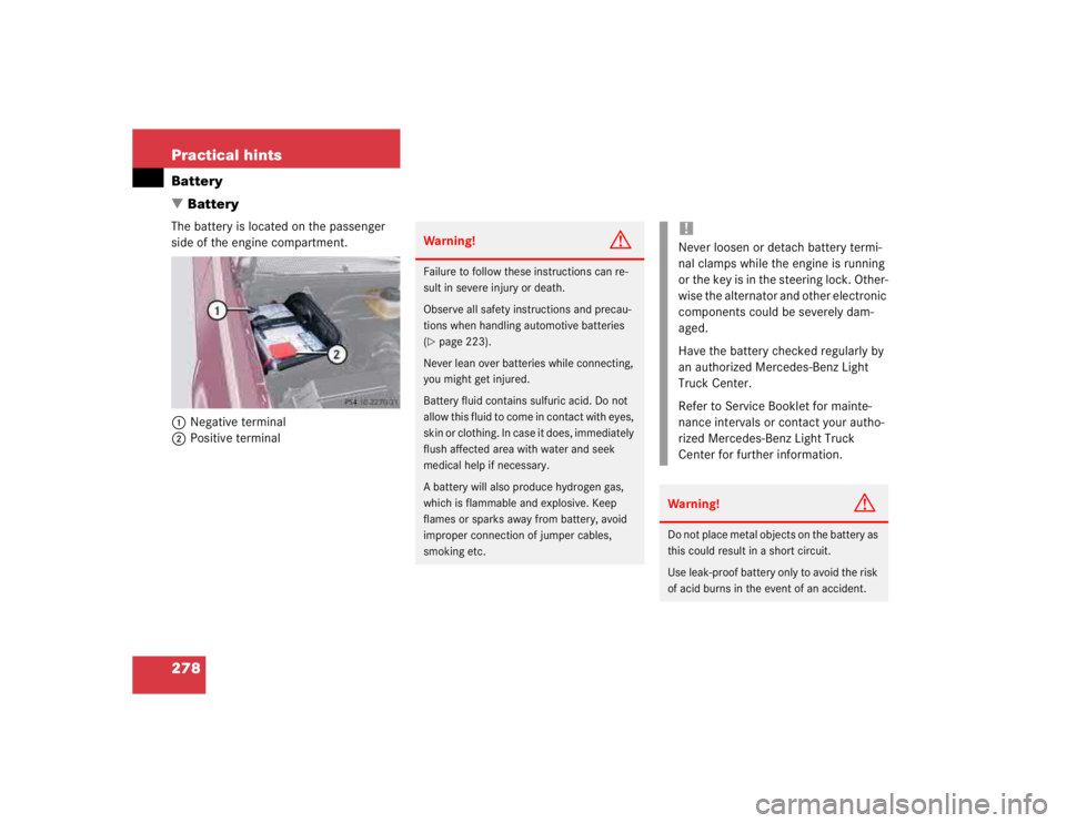
�BatteryThe battery is located on the passenger
side of the engine compartment.
1Negative terminal
2Positive terminal
Warning!
G
Failure to follow these instructions can re-
sult in severe injury or death.
Observe all safety instructions and precau-
tions when handling automotive batteries
(�page 223).
Never lean over batteries while connecting,
you might get injured.
Battery fluid contains sulfuric acid. Do not
allow this fluid to come in contact with eyes,
skin or clothing. In case it does, immediately
flush affected area with water and seek
medical help if necessary.
A battery will also produce hydrogen gas,
which is flammable and explosive. Keep
flames or sparks away from battery, avoid
improper connection of jumper cables,
smoking etc.
!Never loosen or detach battery termi-
nal clamps while the engine is running
or the key is in the steering lock. Other-
wise the alternator and other electronic
components could be severely dam-
aged.
Have the battery checked regularly by
an authorized Mercedes-Benz Light
Truck Center.
Refer to Service Booklet for mainte-
nance intervals or contact your autho-
rized Mercedes-Benz Light Truck
Center for further information.Warning!
G
Do not place metal objects on the battery as
this could result in a short circuit.
Use leak-proof battery only to avoid the risk
of acid burns in the event of an accident.
Page 1231 of 4133
Operation
In selector lever position "P" and "N" the starter lockout contact (Y3/6s1) is actuated by a cam track which is
located on the detent plate. See Fig. 29
.
The permanent magnet (47) is moved away from the dry-reed contact (48). The dry-reed contact (48) is opened.
The ETC control module (N15/3) receives an electric signal. The circuit to the starter in the selector lever
position "P" and "N" is closed.
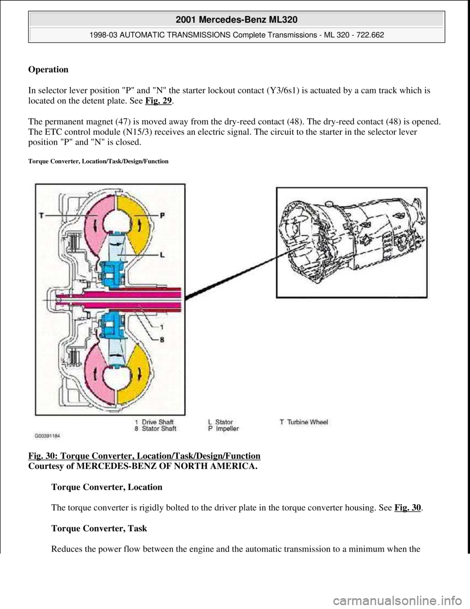
Torque Converter, Location/Task/Design/Function
Fig. 30: Torque Converter, Location/Task/Design/Function
Courtesy of MERCEDES-BENZ OF NORTH AMERICA.
Torque Converter, Location
The torque converter is rigidly bolted to the driver plate in the torque converter housing. See Fig. 30
.
Torque Converter, Task
Reduces the power flow between the en
gine and the automatic transmission to a minimum when the
2001 Mercedes-Benz ML320
1998-03 AUTOMATIC TRANSMISSIONS Complete Transmissions - ML 320 - 722.662
me
Saturday, October 02, 2010 3:15:26 PMPage 62 © 2006 Mitchell Repair Information Company, LLC.
Page 1458 of 4133
Fig. 162: Function Of Locking Of Selector Lever Position "P"
Courtesy of MERCEDES-BENZ OF NORTH AMERICA.
One of the functions of the shift lock is to lock the selector lever in position "P". The selector lever is locked
electronically. See Fig. 162
.
The selector lever remains disabled in position "P", if the brake is not operated or there is no power supply to
the electronic selector lever module control module (N15/5) (circuit 87).
The electronic selector lever module control module (N15/5) actuates the R/P lock solenoid valve (89) from the
2001 Mercedes-Benz ML320
1998-03 AUTOMATIC TRANSMISSIONS Complete Transmissions - ML 320 - 722.662
me
Saturday, October 02, 2010 3:15:30 PMPage 289 © 2006 Mitchell Repair Information Company, LLC.