1997 MERCEDES-BENZ ML500 Circuit 15
[x] Cancel search: Circuit 15Page 1523 of 4133
![MERCEDES-BENZ ML500 1997 Complete Repair Manual Function prerequisites:
Circuit 15 ON
Function
The headlamp cleaning system is switched on by pressing the SRA [HCS] switch (S4/1) .
The corresponding input of the Extended Activity M MERCEDES-BENZ ML500 1997 Complete Repair Manual Function prerequisites:
Circuit 15 ON
Function
The headlamp cleaning system is switched on by pressing the SRA [HCS] switch (S4/1) .
The corresponding input of the Extended Activity M](/manual-img/4/57308/w960_57308-1522.png)
Function prerequisites:
Circuit 15 ON
Function
The headlamp cleaning system is switched on by pressing the SRA [HCS] switch (S4/1) .
The corresponding input of the Extended Activity Module (EAM) (N10/1) , which receives the input
from the switch, sends the signal to relay 5 (F2k5) .
The relay switches circuit 30 , for a duty cycle of approx. 1 second, through to the HCS pump (M5/2) .
The HCS pump (M5/2) builds up pressure in the washing water line.
The water pressure acts against the return springs of the telescopic nozzles.
The telescopic nozzles extend and spray washing water onto the headlamp glass.
After the duty cycle, the pressure in the washing water line drops again and the telescopic nozzles move
back to their starting position due to spring load.
Pressing the SRA [HCS] switch (S4/1) again during an ongoing headlamp cleaning cycle has no effect.
A further cleaning cycle can only be initiated after the previous cycle has ended.
TABLE OF CONTENTS, FUNCTION DESCRIPTION FOR HEADLAMP CLEANING SYSTEM (HCS) - GF82.15-P-0998GHZ
MODEL 163 as of 01.09.01 with CODE (600a) headlamp cleaning system
FUNCTION OF HEADLAMP CLEANING SYSTEM TELESCOPIC NOZZLES - GF82.15-P-2100-04GH
After the HCS pump (M5/2) has started to operate, pressure builds up in the washing water line for approx. 1
Headlamp cleaning system (HCS),
location of components GF82.15-P-0002-
03GH
Telescopic nozzles for headlamp
cleaning system,
location/task/design/function GF82.15-P-2100GH
Extended Activity Module,
location/task/design GF54.21-P-4107GK
Headlamp cleaning system
(HCS), function GF82.15-P-0002GH
Headlamp cleaning system
(HCS), location of components GF82.15-P-0002-
03GH
Survey of system components
for headlamp cleaning system
(HCS), location/task/design/
function GF82.15-P-9998GHZ
2001 Mercedes-Benz ML320
1998-2005 ACCESSORIES & BODY, CAB Electrical System - Body - 163 Chassis
me
Saturday, October 02, 2010 3:30:04 PMPage 28 © 2006 Mitchell Repair Information Company, LLC.
Page 1531 of 4133
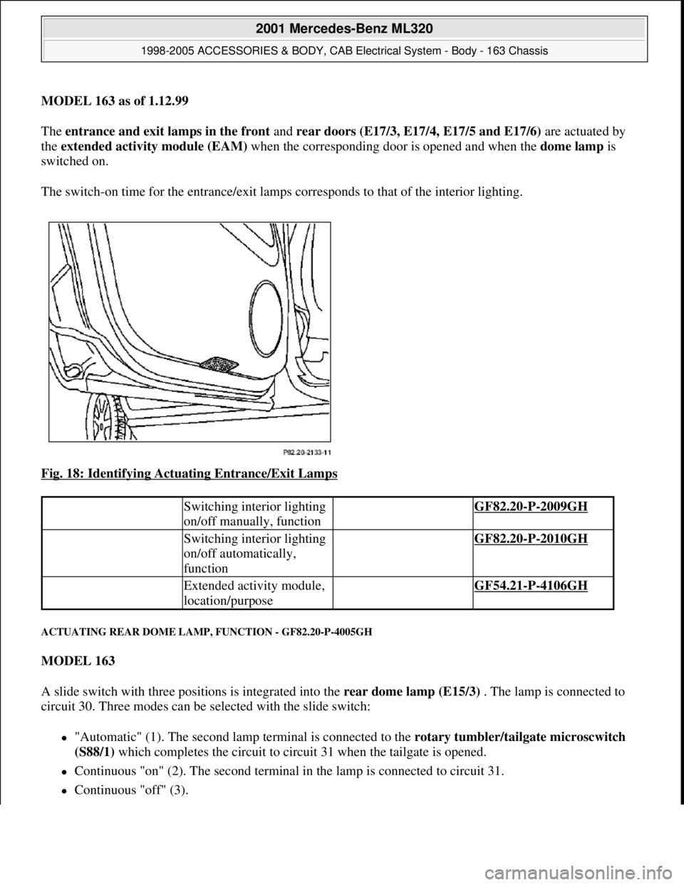
MODEL 163 as of 1.12.99
The entrance and exit lamps in the front and rear doors (E17/3, E17/4, E17/5 and E17/6) are actuated by
the extended activity module (EAM) when the corresponding door is opened and when the dome lamp is
switched on.
The switch-on time for the entrance/exit lamps corresponds to that of the interior lighting.
Fig. 18: Identifying Actuating Entrance/Exit Lamps
ACTUATING REAR DOME LAMP, FUNCTION - GF82.20-P-4005GH
MODEL 163
A slide switch with three positions is integrated into the rear dome lamp (E15/3) . The lamp is connected to
circuit 30. Three modes can be selected with the slide switch:
"Automatic" (1). The second lamp terminal is connected to the rotary tumbler/tailgate microscwitch
(S88/1) which completes the circuit to circuit 31 when the tailgate is opened.
Continuous "on" (2). The second terminal in the lamp is connected to circuit 31.
Continuous "off" (3).
Switching interior lighting
on/off manually, function GF82.20-P-2009GH
Switching interior lighting
on/off automatically,
function GF82.20-P-2010GH
Extended activity module,
location/purpose GF54.21-P-4106GH
2001 Mercedes-Benz ML320
1998-2005 ACCESSORIES & BODY, CAB Electrical System - Body - 163 Chassis
me
Saturday, October 02, 2010 3:30:04 PMPage 36 © 2006 Mitchell Repair Information Company, LLC.
Page 1537 of 4133
REAR INTERMITTENT WIPE - FUNCTION - GF82.30-P-3001GH
MODEL 163 Applicable to 31.8.00
The rear intermittent wipe function is activated by placing the rear wiper/washer switch (S78) in the up
position. With the switch in this position, the All Activity Module (AAM) (N10) activates the tailgate wiper
motor (M6/4) every five seconds.
A relay circuit in the wiper motor stops the wiper arm in the park position.
REAR INTERMITTENT WIPE - FUNCTION - GF82.30-P-3001GK
MODEL 163 Applicable as of 1.9.00
The rear intermittent wipe function is linked, among other things, to the operation of the windshield wiper
system. It will therefore be described in relation to the position of the combination switch (S4):
Combination switch (S4) position: OFF
The rear wiper is powered from KI. 15R: ON by operating the rear wiper/washer switch (S78) . Switching
on the wiper illuminates the LED on the rear wiper/washer switch (S78) and immediately causes the wiper arm
to perform one complete sweep before switching to intermittent wiping.
When the vehicle is traveling at speeds of
less than 100 km/h the wipe interval is 10 seconds
of 100 km/h or more the wipe interval is 5 seconds .
The wiper is turned off by reactivating the wiper/washer switch.
Combination switch (S4) position: Wiper speed 1 or 2
The rear wiper is activated from KI. 15R: ON using the rear wiper/washer switch (S78) .
Switching on the wiper illuminates the LED on the rear wiper/ washer switch (S78) and immediately
causes the wiper arm to perform one complete sweep before switching to intermittent wiping. The wipe
interval is 5 seconds .
Survey on wiper system
components (WS), location/
purpose/design/function GF82.30-P-9998GH
Rear wiper/washer switch GF82.30-P-4105GH
All Activity ModuleTo 30.11.99GF54.21-P-4100GH
As of 1.12.99GF54.21-P-4100GK
Tailgate wiper motor GF82.30-P-4105GH
2001 Mercedes-Benz ML320
1998-2005 ACCESSORIES & BODY, CAB Electrical System - Body - 163 Chassis
me
Saturday, October 02, 2010 3:30:04 PMPage 42 © 2006 Mitchell Repair Information Company, LLC.
Page 1540 of 4133
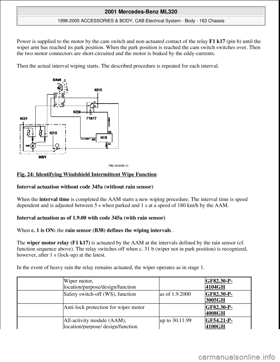
Power is supplied to the motor by the cam switch and non-actuated contact of the relay F1 k17(pin b) until the
wiper arm has reached its park position. When the park position is reached the cam switch switches over. Then
the two motor connectors are short-circuited and the motor is braked by the eddy-currents.
Then the actual interval wiping starts. The described procedure is repeated for each interval.
Fig. 24: Identifying Windshield Intermittent Wipe Function
Interval actuation without code 345a (without rain sensor)
When the interval time is completed the AAM starts a new wiping procedure. The interval time is speed
dependent and is adjusted between 5 s when parked and 1 s at a speed of 180 km/h by the AAM.
Interval actuation as of 1.9.00 with code 345a (with rain sensor)
When c. 1 is ON: the rain sensor (B38) defines the wiping intervals .
The wiper motor relay (F1 k17) is actuated by the AAM at the intervals defined by the rain sensor (cf.
function sequence above). The relay switches off when c. 31 b (wiper not in park position) is recognized,
however, after 1 s (lock-up) at the latest.
In the event of heavy rain the relay remains actuated, the wiper operates as in stage 1.
Wiper motor,
location/purpose/design/function GF82.30-P-
4104GH
Safety switch-off (WS), functionas of 1.9.2000GF82.30-P-
3005GH
Anti-lock protection for wiper motor GF82.30-P-
4008GH
All-activity module (AAM),
location/purpose/ design/functionup to 30.11.99GF54.21-P-
4100GH
2001 Mercedes-Benz ML320
1998-2005 ACCESSORIES & BODY, CAB Electrical System - Body - 163 Chassis
me
Saturday, October 02, 2010 3:30:04 PMPage 45 © 2006 Mitchell Repair Information Company, LLC.
Page 1541 of 4133
WIPER, FUNCTION - GF82.30-P-3004GH
MODEL 163
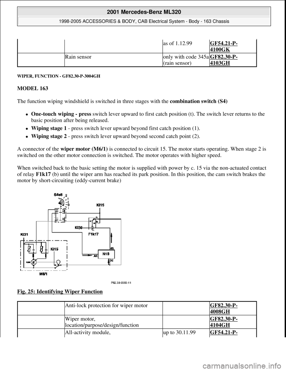
The function wiping windshield is switched in three stages with the combination switch (S4)
One-touch wiping - press switch lever upward to first catch position (t). The switch lever returns to the
basic position after being released.
Wiping stage 1 - press switch lever upward beyond first catch position (1).
Wiping stage 2 - press switch lever upward beyond second catch point (2).
A connector of the wiper motor (M6/1) is connected to circuit 15. The motor starts operating. When stage 2 is
switched on the other motor connection is switched. The motor operates with higher speed.
When switched back to the basic setting the motor is supplied with power by c. 15 via the non-actuated contact
of relay F1k17 (b) until the wiper arm has reached its park position. In this position, the cam switch brakes the
motor by short-circuiting (eddy-current brake)
Fig. 25: Identifying Wiper Function
as of 1.12.99GF54.21-P-
4100GK
Rain sensoronly with code 345a
(rain sensor)GF82.30-P-
4103GH
Anti-lock protection for wiper motor GF82.30-P-
4008GH
Wiper motor,
location/purpose/design/function GF82.30-P-
4104GH
All-activity module, up to 30.11.99GF54.21-P-
2001 Mercedes-Benz ML320
1998-2005 ACCESSORIES & BODY, CAB Electrical System - Body - 163 Chassis
me
Saturday, October 02, 2010 3:30:04 PMPage 46 © 2006 Mitchell Repair Information Company, LLC.
Page 1545 of 4133
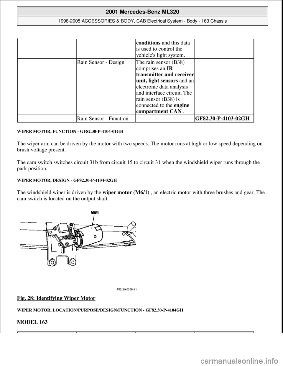
WIPER MOTOR, FUNCTION - GF82.30-P-4104-01GH
The wiper arm can be driven by the motor with two speeds. The motor runs at high or low speed depending on
brush voltage present.
The cam switch switches circuit 31b from circuit 15 to circuit 31 when the windshield wiper runs through the
park position.
WIPER MOTOR, DESIGN - GF82.30-P-4104-02GH
The windshield wiper is driven by the wiper motor (M6/1) , an electric motor with three brushes and gear. The
cam switch is located on the output shaft.
Fig. 28: Identifying Wiper Motor
WIPER MOTOR, LOCATION/PURPOSE/DESIGN/FUNCTION - GF82.30-P-4104GH
MODEL 163
conditions and this data
is used to control the
vehicle's light system.
Rain Sensor - DesignThe rain sensor (B38)
comprises an IR
transmitter and receiver
unit, light sensorsand an
electronic data analysis
and interface circuit. The
rain sensor (B38) is
connected to the engine
compartment CAN .
Rain Sensor - Function GF82.30-P-4103-02GH
2001 Mercedes-Benz ML320
1998-2005 ACCESSORIES & BODY, CAB Electrical System - Body - 163 Chassis
me
Saturday, October 02, 2010 3:30:05 PMPage 50 © 2006 Mitchell Repair Information Company, LLC.
Page 1547 of 4133
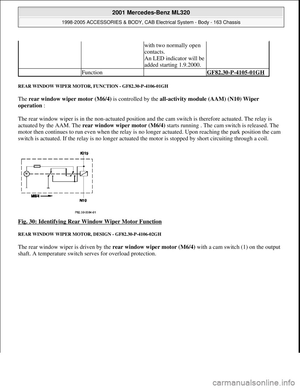
REAR WINDOW WIPER MOTOR, FUNCTION - GF82.30-P-4106-01GH
The rear window wiper motor (M6/4) is controlled by the all-activity module (AAM) (N10) Wiper
operation :
The rear window wiper is in the non-actuated position and the cam switch is therefore actuated. The relay is
actuated by the AAM. The rear window wiper motor (M6/4) starts running . The cam switch is released. The
motor then continues to run even when the relay is no longer actuated. Upon reaching the park position the cam
switch is actuated. If the relay is no longer actuated the motor is stopped by short circuiting through a coil.
Fig. 30: Identifying Rear Window Wiper Motor Function
REAR WINDOW WIPER MOTOR, DESIGN - GF82.30-P-4106-02GH
The rear window wiper is driven by the rear window wiper motor (M6/4) with a cam switch (1) on the output
shaft. A temperature switch serves for overload protection.
with two normally open
contacts.
An LED indicator will be
added starting 1.9.2000.
Function GF82.30-P-4105-01GH
2001 Mercedes-Benz ML320
1998-2005 ACCESSORIES & BODY, CAB Electrical System - Body - 163 Chassis
me
Saturday, October 02, 2010 3:30:05 PMPage 52 © 2006 Mitchell Repair Information Company, LLC.
Page 1549 of 4133
REAR WASH - FUNCTION - GF82.35-P-3001GH
MODEL 163
The rear wash function is activated by placing the rear wiper/ washer switch (S78) in the down position. The
switch contact connects the tailgate washer pump (M5/3) to terminal 15. The All Activity Module (AAM)
(N10) detects the activation of the switch via the second switch contact and actuates the tailgate washer motor
(M6/4) and the tailgate washer fluid pump (M5/3) for as long as the switch is on.
The activation time for the tailgate washer fluid pump (M5/3)is limited to 15 sec. To reactivate the pump, the
button must be pressed again.
To wipe window dry, the tailgate wiper motor (M6/4) remains activated for five seconds after the switch is
released.
As described for the rear wiper function, a relay circuit in the wiper motor stops the wiper in the park position .
WINDSHIELD WASH - FUNCTION - GF82.35-P-3002GH
MODEL 163
The windshield wash function is activated by pulling the combination switch, washer switch (S4s4) towards
the steering column. The switch contact connects the washer pump (M5/1) to terminal 15R. The All Activity
Module (AAM) (N10) detects switch activation via an input that measures power supply to the washer pump
(M5/1).
If the combination switch (S4) is in the Wiper Off or Intermittent position, the AAM activates the wiper
motor (M6/1) via rela
y F1k17 . To wipe windshield dry, the motor continues to operate after the switch has
Rear window washer
pump, location /
purpose / design /
function GF82.35-P-4103GH
Table of contents,
function description,
wiper system (WS) GF82.30-P-0998GH
Rear Wipe GF82.30-P-3004GH
Rear Wiper/Washer
Switch GF82.30-P-4105GH
Tailgate Wiper Motor GF82.30-P-4106GH
Tailgate Washer Pump GF82.35-P-4103GH
All Activity ModuleTo 30.11.99GF54.21-P-4100GH
As of 1.12.99GF54.21-P-4100GK
2001 Mercedes-Benz ML320
1998-2005 ACCESSORIES & BODY, CAB Electrical System - Body - 163 Chassis
me
Saturday, October 02, 2010 3:30:05 PMPage 54 © 2006 Mitchell Repair Information Company, LLC.