1997 MERCEDES-BENZ ML500 Circuit 15
[x] Cancel search: Circuit 15Page 1506 of 4133
Short-circuit resistance
Zero potential connection of components
No oxidation
Low weight of fiber optical cable
Minimum diameter of wiring harness
The digital data bus (D2B) has a closed ring structure. The communication and data components are arranged
here in a distributor line (in-series circuit). This arrangement is type specific and is illustrated by way of an
example on model 220 as follows:
Radio (A2)
CD player with changer (in trunk) (A2/6), with code (819) 6-disc CD changer
Sound amplifier (A2/13), with code (810) Sound System
Voice control system control unit (A35/11), with code (813) voice control system (VCS)
Telephone and TELE AID transmitter/receiver, D2B (A35/17), with code (855) TELE AID
Data transfer is conducted here in one direction only, i.e. the optical pulses for the voice control system control
unit (A35/11), for vehicles with code (813) voice control system (VCS), on model 220 pass through all
components connected to the ring, before arriving at the target components.
When the system is first put into operation, a system test is performed. In doing so the individual components
and their sequence in the ring structure of the Digital Data Bus (D2B) are registered by the component with the
master function.
A type-specific sequence is stored ex-factory. In turn, the storing of a sequence ex-factory means: if the radio
(A2) is taken from one model series and installed into another one, then during a system test the different
sequence of the components and an error message are filed in the diagnostic trouble code memory.
An error message is also filed if the radio (A2) is exchanged within a model series with different equipment
components. The system goes to the operational state regardless of the error message. STAR DIAGNOSIS
enables the sequence of the components to be subsequently altered in the Digital Data Bus (D2B).
The Digital Data Bus (D2B) is diagnosis capable via the data link connector (X11/4), except for models 129
and 202.
The operating principle of the Digital Data Bus (D2B) is the same for all model series; all that changes is the
sequence of components depending on the national version and equipment specification.
TABLE OF CONTENTS, FUNCTION DESCRIPTION OF DIGITAL DATA BUS (D2B) - GF82.00-P-0999ZZ
MODEL 129 as of 1.6.98, 163, 168 as of 1.9.98, 170, 202 as of 1.6.98, 203, 208, 210 as of 1.6.98, 215, 220
Data transfer, function GF82.00-P-2000A
2001 Mercedes-Benz ML320
1998-2005 ACCESSORIES & BODY, CAB Electrical System - Body - 163 Chassis
me
Saturday, October 02, 2010 3:30:04 PMPage 11 © 2006 Mitchell Repair Information Company, LLC.
Page 1507 of 4133
DATA TRANSFER, FUNCTION - GF82.00-P-2000A
MODEL 129 as of 1.6.98, 163, 168 as of 1.9.98, 170, 202 as of 1.6.98, 203, 208, 210 as of 1.6.98, 215, 220
The Digital Data Bus (D2B) contains the master unit, e.g. the radio (A2) except for model 129, and model 202,
which triggers all the components in the Digital Data Bus system (D2B). The master unit also serves as an
interface (Gateway) to the CAN interior (CAN-B). For this purpose, signals arriving at the master unit are
converted so that they can be transmitted from the Digital Data Bus (D2B) to the CAN interior (CAN B) and
vice versa. Moreover, the master unit serves as a timing circuit which provides the clock pulse with which the
information frames are transferred on the Digital Data Bus (D2B). A frame consists of 2 subframes. A series of
many data frames contains the complete information for proper operation of the components located at the
Digital Data Bus (D2B). The conversion of optical pulses into electrical signals and vice versa is done by
transmitter and receiver diodes, that are integrated into each component. Each of the components receives or
transmits the electrical signals from the chip of the Digital Data Bus system (D2B) as a "D2B log". Source data
and control data are transmitted.
The source data are transferred synchronously, for example as present on a music CD, as 32 bit blocks into the
subframes. By contrast, control data are transferred asynchronously. They are divided up (2 bits per subframe)
and distributed over several subframes. The control data are provided with an address, which indicates for
which components the data are intended in the Digital Data Bus (D2B). The individual data packages are joined
together again in the components and they can then be processed. A data frame can therefore contain highly
differing types of information (source and control data from all components mounted in the digital data bus
(D2B)). The transmission and reception diodes as well as the digital data bus (D2B) chip are switched off when
not required in order to reduce the quiescent current (sleep mode). Switch-off is accomplished immediately
when the master unit or circuit 15 is switched off. After restart, the digital data bus system (D2B) can be
activated either by the components or by the master unit by means of an electrical signal in the wake-up line for
optical data transmission.
Regardless whether the information is intended for a component, it feeds an edited light signal back into the
digital data bus (D2B) at full intensity (repeater function).
WAKE-UP, FUNCTION - GF82.00-P-2001A
MODEL 129 as of 1.6.98, 163, 168 as of 1.9.98, 170, 202 as of 1.6.98, 203, 208, 210 as of 1.6.98, 215, 220
Normal wake-up
Digital data bus (D2B), function GF82.00-P-0001A
Data transfer, function GF82.00-P-2000A
Wake-up, function GF82.00-P-2001A
Survey of system components, digital
data bus (D2B),
location/task/design/function GF82.00-P-9999A
Wake-up, function GF82.00-P-2001A
2001 Mercedes-Benz ML320
1998-2005 ACCESSORIES & BODY, CAB Electrical System - Body - 163 Chassis
me
Saturday, October 02, 2010 3:30:04 PMPage 12 © 2006 Mitchell Repair Information Company, LLC.
Page 1508 of 4133
Since the transmitting and receiving diodes along with the digital data bus system's (D2B) chip are
automatically shut off if they are not needed (sleep mode), a wake-up pulse, which activates the system, is
required to start a new data transfer. This is accomplished via the separate wake-up line. For this purpose, the
master unit actuates the wake-up signal (electrical signal), which allows the voltage in the wake-up line to
decrease to a defined value. The chip of the digital data bus system (D2B) in the components recognizes on
account of the duration of the signal that this is a wake-up signal, and the digital data bus (D2B) is then
activated. Therefore the digital data bus (D2B) is then in an activated state. A "wake-up" can take place in a
quiescent system (sleep mode) even without the wake-up pulse of the master unit by activation of a component
located at the digital data bus (D2B).
Wake-up diagnosis
For diagnosis of the wake-up circuit in the components, the master unit can trigger a wake-up diagnosis signal
using STAR DIAGNOSIS and the data link connector (X11/4). This signal differs from the wake-up signal by
the fact that it has a significantly longer duration. The components react to this long wake-up pulse with a signal
on the wake-up line (message to master unit). This allows the master unit to recognize which components have
received the long wake-up pulse. The wake-up diagnosis signal can only be actuated when the digital data bus
(D2B) cannot be activated due to an error. If all components reply to the master unit, then their voltage supply is
correct.
FIBER OPTIC CABLE, LOCATION - GF82.00-P-4000-01GH
Model 163
Components for ECE version
Fiber optical cable,
location/task/functionExcept model 208.4GF82.00-P-4000A
2001 Mercedes-Benz ML320
1998-2005 ACCESSORIES & BODY, CAB Electrical System - Body - 163 Chassis
me
Saturday, October 02, 2010 3:30:04 PMPage 13 © 2006 Mitchell Repair Information Company, LLC.
Page 1514 of 4133
CONTENTS - FUNCTION DESCRIPTION OF EXTERIOR LIGHTING - GF82.10-P-0999A
MODELS 129, 140, 163 up to 31.08.01, 202, 208, 210 with CODE (612b) xenon headlamp unit
MODEL 163 as of 1.9.01 with CODE (614) Bi-xenon headlamp unit
MODEL 202 with CODE (236a) Special light circuit for daytime running lamps
Headlamp range control
(HRC), location of
components GF82.10-P-0001-
01GHA
Exterior lights, functionModels 129, 140,
202, 208, 210, with
Code 612b lamp unit
for Xenon headlampGF82.10-P-0003A
Electrical headlamp range adjustment
(HRA), location of componentsMODEL 208 with
code 612b xenon
headlamp unitGF82.10-P-0001-
01A
Model 210 with code
612b xenon
headlamp lamp unitGF82.10-P-0001-
01B
Model 129 with code
612b xenon
headlamp lamp unitGF82.10-P-0001-
01C
Model 140 with code
612b xenon
headlamp lamp unitGF82.10-P-0001-
01D
Model 202 with code
612b xenon
headlamp unitGF82.10-P-0001-
01E
Model 163, up to
31.08.01GF82.10-P-0001-
01GH
Model 163 as of
1.09.01GF82.10-P-0001-
01GHA
Xenon headlamp (XENON), location of
componentsModels 129, 140,
208, 210 with code
612b xenon
headlamp lamp unitGF82.10-P-0002-
01A
Model 202 with code
612b xenon
headlamp unitGF82.10-P-0002-
01B
Headlamp range adjustment, functionModels 129, 140,
202, 208, 210 with
code 612b xenon
headlamp unitGF82.10-P-0001A
2001 Mercedes-Benz ML320
1998-2005 ACCESSORIES & BODY, CAB Electrical System - Body - 163 Chassis
me
Saturday, October 02, 2010 3:30:04 PMPage 19 © 2006 Mitchell Repair Information Company, LLC.
Page 1515 of 4133
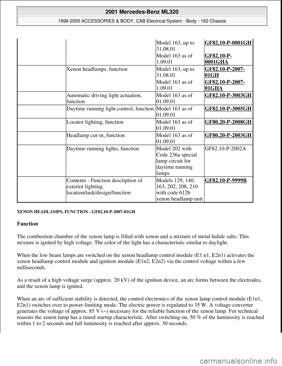
XENON HEADLAMPS, FUNCTION - GF82.10-P-2007-01GH
Function
The combustion chamber of the xenon lamp is filled with xenon and a mixture of metal halide salts. This
mixture is ignited by high voltage. The color of the light has a characteristic similar to daylight.
When the low beam lamps are switched on the xenon headlamp control module (E1 n1, E2n1) activates the
xenon headlamp control module and ignition module (E1n2, E2n2) via the control voltage within a few
milliseconds.
As a result of a high voltage surge (approx. 20 kV) of the ignition device, an arc forms between the electrodes,
and the xenon lamp is ignited.
When an arc of sufficient stability is detected, the control electronics of the xenon lamp control module (E1n1,
E2n1) switches over to power-limiting mode. The electric power is regulated to 35 W. A voltage converter
generates the voltage of approx. 85 V (~) necessary for the reliable function of the xenon lamp. For technical
reasons the xenon lamp has a timed startup characteristic. After switching on, 50 % of the luminosity is reached
within 1 to 2 seconds and full luminosity is reached after approx. 30 seconds.
Model 163, up to
31.08.01GF82.10-P-0001GH
Model 163 as of
1.09.01GF82.10-P-
0001GHA
Xenon headlamps, functionModel 163, up to
31.08.01GF82.10-P-2007-
01GH
Model 163 as of
1.09.01GF82.10-P-2007-
01GHA
Automatic driving light actuation,
functionModel 163 as of
01.09.01GF82.10-P-3003GH
Daytime running light control, functionModel 163 as of
01.09.01GF82.10-P-3005GH
Locator lighting, functionModel 163 as of
01.09.01GF80.20-P-2008GH
Headlamp cut-in, functionModel 163 as of
01.09.01GF80.20-P-2003GH
Daytime running lights, functionModel 202 with
Code 236a special
lamp circuit for
daytime running
lampsGF82.10-P-2002A
Contents - Function description of
exterior lighting,
location/task/design/functionModels 129, 140,
163, 202, 208, 210
with code 612b
xenon headlamp unitGF82.10-P-9999B
2001 Mercedes-Benz ML320
1998-2005 ACCESSORIES & BODY, CAB Electrical System - Body - 163 Chassis
me
Saturday, October 02, 2010 3:30:04 PMPage 20 © 2006 Mitchell Repair Information Company, LLC.
Page 1518 of 4133
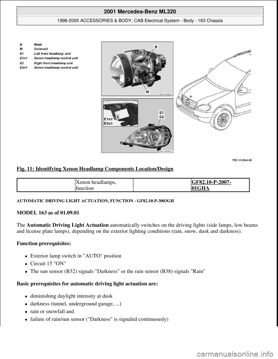
Fig. 11: Identifying Xenon Headlamp Components Location/Design
AUTOMATIC DRIVING LIGHT ACTUATION, FUNCTION - GF82.10-P-3003GH
MODEL 163 as of 01.09.01
The Automatic Driving Light Actuation automatically switches on the driving lights (side lamps, low beams
and license plate lamps), depending on the exterior lighting conditions (rain, snow, dusk and darkness).
Function prerequisites:
Exterior lamp switch in "AUTO" position
Circuit 15 "ON"
The sun sensor (B32) signals "Darkness" or the rain sensor (B38) signals "Rain"
Basic prerequisites for automatic driving light actuation are:
diminishing daylight intensity at dusk
darkness (tunnel, underground garage, ...)
rain or snowfall and
failure of rain/sun sensor ("Darkness" is signaled continuously)
Xenon headlamps,
function GF82.10-P-2007-
01GHA
2001 Mercedes-Benz ML320
1998-2005 ACCESSORIES & BODY, CAB Electrical System - Body - 163 Chassis
me
Saturday, October 02, 2010 3:30:04 PMPage 23 © 2006 Mitchell Repair Information Company, LLC.
Page 1519 of 4133
Fog and other lighting influences, e.g., due to oncoming traffic, do not have any effect on the automatic
driving light actuation.
Automatic driving light actuation when starting a journey and during it
Automatic driving light actuation with driving lights is only possible when the engine is running (circuit
61 ON).
When the engine is switched off and the electronic starter switch is in position "2" (circuit 15 ON) only
the side lamps and the license plate lamps are actuated.
Driving light actuation is disabled as soon as one of the basic prerequisites changes, e.g. when changing
from darkness to daylight after driving through a tunnel.
Automatic driving light actuation at the end of a journey or in darkness
After switching off the engine (circuit 61 OFF) and when the electronic starter switch is in position
"2" (circuit 15 ON), only the side lamps and the license plate lamps remain on.
The exterior lighting is switched off as of key position "1" (circuit 15R).
DAYTIME RUNNING LIGHT ACTUATION, FUNCTION - GF82.10-P-3005GH
MODEL 163 as of 01.09.01
With daytime running lamps the low beam, the side lamps and the license plate lamps are switched on if the
engine is running (there are national variants).
Function prerequisites:
Circuit 61 "ON"
In "AUTO" position of the exterior lamp switch daytime running lamps and automatic driving lights are
OR gated, i.e. depending on the prerequisites daytime running lamps or automatic driving lights are switched
on.
For the daytime running lamp conditions, there is no difference between the positions "0" and "AUTO" of
the exterior lamp switch.
Corresponding to the national legislation, the daytime running lamps can be coded in different variants via
Star Diagnosis.
Canada and USA
Table of contents,
function description for
exterior lighting GF82.10-P-0999A
2001 Mercedes-Benz ML320
1998-2005 ACCESSORIES & BODY, CAB Electrical System - Body - 163 Chassis
me
Saturday, October 02, 2010 3:30:04 PMPage 24 © 2006 Mitchell Repair Information Company, LLC.
Page 1520 of 4133
during the day only the low beam is on
when dark, the side lamps, license plate lamps as well as the switch and controls illumination (circuit
58d) are switched on
With halogen headlights the low beam is operated during the day with a reduced voltage
The lighting switches off automatically if the gearshift lever remains in "P" or "N" position for more than
3 min
Scandinavia
with daytime running lamps the low beam, the side lamps and the license plate lamps are active
the daytime running lamps switch off if the light switch assumes the "side lamps ON" position
Other countries
with daytime running lamps the low beam, the side lamps and the license plate lamps are active
the daytime running lamps are always active
The high beams can only be switched on if the exterior lamp switch:
is at "low beam"
is at "AUTO" and "Darkness" is detected
daytime running lamps for "Other countries" has been coded
CONTENTS - FUNCTION DESCRIPTION OF EXTERIOR LIGHTING, LOCATION/ PURPOSE/DESIGN/FUNCTION -
GF82.10-P-9999B
MODELS 129, 140, 202, 208, 210, 163 up to 31.08.01 with CODE (612b) xenon headlamp unit
MODEL 163 as of 01.09.01 with CODE (614) bi-xenon headlamp unit
Automatic driving light
actuation, function GF82.10-P-3003GH
Table of contents,
function description for
exterior lighting GF82.10-P-0999A
Axle sensor for headlamp range
adjustment, location/taskMODELS 129, 140,
202, 208, 210 with
code 612b xenon
headlamp unitGF82.10-P-2100A
Headlamp range adjustment motor,
location/ taskMODELS 129, 140,
202, 208, 210 with
code 612b xenon
headlamp unitGF82.10-P-2101A
2001 Mercedes-Benz ML320
1998-2005 ACCESSORIES & BODY, CAB Electrical System - Body - 163 Chassis
me
Saturday, October 02, 2010 3:30:04 PMPage 25 © 2006 Mitchell Repair Information Company, LLC.