1997 MERCEDES-BENZ ML500 instrument cluster
[x] Cancel search: instrument clusterPage 2042 of 4133

3. Normalize side power windows. See NORMALIZING POWER WINDOWS .
4. Start engine and run at idle. Turn steering wheel from one lock position to the other to activate steering
angle sensor. Center steering wheel. Message "EI. STAB. PROGRAM GO TO GARAGE" should erase
from multifunction display panel.
5. If equipped, normalize tilting/sliding roof. See NORMALIZING TILTING/SLIDING ROOF
.
6. If equipped, normalize memory power seats, steering column and outside mirror if components are
installed. See NORMALIZING MEMORY POWER SEATS, STEERING COLUMN & OUTSIDE
MIRROR .
Normalizing Power Windows
1. Completely close each window with manual switch. Hold switch in closed position for .3 second.
2. Repeat procedure for each power window.
Normalizing Memory Power Seats, Steering Column & Outside Mirror
1. Using manual switch, move seat to each end position and hold for .3 second. Repeat procedure for each
switch except rear stop of backrest.
2. Repeat procedure for end positions of steering wheel and outside mirrors.
Normalizing Tilting/Sliding Roof
Open roof with SR switch until mechanical stop is reached. Continue to press switch for .5 seconds.
Setting Time
1. Use bottom left button on steering wheel to scroll through menus on instrument cluster to "Settings"
menu.
2. Move selection marker with + or - button to "Time" submenu.
3. Press up or down arrows to "Clock, hours" setting. Confirm selection marker is on the hour setting.
4. Press + or - to set hour. Press reset knob in instrument cluster to confirm.
5. Move selection marker with + or - button to "Time" submenu.
6. Press up or down arrows to "Clock, minutes" setting. Confirm selection marker is on the minutes setting.
7. Press + or - to set minute. Press reset knob in instrument cluster to confirm.
TESTING
If generator malfunctions, check for Diagnostic Trouble Codes (DTCs) in Motor Electronics Sequential Fuel
Injection (ME-SFI) system. See appropriate SELF-DIAGNOSTICS article in ENGINE PERFORMANCE. If
cause of generator malfunction is not engine performance related, replace generator.
RETRIEVING & ERASING DIAGNOSTIC TROUBLE CODES
NOTE: Before replacing any component that scan tool suggests are faulty, ensure that
all wiring connections and harness connectors are okay. Ensure that power and
2001 Mercedes-Benz ML320
2001-04 STARTING & CHARGING SYSTEMS Generators & Regulators - 163 Chassis
me
Saturday, October 02, 2010 3:20:32 PMPage 8 © 2006 Mitchell Repair Information Company, LLC.
Page 2048 of 4133

Fig. 8: Connecting Hand Held Tester Scan Tool To OBD-II Data Link Connector
Courtesy of MERCEDES-BENZ OF NORTH AMERICA.
ON-VEHICLE TESTING
WIRING CONTINUITY
1. Connect voltmeter between generator B+ terminal and ground. Voltmeter should indicate battery voltage.
If battery voltage is not indicated, check battery and check wiring between generator and battery for
corrosion, loose terminals, etc.
2. Turn ignition on and ensure instrument cluster charge indicator light (battery symbol) comes on. If light
does not come on, check wiring between generator and warning light, including indicator bulb.
GENERATOR OUTPUT
1. Ensure connections at battery and generator are clean and tight. Ensure generator, engine and body are
properly grounded. Ensure generator drive belt is properly adjusted and in good condition.
2. Connect load tester/ammeter as per tester manufacturer's instructions. Connect voltmeter leads to battery
terminals. See Fig. 9
. Start engine and run at 2200 RPM for V6 or 2500 RPM for V8. Adjust load tester
to obtain maximum generator output. DO NOT allow voltage to drop to less than 12.7 volts.
3. Maximum generator output should be within a few amps of generator rated output stamped on generator.
If output is not within a few amps of generator rated output, check generator diodes. See DIODE TEST
.
Replace
generator as necessary.
2001 Mercedes-Benz ML320
2001-04 STARTING & CHARGING SYSTEMS Generators & Regulators - 163 Chassis
me
Saturday, October 02, 2010 3:20:32 PMPage 14 © 2006 Mitchell Repair Information Company, LLC.
Page 2066 of 4133

GF54.30-P-2004A
Control buttons, location/task
24.10.96
MODEL
129, 140 as of 1.6.96,
163, 170
The instrument cluster has two control buttons which are on the left
or right next to the speedometer.
The
right control button
is used to adjust the time (refer to Owner's
Manual).
-----------------------------------------------------------------------------------------
The
left control button
is used
D
to regulate the instrument illumination
D
to activate the display illumination
D
to reset the trip odometer display
D
to operate the maintenance display (model 170 only bis 05.97)
D
to operate the Active Service System ASSYST (as of 06.97)
-----------------------------------------------------------------------------------------
n
Purpose/function of terminal 58d, instrument
display illumination
Engines 112, 113, 611 (engines with oil
sensor)
GF54.30-P-3008A
n
Electronic clock
GF54.30-P-3011A
n
Active Service System (ASSYST)
GF00.20-P-0003-01A
Operating instructions, resetting
Model 210 as of 01.03.97 with engines M111,
OM 602, OM 604, OM 605 and
OM 606
As of 06/97 models 129, 140, 170, 202 except
engines 112, 113, 611
(valid for engines with oil level switch)
GF00.20-P-0003-01B
Copyright DaimlerChrysler AG 05.06.2006 CD-Ausgabe G/10/04 . This WIS print-out will not be recorde
d by Modification services.
Page 1
Page 2077 of 4133

GF54.30-P-4103GH
Coolant level switch, location/task/design/function
28.6.99
MODEL
163 as of 1.3.99
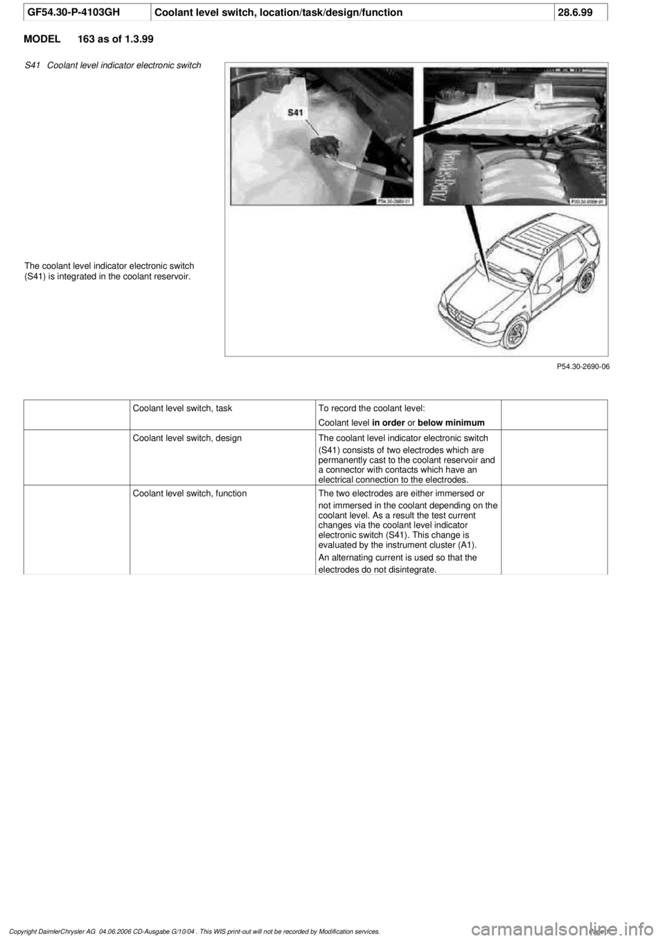
P54.30-2690-06
S41
Coolant level indicator electronic switch
The coolant level indicator electronic switch
(S41) is integrated in the coolant reservoir.
Coolant level switch, taskTo record the coolant level:
Coolant level
in order
or
below minimum
Coolant level switch, design
The coolant level indicator electronic switch
(S41) consists of two electrodes which are
permanently cast to the coolant reservoir and
a connector with contacts which have an
electrical connection to the electrodes.
Coolant level switch, function
The two electrodes are either immersed or
not immersed in the coolant depending on the
coolant level. As a result the test current
changes via the coolant level indicator
electronic switch (S41). This change is
evaluated by the instrument cluster (A1).
An alternating current is used so that the
electrodes do not disintegrate.
Copyright DaimlerChrysler AG 04.06.2006 CD-Ausgabe G/10/04 . This WIS print-out will not be recorde
d by Modification services.
Page 1
Page 2106 of 4133

AD54.30-P-3000-03A
Display instruments/multi-function display
function check IC
Display
instruments
The display instruments must indicate according to operating
conditions.
Phototransistor (models 202, 208, 210)
Point a beam of light at the phototransistor with a pocket lamp, the
display illumination of the LCD displays (outside temperature, trip
odometer, total mileage recorder and electronic clock) must get
brighter.
Instrument cluster with multi-function display
If there are malfunctions (e.g. brake linings worn, coolant level too
low, exterior lamp failure etc.) or system faults (anti-lock brake
system faulty, supplemental restraint system faulty) the warning
display with warning information is inserted in place of outside
temperature, odometer, total mileage recorder and electronic clock.
The warning information is displayed in yellow or red depending on
the fault and a warning tone also sounds.
Copyright DaimlerChrysler AG 05.06.2006 CD-Ausgabe G/10/04 . This WIS print-out will not be recorde
d by Modification services.
Page 1
Page 2107 of 4133

GF54.30-P-3028GH
Displaying coolant level, function
28.6.99
MODEL
163 as of 1.3.99
Function prerequisite
Engine: ON
Function
If the coolant level drops below the minimum mark the low ECL
indicator lamp (A1p11) is illuminated.
To record the coolant level the instrument cluster (A1) is connected
direct to the
coolant level indicator electronic switch (S41)
via two
cables. The
coolant level indicator electronic switch (S41)
consists of two electrodes.
D
If the
level is correct
both electrodes are immersed in the
coolant. The coolant serves as a dielectric between the
electrodes.
D
If the coolant level is below the minimum mark the electrodes of
the sensor are no longer immersed in the coolant. There is only
air between the electrodes as a dielectric. Evaluation
The instrument cluster (A1) sends test pulses to the sensor for
a period of one millisecond. These pulses are deformed
differently depending on the dielectric (air or coolant).
The instrument cluster (A1) evaluates the pulse shape and, if
the coolant level is below the minimum (electrodes are
completely in air), actuates the low ECL indicator lamp (A1p11)
after a delay of
approx. 60 seconds
.
The delay serves to prevent the indicator lamp flickering due to
the coolant moving from side to side on corners or off-road.
Diagnosis
Diagnosis is carried out, as described in the Diagnosis Manual, via
the simulation of the
coolant level indicator electronic switch (S41)
by a resistance.
Coolant level switch,
location/task/design/function
GF54.30-P-4103GH
Copyright DaimlerChrysler AG 04.06.2006 CD-Ausgabe G/10/04 . This WIS print-out will not be recorde
d by Modification services.
Page 1
Page 2108 of 4133

GF00.20-P-2010B
Displaying service, function
25.3.99
MODEL
129 as of 1.8.99
MODEL
163 as of 1.1.00
MODEL
168 as of 1.9.99
MODEL
170 as of 1.12.99
MODEL
202 as of 1.8.99
Display of service to be performed
In addition to the various service displays, the service work to be
performed (A or B) also appears.
The service symbol (wrench) appears once or twice in the display for
this purpose.
The service symbol appears
D
once
for service
A
D
twice
for service B
.
A service A is always followed by a service B.
Following a service B, the next service must be calculated
taking into account the kilometer readings. If the distance of the
current service interval is less than 22 000 km, the next service
is service A, otherwise service B.
This calculation is now performed
automatically
in the
instrument cluster (A1).
The path of the service displayed A or B can be processed in
the service sheet without the need for a calculation.
There is no external difference in the instrument clusters with
and without the service display.
If service A (one service symbol) is displayed, it is then
necessary to ensure by means of the
production date
or the
control unit identifier
, that the vehicle in question is in fact a
vehicle
with service display
. If this is not the case, the service
must be determined as specified in the service sheet.
The table below shows from which control unit identifier the
instrument cluster features the service display:
The control unit identifier can be read with the HHT under menu point
"Control unit version".
Model
Control unit identifier
129
2/04
163
3/04
168
3/20
170
2/23
202
0/20
Displaying remaining service function
GF00.20-P-2007A
Copyright DaimlerChrysler AG 05.06.2006 CD-Ausgabe G/10/04 . This WIS print-out will not be recorde
d by Modification services.
Page 1
Page 2138 of 4133

GF54.21-P-4106GH
Extended activity module position/task
23.6.99
MODEL
163
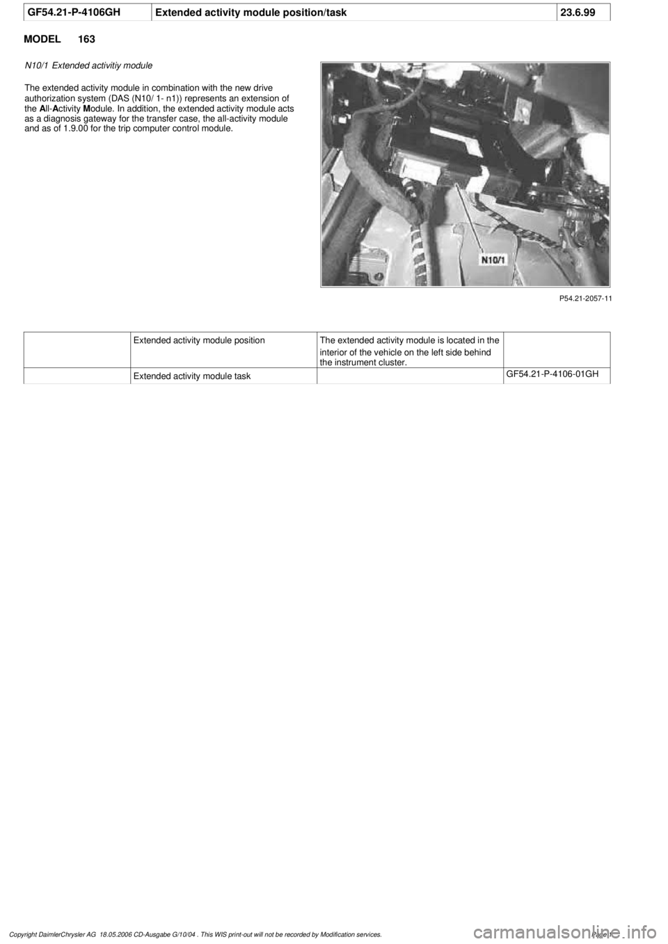
P54.21-2057-11
N10/1
Extended activitiy module
The extended activity module in combination with the new drive
authorization system (DAS (N10/ 1- n1)) represents an extension of
the
A
ll-
A
ctivity
M
odule. In addition, the extended activity module acts
as a diagnosis gateway for the transfer case, the all-activity module
and as of 1.9.00 for the trip computer control module.
Extended activity module position
The extended activity module is located in the
interior of the vehicle on the left side behind
the instrument cluster.
Extended activity module task
GF54.21-P-4106-01GH
Copyright DaimlerChrysler AG 18.05.2006 CD-Ausgabe G/10/04 . This WIS print-out will not be recorde
d by Modification services.
Page 1