1997 MERCEDES-BENZ ML500 instrument cluster
[x] Cancel search: instrument clusterPage 1150 of 4133

GF54.30-P-3010A
Function of acoustic warnings
24.10.96
MODEL
129, 140 as of 1.6.96,
163, 168, 170,
202 as of 1.8.96,
208 up to 31.7.99,
210 as of 1.6.96 up to 30.6.99
Display
Function
Turn signal indicator
ticking
Switching on the turn signal indicator is
indicated acoustically by the turn signal
indicator ticking. The driver's attention is
brought to a defect in the turn signal system
by the turn signal indicator ticking at a higher
frequency.
Turn signal indicator ticking is generated
electromagnetically. The frequency
corresponds to that of the turn signal indicator
lamp.
The signal comes from the combination relay
(turn signal indicator with trailer coupling, rear
window defroster), wiper motor, ATA (N10/2),
on model 210 from the multi-function control
module (N10-1) or from the driver-side signal-
acquisition and actuation module (SAM)
(N10/1), on model 163 from the All-Activity
Module (AAM, N10), on model 168 it is
generated by the integrated turn signal
indicator control in the instrument cluster (A1).
Parking brake reminderThe parking brake warning sounds when
terminal 15g is ON from a speed of approx. 5
km/h.
Piezoelectric loudspeaker (quartz), function
GF54.30-P-3017A
Gear warning, model 168
only with automatic
transmission or automatic
clutch
The acoustic gear warning is active, when
D
a gear is engaged
and
D
the brake is
not
depressed
and
D
the accelerator pedal is
not
pressed
and
D
the driver's door is opened.
These conditions are processed in the gear
recognition module (A61) or in the automatic
clutch control module (N15/4). The
information on the status of the driver's door
is available as a CAN message. It is
transmitted by the instrument cluster (A1).
Piezoelectric loudspeaker (quartz), function
GF54.30-P-3017A
Speed warning
The speed warning sounds when terminal
15g is ON from a speed of approx. 120 km/h.
(on national variants only)
Piezoelectric loudspeaker (quartz), function
GF54.30-P-3017A
Speed limit warning
The warning sounds if the set maximum
speed is exceeded by at least 6 km/h.
(on vehicles with variable cruise control only)
Piezoelectric loudspeaker (quartz), function
GF54.30-P-3017A
Seat belt reminder
On national variants only
Piezoelectric loudspeaker (quartz), function
GF54.30-P-3017A
Switched-on lights
reminder
The switched-on lights reminder sounds when
terminal 15g is OFF, terminal 58k is ON,
when the starter key is removed and the
driver's door is opened.
Piezoelectric loudspeaker (quartz), function
GF54.30-P-3017A
Key reminder
The key reminder when terminal 15g is OFF
and the driver's door is open when the starter
key is inserted
Piezoelectric loudspeaker (quartz), function
GF54.30-P-3017A
Soft top reminder, model
170 only
The soft top reminder sounds when terminal
15 is ON and soft top reminder input is on low
level.
Piezoelectric loudspeaker (quartz), function
GF54.30-P-3017A
Copyright DaimlerChrysler AG 05.06.2006 CD-Ausgabe G/10/04 . This WIS print-out will not be recorde
d by Modification services.
Page 1
Page 1184 of 4133
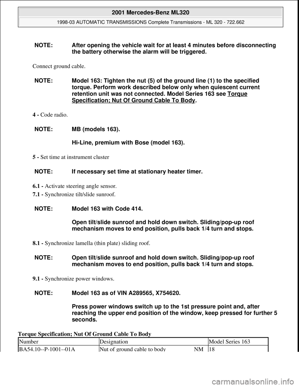
Connect ground cable.
4 - Code radio.
5 - Set time at instrument cluster
6.1 - Activate steering angle sensor.
7.1 - Synchronize tilt/slide sunroof.
8.1 - Synchronize lamella (thin plate) sliding roof.
9.1 - Synchronize power windows.
Torque Specification; Nut Of Ground Cable To Body NOTE: After opening the vehicle wait for at least 4 minutes before disconnecting
the battery otherwise the alarm will be triggered.
NOTE: Model 163: Tighten the nut (5) of the ground line (1) to the specified
torque. Perform work described below only when quiescent current
retention unit was not connected. Model Series 163 see Torque
Specification; Nut Of Ground Cable To Body.
NOTE: MB (models 163).
Hi-Line, premium with Bose (model 163).
NOTE: If necessary set time at stationary heater timer.
NOTE: Model 163 with Code 414.
Open tilt/slide sunroof and hold down switch. Sliding/pop-up roof
mechanism moves to end position, pulls back 1/4 turn and stops.
NOTE: Open tilt/slide sunroof and hold down switch. Sliding/pop-up roof
mechanism moves to end position, pulls back 1/4 turn and stops.
NOTE: Model 163 as of VIN A289565, X754620.
Press power windows switch up to the 1st pressure point and, after
reaching the upper end position of the window, keep pressed for further 5
seconds.
NumberDesignationModel Series 163
BA54.10--P-1001--01ANut of ground cable to bodyNM18
2001 Mercedes-Benz ML320
1998-03 AUTOMATIC TRANSMISSIONS Complete Transmissions - ML 320 - 722.662
me
Saturday, October 02, 2010 3:15:25 PMPage 15 © 2006 Mitchell Repair Information Company, LLC.
Page 1279 of 4133
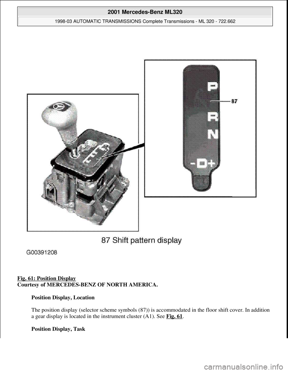
Fig. 61: Position Display
Courtesy of MERCEDES-BENZ OF NORTH AMERICA.
Position Display, Location
The position display (selector scheme symbols (87)) is accommodated in the floor shift cover. In addition
a gear display is located in the instrument cluster (A1). See Fig. 61
.
Position Display, Task
2001 Mercedes-Benz ML320
1998-03 AUTOMATIC TRANSMISSIONS Complete Transmissions - ML 320 - 722.662
me
Saturday, October 02, 2010 3:15:27 PMPage 110 © 2006 Mitchell Repair Information Company, LLC.
Page 1333 of 4133
Task - The ETC control module (N15/3) determines the instantaneous operating condition of the vehicle and
controls all gearshift sequences taking into account the ease of shifting and the driving situation. This involves
receiving, converting and transmitting various digital and analog signals. See Fig. 96
.
It receives operating data in the form of input signals from:
Starter Lock-Out Contact (Y3/6S1)
RPM Sensor 2 (Y3/6N2)
RPM Sensor 3 (Y3/6n3)
Transmission Oil Temperature Sensor (Y3/6B1)
In addition there is a connection via the engine compartment bus to the:
Instrument Cluster (A1)
ME-SFI Control Module (N3/10) or CDI Control Module (N3/9)
The solenoid valves for the modulating and shift pressure and for the gear changes are actuated by the ETC
control module (N15/3).
The pressure required is calculated from all input signals, adjusted to the torque to be transferred. The following
information from other systems is then processed.
ME-SFI Control Module (N3/10) or CDI Control Module (N3/9):
Engine Torque
Engine Speed
Accelerator Pedal Position
Gear Shift
Engine Status
Electronic Selector Lever Module Control Module (N15/5):
Kickdown Switch (S16/6)
Selector Lever Position P/N
Traction System Control Module (N47):
Transmission Ratio
Speeds
Instrument Cluster (A1):
Selector Lever Position/Shift Range
2001 Mercedes-Benz ML320
1998-03 AUTOMATIC TRANSMISSIONS Complete Transmissions - ML 320 - 722.662
me
Saturday, October 02, 2010 3:15:27 PMPage 164 © 2006 Mitchell Repair Information Company, LLC.
Page 1393 of 4133
Location/Task/Design/Function Of Freewheel
See LOCATION/TASK/DESIGN/FUNCTION OF FREEWHEEL
.
Function Of Gear Shift (With Touch Shift)
Transmission with touch shift.
On transmission 722.6 the electrohydraulic control unit converts the electric signals going out from the
electronic transmission control (EGS) into hydraulic signals.
Faults occurring in the ETC control unit (N15/3) are handled by the limp-home system. The limp-home system
is designed so that the driver can reach a Service Operation even under extreme conditions.
Selector lever position "P", "R", "N" and "D" are transmitted by the electronic selector lever module control unit
(N15/5) on the Controller Area Network bus class C (engine compartment) (CAN-C) and in parallel to this by
means of a shift rod to the range selector lever at the transmission end. By touching or holding the selector lever
towards "+" or "-" the shift range is pre-selected and displayed in the instrument cluster (A1) until an upshift of
transmission 722.6 is possible.
Function Of Gear Change
See FUNCTION OF GEAR CHANGE
.
Emergency Default Mode, Function
See LIMP
-HOME MODE, FUNCTION.
Function Of Manual Drive Mode Selection
Oil Level Control, Function
See OIL LEVEL CONTROL, FUNCTION
.
Torque Converter Lockup Clutch Control, Function
See FUNCTION OF TORQUE CONVERTER LOCKUP CLUTCH CONTROL
.
Function Of Gear Shift (Without Touch Shift)
On transmission 722.6 the electrohydraulic control unit converts the electric signals going out from the
electronic transmission control (EGS) into hydraulic signals.
Faults occurring in the ETC control unit (N15/3) are handled by the limp-home system. The limp-home system
is designed so that the driver can reach a Service Operation even under extreme conditions.
Selector lever position "P", "R", "N" and "D" are transmitted by the electronic selector lever module control unit
2001 Mercedes-Benz ML320
1998-03 AUTOMATIC TRANSMISSIONS Complete Transmissions - ML 320 - 722.662
me
Saturday, October 02, 2010 3:15:28 PMPage 224 © 2006 Mitchell Repair Information Company, LLC.
Page 1394 of 4133
(N15/5) on the Controller Area Network bus class C (engine compartment) (CAN-C) and in parallel to this by
means of a shift rod to the range selector lever at the transmission end. By touching or holding the selector lever
towards "+" or "-" the shift range is pre-selected and displayed in the instrument cluster (A1) until an upshift of
transmission 722.6 is possible.
Function Of Gear Change
See FUNCTION OF GEAR CHANGE
.
Emergency Default Mode, Function
See LIMP
-HOME MODE, FUNCTION.
Oil Level Control, Function
See OIL LEVEL CONTROL, FUNCTION
.
Torque Converter Lockup Clutch Control, Function
See FUNCTION OF TORQUE CONVERTER LOCKUP CLUTCH CONTROL
.
Function Of Gear Change
Operation
Every gear change is triggered by the electronic transmission control (ECT). Each shift sequence is assigned a
control block. Each of these contains one overlap regulating valve, one holding pressure shift valve, one shift
pressure shift valve, one common command valve and one electromagnetically actuated switchover valve
(upshift/downshift solenoid valve).
Actuation of the solenoid valve switches over from stationary mode to the shift phase.
When the gear change is complete the solenoid valves are no longer actuated as the different gears are subject to
a self-hold function in stationary mode.
Shifting "N" To "D" (1st Gear), Function
See SHIFTING N TO D (1ST GEAR), FUNCTION
.
Shifting N To D (1st Gear), Function
Transmission 722.6 As Of 1.7.96
2001 Mercedes-Benz ML320
1998-03 AUTOMATIC TRANSMISSIONS Complete Transmissions - ML 320 - 722.662
me
Saturday, October 02, 2010 3:15:28 PMPage 225 © 2006 Mitchell Repair Information Company, LLC.
Page 1442 of 4133
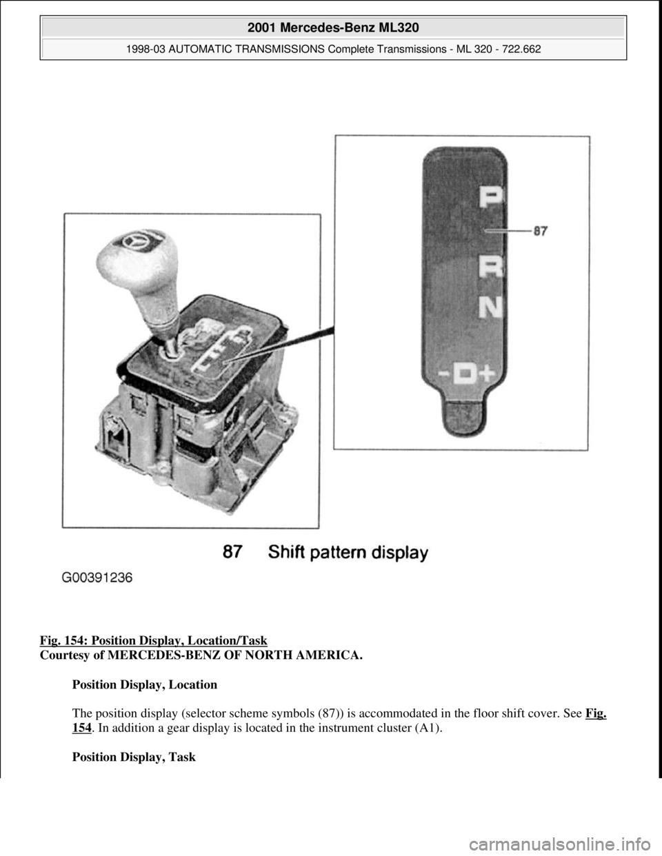
Fig. 154: Position Display, Location/Task
Courtesy of MERCEDES-BENZ OF NORTH AMERICA.
Position Display, Location
The position display (selector scheme symbols (87)) is accommodated in the floor shift cover. See Fig.
154. In addition a gear display is located in the instrument cluster (A1).
Position Display, Task
2001 Mercedes-Benz ML320
1998-03 AUTOMATIC TRANSMISSIONS Complete Transmissions - ML 320 - 722.662
me
Saturday, October 02, 2010 3:15:29 PMPage 273 © 2006 Mitchell Repair Information Company, LLC.
Page 1446 of 4133
Task
The ETC control module (N15/3) determines the instantaneous operating condition of the vehicle and controls
all gearshift sequences taking into account the ease of shifting and the driving situation. This involves receiving,
converting and transmitting various digital and analog signals. See Fig. 157
.
It receives operating data in the form of input signals from:
Starter Lock-Out Contact (Y3/6S1)
RPM Sensor 2 (Y3/6N2)
RPM Sensor 3 (Y3/6N3)
Transmission Oil Temperature Sensor (Y3/6B1)
In addition there is a connection via the engine compartment bus to the:
Instrument Cluster (A1)
ME-SFI Control Module (N3/10) or CDI Control Module (N3/9)
The solenoid valves for the modulating and shift pressure and for the gear changes are actuated by the ETC
control module (N15/3).
The pressure required is calculated from all input signals, adjusted to the torque to be transferred. The following
information from other systems is then processed:
ME-SFI Control Module (N3/10) or CDI Control Module (N3/9):
Engine Torque
Engine Speed
Accelerator Pedal Position
Gear Shift
Engine Status
Electronic selector lever module control module (N15/5):
Kickdown Switch (S16/6)
Selector Lever Position P/N
Traction system control module (N47):
Transmission Ratio
Speeds
Instrument cluster (A1):
2001 Mercedes-Benz ML320
1998-03 AUTOMATIC TRANSMISSIONS Complete Transmissions - ML 320 - 722.662
me
Saturday, October 02, 2010 3:15:29 PMPage 277 © 2006 Mitchell Repair Information Company, LLC.