1997 MERCEDES-BENZ ML500 instrument cluster
[x] Cancel search: instrument clusterPage 2149 of 4133
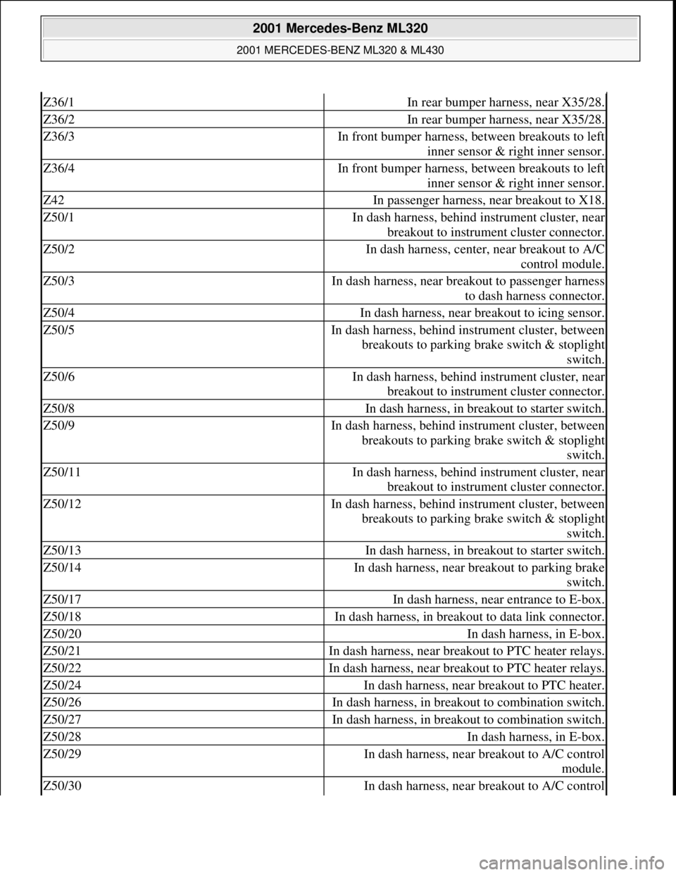
Z36/1In rear bumper harness, near X35/28.
Z36/2In rear bumper harness, near X35/28.
Z36/3In front bumper harness, between breakouts to left
inner sensor & right inner sensor.
Z36/4In front bumper harness, between breakouts to left
inner sensor & right inner sensor.
Z42In passenger harness, near breakout to X18.
Z50/1In dash harness, behind instrument cluster, near
breakout to instrument cluster connector.
Z50/2In dash harness, center, near breakout to A/C
control module.
Z50/3In dash harness, near breakout to passenger harness
to dash harness connector.
Z50/4In dash harness, near breakout to icing sensor.
Z50/5In dash harness, behind instrument cluster, between
breakouts to parking brake switch & stoplight
switch.
Z50/6In dash harness, behind instrument cluster, near
breakout to instrument cluster connector.
Z50/8In dash harness, in breakout to starter switch.
Z50/9In dash harness, behind instrument cluster, between
breakouts to parking brake switch & stoplight
switch.
Z50/11In dash harness, behind instrument cluster, near
breakout to instrument cluster connector.
Z50/12In dash harness, behind instrument cluster, between
breakouts to parking brake switch & stoplight
switch.
Z50/13In dash harness, in breakout to starter switch.
Z50/14In dash harness, near breakout to parking brake
switch.
Z50/17In dash harness, near entrance to E-box.
Z50/18In dash harness, in breakout to data link connector.
Z50/20In dash harness, in E-box.
Z50/21In dash harness, near breakout to PTC heater relays.
Z50/22In dash harness, near breakout to PTC heater relays.
Z50/24In dash harness, near breakout to PTC heater.
Z50/26In dash harness, in breakout to combination switch.
Z50/27In dash harness, in breakout to combination switch.
Z50/28In dash harness, in E-box.
Z50/29In dash harness, near breakout to A/C control
module.
Z50/30In dash harness, near breakout to A/C control
2001 Mercedes-Benz ML320
2001 MERCEDES-BENZ ML320 & ML430
me
Saturday, October 02, 2010 3:21:17 PMPage 9 © 2006 Mitchell Repair Information Company, LLC.
Page 2150 of 4133
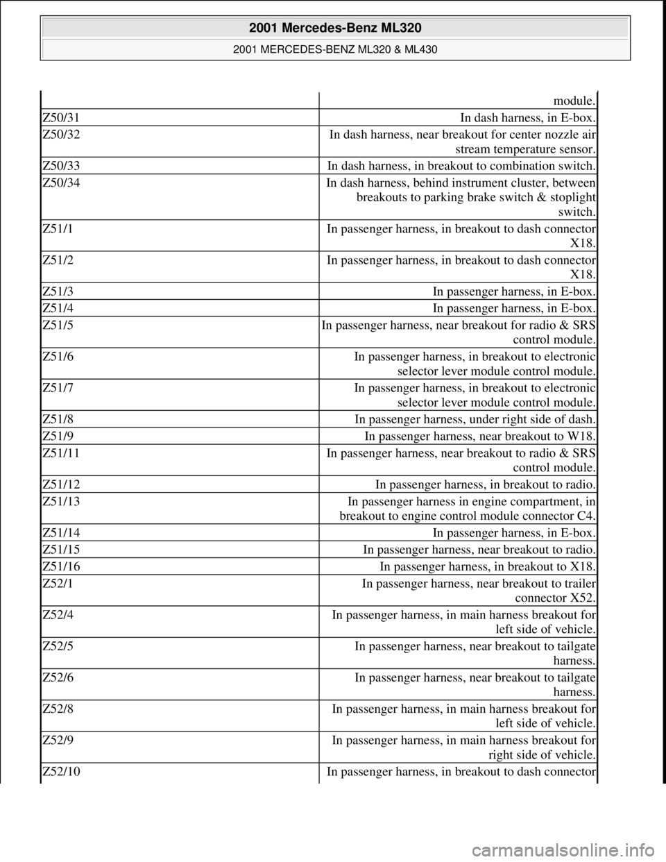
module.
Z50/31In dash harness, in E-box.
Z50/32In dash harness, near breakout for center nozzle air
stream temperature sensor.
Z50/33In dash harness, in breakout to combination switch.
Z50/34In dash harness, behind instrument cluster, between
breakouts to parking brake switch & stoplight
switch.
Z51/1In passenger harness, in breakout to dash connector
X18.
Z51/2In passenger harness, in breakout to dash connector
X18.
Z51/3In passenger harness, in E-box.
Z51/4In passenger harness, in E-box.
Z51/5In passenger harness, near breakout for radio & SRS
control module.
Z51/6In passenger harness, in breakout to electronic
selector lever module control module.
Z51/7In passenger harness, in breakout to electronic
selector lever module control module.
Z51/8In passenger harness, under right side of dash.
Z51/9In passenger harness, near breakout to W18.
Z51/11In passenger harness, near breakout to radio & SRS
control module.
Z51/12In passenger harness, in breakout to radio.
Z51/13In passenger harness in engine compartment, in
breakout to engine control module connector C4.
Z51/14In passenger harness, in E-box.
Z51/15In passenger harness, near breakout to radio.
Z51/16In passenger harness, in breakout to X18.
Z52/1In passenger harness, near breakout to trailer
connector X52.
Z52/4In passenger harness, in main harness breakout for
left side of vehicle.
Z52/5In passenger harness, near breakout to tailgate
harness.
Z52/6In passenger harness, near breakout to tailgate
harness.
Z52/8In passenger harness, in main harness breakout for
left side of vehicle.
Z52/9In passenger harness, in main harness breakout for
right side of vehicle.
Z52/10In passenger harness, in breakout to dash connector
2001 Mercedes-Benz ML320
2001 MERCEDES-BENZ ML320 & ML430
me
Saturday, October 02, 2010 3:21:17 PMPage 10 © 2006 Mitchell Repair Information Company, LLC.
Page 2207 of 4133
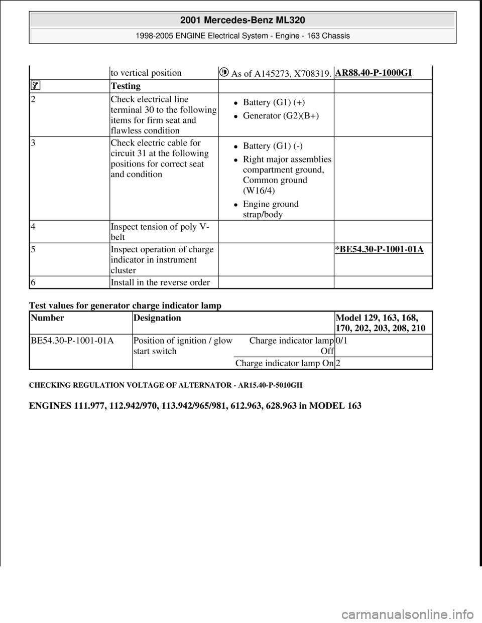
Test values for generator charge indicator lamp
CHECKING REGULATION VOLTAGE OF ALTERNATOR - AR15.40-P-5010GH
ENGINES 111.977, 112.942/970, 113.942/965/981, 612.963, 628.963 in MODEL 163
to vertical position As of A145273, X708319.AR88.40-P-1000GI
Testing
2Check electrical line
terminal 30 to the following
items for firm seat and
flawless conditionBattery (G1) (+)
Generator (G2)(B+)
3Check electric cable for
circuit 31 at the following
positions for correct seat
and conditionBattery (G1) (-)
Right major assemblies
compartment ground,
Common ground
(W16/4)
Engine ground
strap/body
4Inspect tension of poly V-
belt
5Inspect operation of charge
indicator in instrument
cluster *BE54.30-P-1001-01A
6Install in the reverse order
NumberDesignationModel 129, 163, 168,
170, 202, 203, 208, 210
BE54.30-P-1001-01APosition of ignition / glow
start switchCharge indicator lamp
Of
f
0/1
Charge indicator lamp On2
2001 Mercedes-Benz ML320
1998-2005 ENGINE Electrical System - Engine - 163 Chassis
me
Saturday, October 02, 2010 3:18:54 PMPage 53 © 2006 Mitchell Repair Information Company, LLC.
Page 2236 of 4133

GF00.20-P-2009A
Engine oil monitor function
24.10.96
MODEL
129 with ENGINE 112, 113
MODEL
163 with ENGINE 112, 113, 612
MODEL
168 with ENGINE 166, 668
MODEL
202 with ENGINE 112, 611
MODEL
208 up to 31.7.99 with ENGINE 112, 113
MODEL
210 up to 30.6.99 with ENGINE 112, 113, 611
General
The oil level is constantly monitored by the oil sensor, and the
appropriate data transmitted to the processor by the ASSYST.
Oil replenishments are detected automatically and result in a bonus,
which extends the service interval accordingly.
An excess oil level or insufficient oil level appears in the display
together with the oil can symbol.
Display of low oil level at maximum:
D
at driver request
Display of warnings: D
automatically, at the earliest 60 s after engine start and oil
temperature greater than 60°C:
D
if oil level too high: the oil can symbol appears together
with the readout "OIL LEVEL ABOVE MAX". In addition, a
brief warning signal sounds. (On models not fitted with
multifunction displaly, "HI" appears flashing.)
D
if oil level too low: the oil can symbol appears together with
the readout "OIL LEVEL BELOW MIN". In addition, a brief
warning signal sounds. (On models not fitted with multifunction
display, the oil level warning lamp (A1e12) comes on and the
readout "-2L" appears flashing.)
-----------------------------------------------------------------------------------------
D
if oil at minimum: the oil can symbol appears together with
the readout "OIL LEVEL MINIMUM". In addition, a brief
warning signal sounds. (On models not fitted with multifunction
display, the oil level warning lamp (A1e12) comes on.)
D
automatically 13 s after ignition ON:
D
if
no oil
is in engine: the oil can symbol appears together
with the readout "OIL LEVEL BELOW MIN". In addition, a
warning signal sounds. (On models not fitted with multifunction
display, the oil level warning lamp (A1e12) comes on and the
readout "-2L"appears flashing. In addition a brief warning
signal sounds.)
The missing oil quantity displayed no longer changes during the
display. In other words, any change in oil level cannot be observed
directly at the display. The new oil level is only displayed once the
conditions described below exist.
Display of oil quantity at driver request
The text "DISPLAY OIL LEVEL?" appears 10 s after the start switch
has been turned into position "2" (on models not fitted with
multifunction display, the oil can and the clock symbol are displayed).
If the reset button of the trip counter is pressed twice within one sec.
during this readout, for example, "add 1.0L oil" (or "-1.0L")
-----------------------------------------------------------------------------------------
appears in the display if oil level too low. The readout appears only
after the elapse of a waiting time after engine OFF. The waiting time
depends on the engine oil temperature.
It is
D
up to 20°C
30 minutes
D
from 60°C
1 minute
D
The waiting time is between these two limits at other engine oil
temperatures.
Possible readouts are (text in parenthesis relates to models not fitted
with multifunction display.):
D
"OIL LEVEL OKAY" ("o.k."),
D
1.0L, 1.5L, 2L,
D
"Overfilling" ("HI"),
D
"OBSERVE WAITING TIME" (clock symbol flashing and oil can
symbol),
D
"DISPLAY OIL LEVEL" (clock and oil can symbols.)
If there is a fault at the oil sensor (oil level/temperature/quality, B40)
the oil can symbol and the text "OIL LEVEL SENSOR FAULTY"
appears only 30 s after the fault has occurred.
(On models not fitted with multifunction display, the oil level warning
lamp (A1e12) comes on accordingly.)
For diagnosis, read also the injection system control module (N3)
with the HHT. (The instrument cluster (A1) receives the sensor data
through the CAN from the injection system control module (N3)).
-----------------------------------------------------------------------------------------
Oil change
The ASSYST has to be reset each time the oil is changed. Resetting
ASSYST also resets the remaining time and the remaining distance.
Resetting can be performed at the instrument cluster or using the
HHT.
The following data are stored when the system is reset:
D
current kilometer reading rounded off to 100,
D
total oil replenishments in the last interval,
D
remaining distance,
D
remaining time,
D
product of the quality factors,
D
the data of the last 5 resettings in 5 data sets
These data can only be read with the HHT!
If the specified quantity of oil is not replenished when the oil is
changed, the (internal) start distance is reduced.
Detecting oil replenishments
D
With the
HHT
it is possible to retrieve the last 10 oil
replenishments and the corresponding kilometer readings of
the current interval.
D
In the normal case, detection of an oil replenishment is
displayed by the remaining distance in the instrument cluster
being extended
-----------------------------------------------------------------------------------------
Copyright DaimlerChrysler AG 05.06.2006 CD-Ausgabe G/10/04 . This WIS print-out will not be recorde
d by Modification services.
Page 1
Page 2237 of 4133
Oil replenishments are always only detected once the following
conditions are met:
D
the replenished quantity is
at least 1 l
D
after replenishing the oil, the car must be driven a distance of
at
least 5 km
under
normal driving conditions
at an
oil
temperature of at least 60 °C
.
There are instances, however, in which the readout of the remaining
distance nevertheless appears implausible after replenishing oil;
according to the display, no bonus or only a small bonus has been
issued. This is caused by the fact that the remaining distance is
always only displayed within a range from 15 000 km up to 30 000
km (or 20 000 km up to 40 000 km in the case of engine 668), but
internally the system calculates with the actual values which may also
be beyond this range. These internal values can only be displayed
with the HHT.
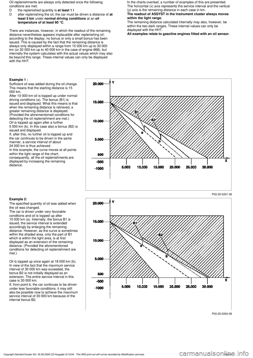
In the charts overleaf, a number of examples of this are presented.
The horizontal (x) axis represents the service interval and the vertical
(y) axis is the remaining distance in each case in km.
The readout of ASSYST in the instrument cluster always moves
within the light range.
The remaining distance calculated internally may also, however, be
within the two dark ranges. These internal values can only be
displayed with the HHT.
All examples relate to gasoline engines fitted with an oil sensor.
P00.20-0201-06
Example 1 :
Sufficient oil was added during the oil change.
This means that the starting distance is 15
000 km.
After 10 000 km oil is topped up under normal
driving conditions (a). The bonus (B1) is
issued and displayed. What this means is that
when the remaining distance is retrieved, a
greater remaining distance is displayed.
(Provided the aforementioned conditions for
detecting the oil replenishment are met.)
Oil is topped up again after a further
5 000 km (b). In this case also a bonus (B2) is
issued and displayed.
If, after this, no further oil is topped up and
the car continues to be driven in the same
manner, a service interval of about
24 000 km is thus achieved.
In this example, the curve moves at all points
within the light range of the chart;
consequently, all the oil replenishments are
displayed by increasing the remaining
distance.
P00.20-0204-06
Example 2:
The specified quantity of oil was added when
the oil was changed.
The car is driven under very favorable
conditions and oil is topped up after
10 000 km (a). Internally, the bonus B1 is
issued, the service interval is extended
accordingly by enlarging the remaining
distance. However, as the curve is sometimes
within the shaded area, only the part of B1
which is within the light area, is at first
displayed as an extension of the remaining
distance. (Provided the aforementioned
conditions for detecting oil replenishment are
met.)
Oil is topped up once again at 18 000 km (b).
In view of the fact that the maximum service
interval of 30 000 km was exceeded, the
bonus B2 is not initially displayed as an
extension. The entire service interval in this
case is 30 000 km.
If, from point b, the car continues to be driven
under less favorable conditions, it may still
also be possible now to achieve the maximum
service interval of 30 000 km because of the
internal bonus B2.
Copyright DaimlerChrysler AG 05.06.2006 CD-Ausgabe G/10/04 . This WIS print-out will not be recorde
d by Modification services.
Page 2
Page 2238 of 4133
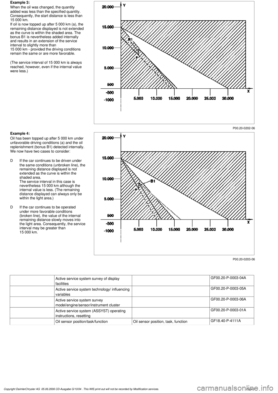
P00.20-0202-06
Example 3:
When the oil was changed, the quantity
added was less than the specified quantity.
Consequently, the start distance is less than
15 000 km.
If oil is now topped up after 5 000 km (a), the
remaining distance displayed is not extended
as the curve is within the shaded area. The
bonus B1 is nevertheless added internally
and results in an extension of the service
interval to slightly more than
15 000 km - provided the driving conditions
remain the same or are more favorable.
(The service interval of 15 000 km is always
reached, however, even if the internal value
were less.)
P00.20-0203-06
Example 4:
Oil has been topped up after 5 000 km under
unfavorable driving conditions (a) and the oil
replenishment (bonus B1) detected internally.
We now have two cases to consider:
D
If the car continues to be driven under
the same conditions (unbroken line), the
remaining distance displayed is not
extended as the curve is within the
shaded area.
The service interval in this case is
nevertheless 15 000 km although the
internal value is less. (The remaining
distance displayed can always only be
within the light area.)
D
If the car continues to be operated
under more favorable conditions
(broken line), the value of the internal
remaining distance slowly moves into
the light area. Consequently, the service
interval may be greater than
15 000 km.
Active service system survey of display
facilities
GF00.20-P-0003-04A
Active service system technology/ influencing
variables
GF00.20-P-0003-05A
Active service system survey
model/engine/sensor/instrument cluster
GF00.20-P-0003-06A
Active service system (ASSYST) operating
instructions, resetting
GF00.20-P-0003-01A
Oil sensor position/task/function
Oil sensor position, task, function
GF18.40-P-4111A
Copyright DaimlerChrysler AG 05.06.2006 CD-Ausgabe G/10/04 . This WIS print-out will not be recorde
d by Modification services.
Page 3
Page 2241 of 4133

AF80.57-P-6406A
Engine sometimes fails to start and fault message "Start Error" appear in the
instrument cluster
13.8.04
MODEL
163.136 /154 /172 #A as of 145273,
163.136 /154 /172 #X as of 708319,
163.113 /128 /157 /174 /175
Operation no. of operation texts or standard texts and flat rates
Category
Op. no.
Operation text
Time
Acc. no.
Code
P
541011
Perform quick test
004 WU
------
P
805030
Replace drive authorization system (DAS [FBS]) control unit
(after check)
006 WU
------
Damage code
Cause
Remedy
82 801 90
When the ignition is switched on (circuit
15), the engine control unit sends a start
enable request to the DAS [FBS] control unit.
If during this request circuit 15 is switched off
or interrupted before the DAS [FBS] control
unit could respond, the variable code sent the
first time is used again the next time circuit 15
is switched on, since the original request is
saved by the DAS [FBS] control.
1
Replace the DAS [FBS] control unit.
AR54.21-P-1300GH
The fault message "Start Error" appears
in instrument cluster.
When ordering a new control unit, please
specify the chassis number.
Parts ordering notes
Part no.
Designation
Quantity
163 545 07 16
FBS control unit
1
Copyright DaimlerChrysler AG 05.06.2006 CD-Ausgabe G/10/04 . This WIS print-out will not be recorde
d by Modification services.
Page 1
Page 2595 of 4133

AF54.30-P-2064A
Fuel gauge not registering correctly after refueling vehicle
4.2.03
MODEL
163.### #A as of 221506 up to 364039,
163.### #X as of 734088 up to 777100
Operation no. of operation texts or standard texts and flat rates
Sector
Op. no.
Operation text
Time
Acc. no.
Code
P
023803
RECODE INSTRUMENT CLUSTER
003 WU/0.3 h
54 208 50
---
Damage Code
Cause
Remedy
Refuel recognition software may not
recognize incremental refueling (< 7 L).
In case of complaint
#
The fuel gauge operation defaults to back-
up mode, and continuously decreases last
stored sensor value based on consumption
data supplied via engine management. This
continues until either refuel recognition or
instrument cluster (A1) reset occurs (via
STAR Diagnosis or power disconnect).
Vehicles with 83 L fuel tank (as of MY2002)
are more susceptible to this condition.
This applies only to instrument clusters
(A1) with diagnostic version 3/05, 3/06,
and 3/07.
1
Connect STAR Diagnosis.
2
Under "Control module adaptations" in
"ICM" menu, set "Fuel tank characteristic
curve" from "Normal" to "Direct sensor
value".
DO NOT replace the instrument cluster
(A1) or fuel pump assembly (M3) for this
condition.
Copyright DaimlerChrysler AG 28.05.2006 CD-Ausgabe G/10/04 . This WIS print-out will not be recorde
d by Modification services.
Page 1