1997 MERCEDES-BENZ ML500 instrument cluster
[x] Cancel search: instrument clusterPage 1485 of 4133
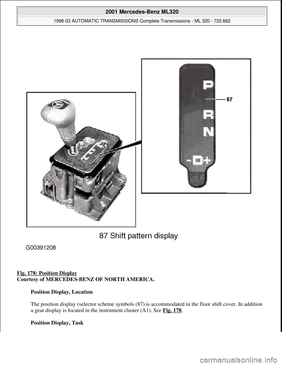
Fig. 178: Position Display
Courtesy of MERCEDES-BENZ OF NORTH AMERICA.
Position Display, Location
The position display (selector scheme symbols (87) is accommodated in the floor shift cover. In addition
a gear display is located in the instrument cluster (A1). See Fig. 178
.
Position Display, Task
2001 Mercedes-Benz ML320
1998-03 AUTOMATIC TRANSMISSIONS Complete Transmissions - ML 320 - 722.662
me
Saturday, October 02, 2010 3:15:30 PMPage 316 © 2006 Mitchell Repair Information Company, LLC.
Page 1569 of 4133
4-channel power amplifier for vehicle loudspeakers
System interlinkage
The radio and navigation unit (A2/56) is provided with the following components for data exchange with
external digital components:
CAN (A1 -A2/56)
The radio and navigation unit (A2/56) is connected with the instrument cluster (A1) via a separate
CAN bus. The difference to the other CAN systems is indicated by the spelling CAN bus (A1-A2/56).
The CAN bus (A1-A2/56) allows the following functions:
Operation of the radio and navigation unit (A2/56)is also possible with the multifunction steering
wheel.
The multifunction display (A1/p13) in the instrument cluster (A1) can display navigation
information on the current operating status of the radio and navigation unit (A2/56) .
The connection to the CAN bus (A1-A2/56) is only realized on models 208 and 210. (Status 3/99)
Digital data bus (D2B)
Data can be exchanged between the external audio components, the telephone system and - if present -
the voice control system over the D2B bus. This allows control data as well as the actual audio signals
(e.g. music from CD changer) to be transferred.
The only additional D2B component presently possible is the CD changer (A2/6) (Status: 3/99)
K bus (diagnostic interface)
Data exchange is accomplished between the diagnostic interface and the hand-held tester (reading out
DTCs and actual values, ...).
The communication between the HHT and all other D2B components is accomplished over the radio
and navigation unit (A2/56) diagnostic interface.
Audio 30 APS, location of
componentsModel 163GF82.61-P-0002-01D
Model 168GF82.61-P-0002-01B
Model 170GF82.61-P-0002-01A
Model 208, model 210&.2.(GF82.61-P-0002-
01C)
Audio 30 APS block
diagramModel 163GF82.61-P-0002-02D
Model 168GF82.61-P-0002-02B
2001 Mercedes-Benz ML320
1998-2005 ACCESSORIES & BODY, CAB Electrical System - Body - 163 Chassis
me
Saturday, October 02, 2010 3:30:05 PMPage 74 © 2006 Mitchell Repair Information Company, LLC.
Page 1676 of 4133
The personal symbols on the map are not updated during active guidance.
Voice control does not react to commands
Occasionally no sound (duration approx. 1 second).
TV screen switches off when standing still
After switching on CD player plays CD1/track 1 instead of title played last
No message when CD magazine sticks during ejection
Wavy interference in navigation display when TV picture is switched off (as if station is not correctly
received)
TCS icons are occasionally not displayed on the map with active dynamic guidance
Telephone book is not activated.
COMAND: A 208 820 40 89, A 210 820 54 89, A 163 820 14 89
Error patterns:
Increased quiescent current.
The personal symbols on the map are not updated during active guidance.
Voice control does not react to commands
No message when CD magazine sticks during ejection
TCS cannot be activated sporadically.
Time in instrument cluster and COMAND differs approx. 1-2 seconds.
COMAND signals CD reading error without any obvious cause
PERFORMING SOFTWARE DOWNLOAD - AF82.85-P-6000-04A
COMAND 2.0-ECE / 2.5-ECE - Perform software download of CD:
Do not start vehicle during download, do not cause other voltage drops in the vehicle electrical system, do
not remove CD and do not switch off unit! (Unit will be damaged!)
In the case of erroneous operation of the download control module, the download starts again or is terminated if
the old software has not been erased previously.
1. Switch off ignition.
2. Remove navigation CD and insert download CD.
3. Switch off control module.
4. After a waiting time of min. 5 s and with buttons * and # pressed simultaneously, switch on unit.
The menu "Service download of CD" appears with menu points "Control module" and "Termination".
5. Select "Start control module" with right knob
2001 Mercedes-Benz ML320
1998-2005 ACCESSORIES & BODY, CAB Electrical System - Body - 163 Chassis
me
Saturday, October 02, 2010 3:30:07 PMPage 181 © 2006 Mitchell Repair Information Company, LLC.
Page 1715 of 4133
(A2/56)
B1010Radio and
navigation unit
(A2/56) switches off
due to undervoltage AD82.61-P-6001-
01A
B1011Radio and
navigation unit
(A2/56) switches off
due to overvoltage AD82.61-P-6001-
01A
B1088Only on model 208,
210:
Malfunction in CAN
connection between
instrument cluster
(A1) and radio and
navigation unit
(A2/56) The radio and navigation unit
(A2/56) is connected to the
instrument cluster (A1)via a separate
CAN bus.
Read out instrument cluster (A1)
DTC memoryCAN line between
A1 and A2/56
B1734Model 163:
Wheel speed signal
from CAN bus
adapter missing
Model 168:
Signal from left rear
wheel speed sensor
(L6/3) missing
Model 170:
Signal from left front
wheel speed sensor
(L6/1) missing
Models 208, 210:
Signal from right
front wheel speed
sensor (L6/2)
missing The wheel speed signals are passed
to the radio and navigation unit
(A2/56) via a separate line and not
directly on CAN.
See also: Chassis Diagnosis Manual,
index 9 or index 10: ?
Index 10.4 ESP (Model 163)
Index 10.3 ESP (Model 168)
Index 10.2 ESP (Model 208, 210)
Index 10.5 ESP (Model 208)AD82.61-P-6001-
03A
AD42.45
-P-1002AZ
AD42.45-P-
1002GCZ
AD42.45-P-1000AZ
See STAR
DIAGNOSIS
B1738Models 168, 208.4:
GPS antenna
(A2/49a2) or lead
defective
Models 170, 208.3:
Rear GPS antenna
(A2/23a2) or lead
defective AD82.61-P-6001-
05A
Model 163:
Telephone and GPS
roof antenna (A2/49)
or telephone and The GPS and telephone radio
signals are transmitted between A2/49
and A2/57 via a common antenna
cable.AD82.61-P-6001-
05B
2001 Mercedes-Benz ML320
1998-2005 ACCESSORIES & BODY, CAB Electrical System - Body - 163 Chassis
me
Saturday, October 02, 2010 3:30:08 PMPage 220 © 2006 Mitchell Repair Information Company, LLC.
Page 1716 of 4133
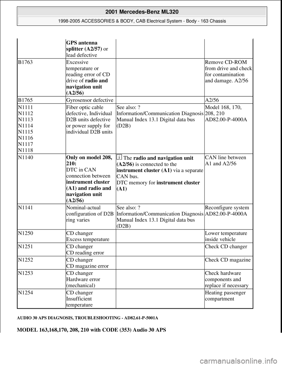
AUDIO 30 APS DIAGNOSIS, TROUBLESHOOTING - AD82.61-P-5001A
MODEL 163,168,170, 208, 210 with CODE (353) Audio 30 APS
GPS antenna
splitter (A2/57) or
lead defective
B1763Excessive
temperature or
reading error of CD
drive of radio and
navigation unit
(A2/56) Remove CD-ROM
from drive and check
for contamination
and damage. A2/56
B1765Gyrosensor defective A2/56
N1111
N1112
N1113
N1114
N1115
N1116
N1117
N1118Fiber optic cable
defective, Individual
D2B units defective
or power supply for
individual D2B unitsSee also: ?
Information/Communication Diagnosis
Manual Index 13.1 Digital data bus
(D2B)Model 168, 170,
208, 210
AD82.00-P-4000A
N1140Only on model 208,
210:
DTC in CAN
connection between
instrument cluster
(A1) and radio and
navigation unit
(A2/56) The radio and navigation unit
(A2/56) is connected to the
instrument cluster (A1)via a separate
CAN bus.
DTC memory for instrument cluster
(A1) CAN line between
A1 and A2/56
N1141Nominal-actual
configuration of D2B
ring variesSee also: ?
Information/Communication Diagnosis
Manual Index 13.1 Digital data bus
(D2B)Reconfigure system
AD82.00-P-4000A
N1250CD changer
Excess temperature Lower temperature
inside vehicle
N1251CD changer
CD reading error Check CD changer
N1252CD changer
CD magazine error Check CD magazine
N1253CD changer
Hardware error
(mechanical) Check hardware
components and
replace if necessary
N1254CD changer
Insufficient
temperature Heating passenger
compartment
2001 Mercedes-Benz ML320
1998-2005 ACCESSORIES & BODY, CAB Electrical System - Body - 163 Chassis
me
Saturday, October 02, 2010 3:30:08 PMPage 221 © 2006 Mitchell Repair Information Company, LLC.
Page 2007 of 4133

AD54.30-P-6000-05GH
CAN input resistance, testing electrical
system of IC
Model 163
t
A
Scope of test
Measuring instrument/
Test connection
Operation/
Requirement
Specified value
D
Possible cause/
Remedy
1.0Instrument cluster (A1)
CAN input resistance
9
v
(B.9)
A1
bK
10
(B.10)
Ignition:
OFF
Coupling "B" (12-pin)
disconnected
approx.
120
WD
A1
Copyright DaimlerChrysler AG 05.06.2006 CD-Ausgabe G/10/04 . This WIS print-out will not be recorde
d by Modification services.
Page 1
Page 2034 of 4133
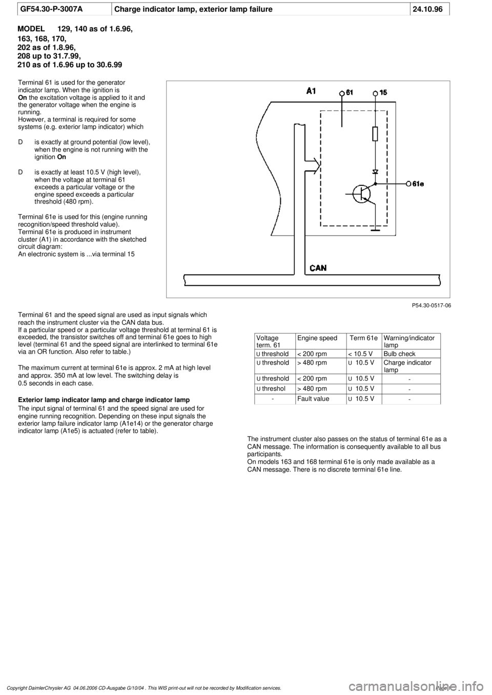
GF54.30-P-3007A
Charge indicator lamp, exterior lamp failure
24.10.96
MODEL
129, 140 as of 1.6.96,
163, 168, 170,
202 as of 1.8.96,
208 up to 31.7.99,
210 as of 1.6.96 up to 30.6.99
P54.30-0517-06
Terminal 61 is used for the generator
indicator lamp. When the ignition is
On
the excitation voltage is applied to it and
the generator voltage when the engine is
running.
However, a terminal is required for some
systems (e.g. exterior lamp indicator) which
D
is exactly at ground potential (low level),
when the engine is not running with the
ignition
On
D
is exactly at least 10.5 V (high level),
when the voltage at terminal 61
exceeds a particular voltage or the
engine speed exceeds a particular
threshold (480 rpm).
Terminal 61e is used for this (engine running
recognition/speed threshold value).
Terminal 61e is produced in instrument
cluster (A1) in accordance with the sketched
circuit diagram:
An electronic system is ...via terminal 15
Terminal 61 and the speed signal are used as input signals which
reach the instrument cluster via the CAN data bus.
If a particular speed or a particular voltage threshold at terminal 61 is
exceeded, the transistor switches off and terminal 61e goes to high
level (terminal 61 and the speed signal are interlinked to terminal 61e
via an OR function. Also refer to table.)
The maximum current at terminal 61e is approx. 2 mA at high level
and approx. 350 mA at low level. The switching delay is
0.5 seconds in each case.
Exterior lamp indicator lamp and charge indicator lamp
The input signal of terminal 61 and the speed signal are used for
engine running recognition. Depending on these input signals the
exterior lamp failure indicator lamp (A1e14) or the generator charge
indicator lamp (A1e5) is actuated (refer to table).
The instrument cluster also passes on the status of terminal 61e as a
CAN message. The information is consequently available to all bus
participants.
On models 163 and 168 terminal 61e is only made available as a
CAN message. There is no discrete terminal 61e line.
Voltage
term. 61
Engine speed
Term 61e
Warning/indicator
lamp
U
threshold
< 200 rpm
< 10.5 V
Bulb check
U
threshold
> 480 rpm
U
10.5 V
Charge indicator
lamp
U
threshold
< 200 rpm
U
10.5 V
-
U
threshol
> 480 rpm
U
10.5 V
-
-
Fault value
U
10.5 V
-
Copyright DaimlerChrysler AG 04.06.2006 CD-Ausgabe G/10/04 . This WIS print-out will not be recorde
d by Modification services.
Page 1
Page 2041 of 4133
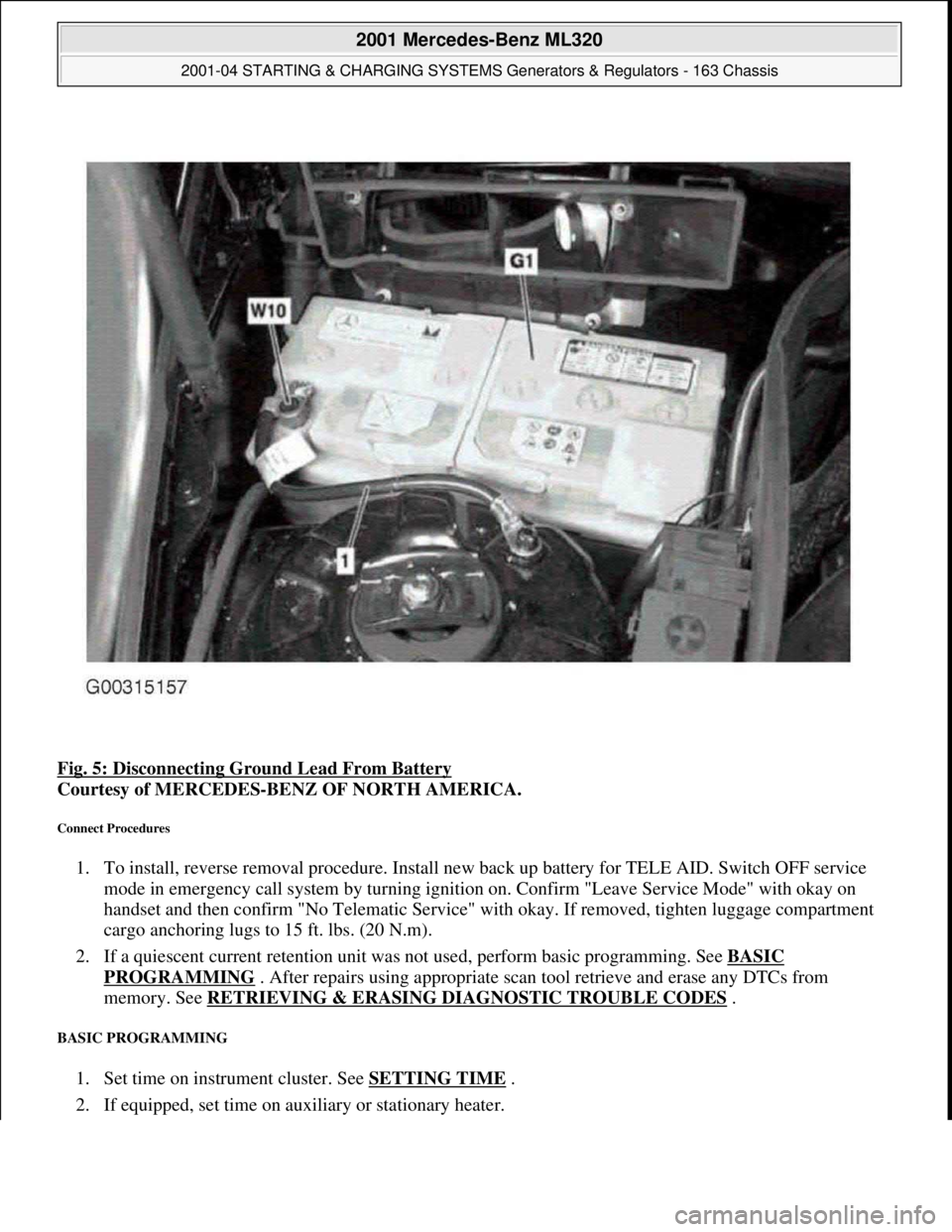
Fig. 5: Disconnecting Ground Lead From Battery
Courtesy of MERCEDES-BENZ OF NORTH AMERICA.
Connect Procedures
1. To install, reverse removal procedure. Install new back up battery for TELE AID. Switch OFF service
mode in emergency call system by turning ignition on. Confirm "Leave Service Mode" with okay on
handset and then confirm "No Telematic Service" with okay. If removed, tighten luggage compartment
cargo anchoring lugs to 15 ft. lbs. (20 N.m).
2. If a quiescent current retention unit was not used, perform basic programming. See BASIC
PROGRAMMING . After repairs using appropriate scan tool retrieve and erase any DTCs from
memory. See RETRIEVING & ERASING DIAGNOSTIC TROUBLE CODES
.
BASIC PROGRAMMING
1. Set time on instrument cluster. See SETTING TIME .
2. If equipped, set time on auxiliary or stationary heater.
2001 Mercedes-Benz ML320
2001-04 STARTING & CHARGING SYSTEMS Generators & Regulators - 163 Chassis
me
Saturday, October 02, 2010 3:20:32 PMPage 7 © 2006 Mitchell Repair Information Company, LLC.