Page 1231 of 4133

Operation
In selector lever position "P" and "N" the starter lockout contact (Y3/6s1) is actuated by a cam track which is
located on the detent plate. See Fig. 29
.
The permanent magnet (47) is moved away from the dry-reed contact (48). The dry-reed contact (48) is opened.
The ETC control module (N15/3) receives an electric signal. The circuit to the starter in the selector lever
position "P" and "N" is closed.
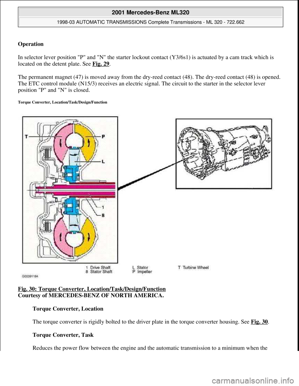
Torque Converter, Location/Task/Design/Function
Fig. 30: Torque Converter, Location/Task/Design/Function
Courtesy of MERCEDES-BENZ OF NORTH AMERICA.
Torque Converter, Location
The torque converter is rigidly bolted to the driver plate in the torque converter housing. See Fig. 30
.
Torque Converter, Task
Reduces the power flow between the en
gine and the automatic transmission to a minimum when the
2001 Mercedes-Benz ML320
1998-03 AUTOMATIC TRANSMISSIONS Complete Transmissions - ML 320 - 722.662
me
Saturday, October 02, 2010 3:15:26 PMPage 62 © 2006 Mitchell Repair Information Company, LLC.
Page 1232 of 4133

vehicle is stationary and the engine is idling, boosts the engine torque and provides infinitely variable
engine speed and torque matching when moving off.
Torque Converter, Design
The impeller (P) is connected to the engine, the turbine wheel (T) is connected to the transmission input
shaft.
The stator (L) is connected to the transmission housing via a freewheel and the stator shaft (8).
Torque Converter, Function
See TORQUE CONVERTER, FUNCTION
.
Torque Converter, Function
Due to the effect of centrifugal force, the blades of the impeller (P) pump the oil outwards to the turbine wheel
(T), causing it to rotate. See Fig. 31
. The turbine wheel blades direct the oil onto the blades of the stator, which
in turn push the oil back to the impeller (P) (arrow). This diversion at the stator (L), which is supported against
the transmission housing via the freewheel, produces and increase in torque. At the maximum speed difference
between the impeller and the turbine wheel (T), the torque conversion achieves its maximum value at a factor of
1.8 to 2.0, dropping to a torque ratio of 1:1 as the speeds converge. From this operating state onwards, also
referred to as the coupling point, the stator (l) rotates with the impeller (P) and the turbine wheel (T).
Efficiencies of up to approximately 98% are achieved in the coupling range.
The oil in the torque converter is constantly being replaced so that the heat produced in the operating phase can
be dissipated via the transmission oil cooler.
2001 Mercedes-Benz ML320
1998-03 AUTOMATIC TRANSMISSIONS Complete Transmissions - ML 320 - 722.662
me
Saturday, October 02, 2010 3:15:26 PMPage 63 © 2006 Mitchell Repair Information Company, LLC.
Page 1234 of 4133
Fig. 31: Torque Converter, Function
Courtesy of MERCEDES-BENZ OF NORTH AMERICA.
Wheel Speed Sensor, Location/Task/Function
2001 Mercedes-Benz ML320
1998-03 AUTOMATIC TRANSMISSIONS Complete Transmissions - ML 320 - 722.662
me
Saturday, October 02, 2010 3:15:26 PMPage 65 © 2006 Mitchell Repair Information Company, LLC.
Page 1244 of 4133
In the front planetary gear set a freewheel (F1, F2) is installed between the front sun gear (V1) and the
stator shaft (8) and in the rear planetary gearset between the rear sun gear (H1) and the intermediate shaft
(3). See Fig. 37
.
Freewheel Task
Optimizes individual gearshifts. Support of the individual elements of a planetary gear set against each
other or against the transmission housing in one direction of rotation in order to permit torque
transmission.
Freewheel Design
The freewheels (F1, F2) consist of an outer race (12), an inner race (13), a number of clamping bodies
(14) and a clamping body cage (15).
Freewheel Function
See FREEWHEEL, FUNCTION
.
Freewheel, Function
2001 Mercedes-Benz ML320
1998-03 AUTOMATIC TRANSMISSIONS Complete Transmissions - ML 320 - 722.662
me
Saturday, October 02, 2010 3:15:26 PMPage 75 © 2006 Mitchell Repair Information Company, LLC.
Page 1247 of 4133
Transmission Housing Breather, Location
The inside of the transmission and the breather (72) are connected by a channel which is cast into the
torque converter casing. See Fig. 39
.
Transmission Housing Breather, Task
The transmission housing vent compensated the pressure in the transmission housing if temperature-
related volume changes in the transmission oil and air occur.
Kick-Down Switch, Location/Task/Design
Fig. 40: Kickdown Switch, Location/Task/Design
Courtesy of MERCEDES-BENZ OF NORTH AMERICA.
Kick-Down Switch, Position
2001 Mercedes-Benz ML320
1998-03 AUTOMATIC TRANSMISSIONS Complete Transmissions - ML 320 - 722.662
me
Saturday, October 02, 2010 3:15:26 PMPage 78 © 2006 Mitchell Repair Information Company, LLC.
Page 1252 of 4133

Courtesy of MERCEDES-BENZ OF NORTH AMERICA.
Multiple-Disc Brake, Location
Three multiple-disc brakes arranged as the front, center and rear multiple-disc brake (B1, B3, B2) are
located in the planetary gear sets in the transmission housing. See Fig. 43
.
Multiple-Disc Brake, Task
Brace the ring gear, sun gear or planet carrier of a planetary gear set against the transmission housing in
order to transmit the drive torque.
Multiple-Disc Brake, Design
A multiple-disc brake consists of a number of internally toothed discs (10) on an internally toothed disc
carrier and externally toothed discs (9) on an externally toothed disc carrier, which is rigidly connected to
the transmission housing.
Multiple-Disc Brake, Function
See MULTIPLE
-DISC BRAKE, FUNCTION.
Multiple-Disc Brake, Function
2001 Mercedes-Benz ML320
1998-03 AUTOMATIC TRANSMISSIONS Complete Transmissions - ML 320 - 722.662
me
Saturday, October 02, 2010 3:15:26 PMPage 83 © 2006 Mitchell Repair Information Company, LLC.
Page 1256 of 4133
Produces a non-positive locking connection between two elements of a planetary gear set or between one
element from each of two planetary gear sets in order to transmit the drive torque.
Multi-Plate Clutch, Design
A multi-plate clutch consists of a number of internally toothed discs (10) on an internally toothed disc
carrier and externally toothed discs (9) on an externally toothed disc carrier.
Multi-Plate Clutch, Function
See MULTI
-PLATE CLUTCH, FUNCTION.
Multi-Plate Clutch, Function
2001 Mercedes-Benz ML320
1998-03 AUTOMATIC TRANSMISSIONS Complete Transmissions - ML 320 - 722.662
me
Saturday, October 02, 2010 3:15:26 PMPage 87 © 2006 Mitchell Repair Information Company, LLC.
Page 1264 of 4133

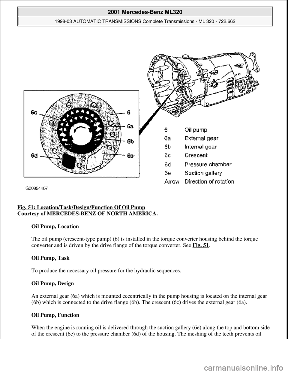
Fig. 51: Location/Task/Desi gn/Function Of Oil Pump
Courtesy of MERCEDES-BENZ OF NORTH AMERICA.
Oil Pump, Location
The oil pump (crescent-type pump) (6) is installed in the torque converter housing behind the torque
converter and is driven by the drive flange of the torque converter. See Fig. 51
.
Oil Pump, Task
To produce the necessary oil pressure for the hydraulic sequences.
Oil Pump, Design
An external gear (6a) which is m ounted eccentrically in the pump housi ng is located on the internal gear
(6b) which is connected to the drive flange (6b). The crescent (6c) drives the external gear (6a).
Oil Pump, Function
When the engine is running oil is delivered through th e suction gallery (6e) along the top and bottom side
of the crescent (6c) to the pr essure chamber (6d) of the housin
g. The meshing of the teeth prevents oil
2001 Mercedes-Benz ML320
1998-03 AUTOMATIC TRANSMI SSIONS Complete Transmissions - ML 320 - 722.662
me
Saturday, October 02, 2010 3:15:26 PMPage 95 © 2006 Mitchell Repair Information Company, LLC.