1997 MERCEDES-BENZ ML430 torque
[x] Cancel search: torquePage 1386 of 4133
Freewheel F1.
Freewheel F2.
Rear multi-disc clutch (K3).
Front Planetary Gear Set
The planet carrier (V3) and sun gear (V1) are rigidly connected to each other via the engaged front multi-disc
clutch (K1). The planetary gearset is therefore blocked and turns as a closed unit at the input speed due to the
mechanical connection of the ring gear (V4) and propeller shaft.
Rear Planetary Gear Set
The center multi-disc clutch (K2) is engaged and transmits the input speed of the input shaft (1) to the planet
carrier (H3) via the hollow gear (M4). The ring gear (H4) turns in the same way as the planet carrier (H3) due to
the mechanical connection with the locked front planetary gearset. This planetary gearset is therefore locked
and turns as a closed unit.
Center Planetary Gear Set
The hollow gear (M4) rotates at input speed due to the engaged center multi-disc clutch (K2). The sun gear
(M1) is supported in the housing via the multi-disc brake (B2). The planet gears (M2) roll over the fixed sun
gear (M1) and provide an increase in torque between the internal gear (M4) and the planet carrier (M3). The
output shaft (5) connected to the planet carrier (M3) turns at a reduced speed in the running direction of the
engine.
Torque Converter, Location/Task/Design/Function
See TORQUE CONVERTER, LOCATION/TASK/DESIGN/FUNCTION
.
Planetary Gear Set, Location/Task/Design/Function
See PLANETARY GEAR SET, LOCATION/TASK/DESIGN/FUNCTION
.
Multiple-Disc Brake, Location/Task/Design/Function
See MULTIPLE
-DISC BRAKE, LOCATION/TASK/DESIGN/FUNCTION.
Multi-Plate Clutch, Location/Task/Design/Function
See MULTI
-PLATE CLUTCH, LOCATION/TASK/DESIGN/FUNCTION.
Power Flow In 4th Gear Function
2001 Mercedes-Benz ML320
1998-03 AUTOMATIC TRANSMISSIONS Complete Transmissions - ML 320 - 722.662
me
Saturday, October 02, 2010 3:15:28 PMPage 217 © 2006 Mitchell Repair Information Company, LLC.
Page 1387 of 4133
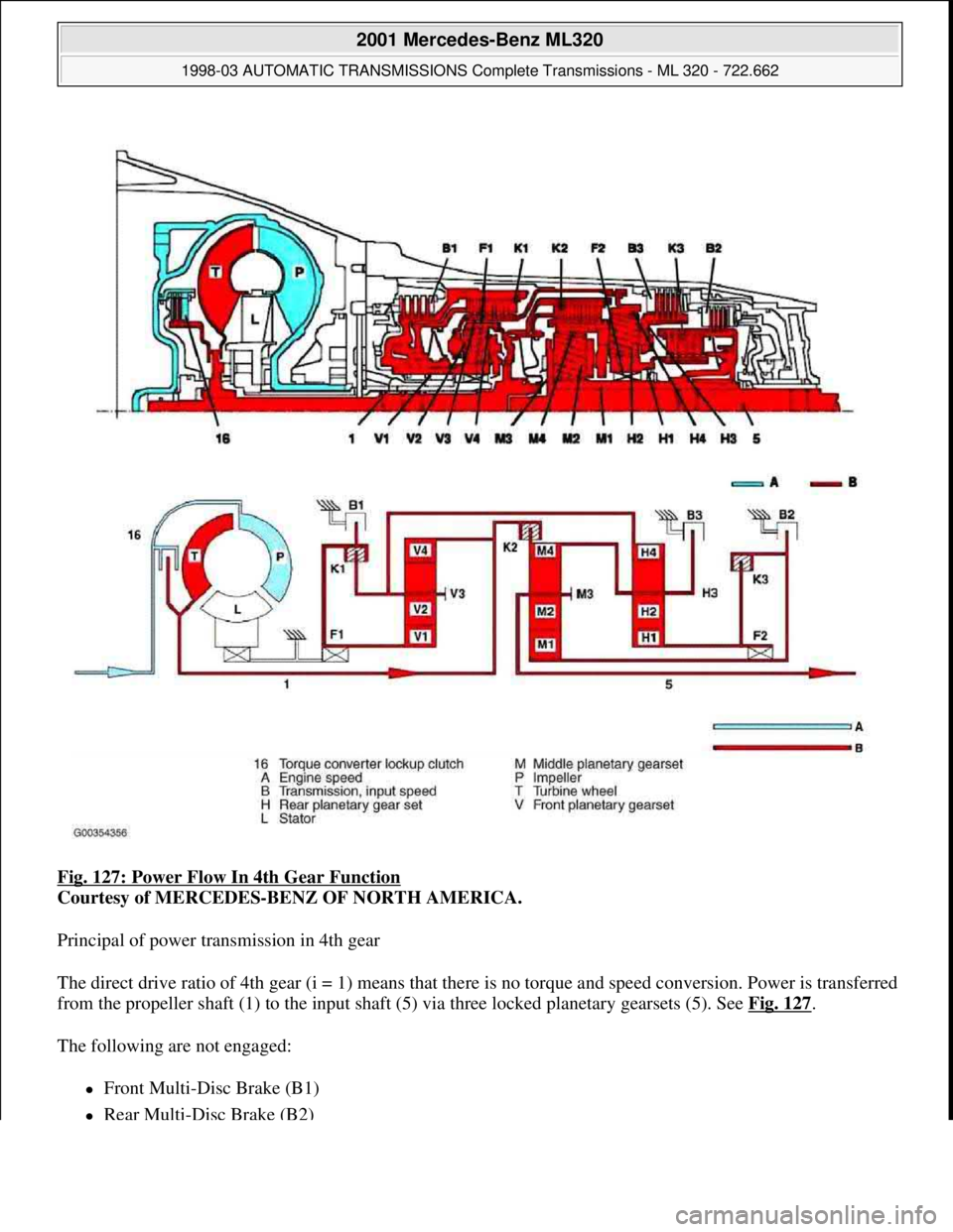
Fig. 127: Power Flow In 4th Gear Function
Courtesy of MERCEDES-BENZ OF NORTH AMERICA.
Principal of power transmission in 4th gear
The direct drive ratio of 4th gear (i = 1) means that there is no torque and speed conversion. Power is transferred
from the propeller shaft (1) to the input shaft (5) via three locked planetary gearsets (5). See Fig. 127
.
The following are not engaged:
Front Multi-Disc Brake (B1)
Rear Multi-Disc Brake (B2)
2001 Mercedes-Benz ML320
1998-03 AUTOMATIC TRANSMISSIONS Complete Transmissions - ML 320 - 722.662
me
Saturday, October 02, 2010 3:15:28 PMPage 218 © 2006 Mitchell Repair Information Company, LLC.
Page 1388 of 4133
Center Multi-Disc Brake (B3)
Freewheel F1
Freewheel F2
Front Planetary Gear Set
The planet carrier (V3) and sun gear (V1) are rigidly connected with each other via the engaged front multi-disc
clutch (K1). The planetary gearset is therefore blocked and turns as a closed unit at the input speed due to the
mechanical connection of the ring gear (V4) and propeller shaft.
Rear Planetary Gear Set
The center multi-disc clutch (K2) is engaged and transmits the input speed of the input shaft (1) to the planet
carrier (H3) via the hollow gear (M4). The ring gear (H4) turns in the same way as the planet carrier (H3) due to
the mechanical connection with the locked front planetary gearset. This planetary gearset is therefore locked
and turns as a closed unit.
Center Planetary Gear Set
The hollow gear (M4) rotates at input speed due to the engaged center multi-disc clutch (K2). The rear multi-
disc clutch (K3) connects the sun gears of the center planetary gear set (M1) and the rear planetary gear set
(H1). The planetary gearset is locked by the same speeds of the ring gear (M4) and the sun gear (M1) and it
turns as a closed unit.
Torque Converter, Location/Task/Design/Function
See TORQUE CONVERTER, LOCATION/TASK/DESIGN/FUNCTION
.
Planetary Gear Set, Location/Task/Design/Function
See PLANETARY GEAR SET, LOCATION/TASK/DESIGN/FUNCTION
.
Multi-Plate Clutch, Location/Task/Design/Function
See MULTI
-PLATE CLUTCH, LOCATION/TASK/DESIGN/FUNCTION.
Power Flow In 5th Gear Function
2001 Mercedes-Benz ML320
1998-03 AUTOMATIC TRANSMISSIONS Complete Transmissions - ML 320 - 722.662
me
Saturday, October 02, 2010 3:15:28 PMPage 219 © 2006 Mitchell Repair Information Company, LLC.
Page 1389 of 4133

Fig. 128: Power Flow In 5th Gear Function
Courtesy of MERCEDES-BENZ OF NORTH AMERICA.
Principles of power transmission in 5th gear
Torque from the torque converter is increased via the propeller shaft (1) and all three planetary gearsets and
transferred to the output shaft (5). See Fig. 128
.
The following are not engaged:
Rear Multi-Disc Brake (B2)
2001 Mercedes-Benz ML320
1998-03 AUTOMATIC TRANSMISSIONS Complete Transmissions - ML 320 - 722.662
me
Saturday, October 02, 2010 3:15:28 PMPage 220 © 2006 Mitchell Repair Information Company, LLC.
Page 1390 of 4133
Center Multi-Disc Brake (B3)
Freewheel F2
Front Multi-Disc Clutch (K1)
Front Planetary Gear Set
The input shaft (1) drives the internal gear (V4). In the drive mode the sun gear (V1) is supported via the locked
freewheel (f1) and in overrun mode in the housing via the engaged front multi-disc brake (B1). The planet gears
(V2) roll over the fixed sun gear (V1) and provide an increase in torque between the internal gear (V4) and the
planet carrier (V3). The planet carrier (V3) moves at reduced speed in the direction of engine rotation.
Rear Planetary Gear Set
The center multi-disc clutch (K2) is engaged and transmits the input speed of the input shaft (1) to the planet
carrier (H3) via the hollow gear (M4). The internal gear (H4) turns at a reduced speed because of its mechanical
connection to the front planet carrier (V3). The planet gears (H2) turn between the ring gear (H4) and the sun
gear (H1). The sun gear (H1) moves at increased speed in the direction of engine rotation.
Center Planetary Gear Set
The hollow gear (M4) rotates at input speed due to the engaged center multi-disc clutch (K2). The rear multi-
disc clutch (K3) transmits a higher speed to the sun gear (M1) due to the connection to the sun gear (H1). The
planet gears (M2) turn between the ring gear (M4) and the sun gear (M1). The speed of the planet carrier (M3)
and the output shaft connected to the planet carrier (5) lies between that of the ring gear (M4) and the sun gear
(M1). This provides a step-up ratio.
Torque Converter, Location/Task/Design/Function
See TORQUE CONVERTER, LOCATION/TASK/DESIGN/FUNCTION
.
Planetary Gear Set, Location/Task/Design/Function
See PLANETARY GEAR SET, LOCATION/TASK/DESIGN/FUNCTION
. .
Multiple-Disc Brake, Location/Task/Design/Function
See MULTIPLE
-DISC BRAKE, LOCATION/TASK/DESIGN/FUNCTION.
Multi-Plate Clutch, Location/Task/Design/Function
See MULTI
-PLATE CLUTCH, LOCATION/TASK/DESIGN/FUNCTION.
Power Flow In Reverse, Function (Without Touch Shift)
2001 Mercedes-Benz ML320
1998-03 AUTOMATIC TRANSMISSIONS Complete Transmissions - ML 320 - 722.662
me
Saturday, October 02, 2010 3:15:28 PMPage 221 © 2006 Mitchell Repair Information Company, LLC.
Page 1392 of 4133
Torque from the torque converter is increased via the propeller shaft (1) and all three planetary gearsets and
transferred with reversed direction of rotation to the output shaft (5). See Fig. 129
.
The following are not engaged:
Rear Multi-Disk Brake (B2)
Freewheel F2
Front Multi-Disk Clutch (K1)
Front Planetary Gear Set.
The input shaft (1) drive the internal gear (V4). In drive mode the sun gear (V1) is supported via the locked
freewheel (F1) and in overrun mode in the housing via the engaged front multi-disk brake (B1). The planet
gears (V2) roll over the fixed sun gear (V1) and provide an increase in torque between the internal gear (V4)
and the planet carrier (V3). The planet carrier (V3) moves at reduced speed in the direction of engine rotation.
Rear Planetary Gear Set.
The planet carrier (H3) is held securely in the housing due to the engaged center multi-disk brake (B3). The
internal gear (H4) turns at a reduced speed because of its mechanical connection to the front planet carrier (V3).
The planet gears (H2) turn between the ring gear (H4) and the sun gear (H1). The direction is reversed due to
the securely held planet carrier (H3) so that the sun gear (H1) rotates in the opposite direction to the engine.
Center Planetary Gear Set.
The hollow gear (M4) is held securely in the housing by the center multi-disk brake (B3) via the mechanical
connection to the planet carrier (H3). The sun gear (M1) rotates backwards due to the engaged rear multi-disk
clutch (K3). The planet gears (M2) roll over the fixed internal gear (M4) and provide an increase in torque
between the sun gear (M1) and the planet carrier (M3). The output shaft (5) connected to the planet carrier (M3)
turns at a reduced speed in the opposite direction to the running direction of the engine.
Torque Converter, Location/Task/Design/Function
See TORQUE CONVERTER, LOCATION/TASK/DESIGN/FUNCTION
.
Planetary Gear Set, Location/Task/Design/Function
See PLANETARY GEAR SET, LOCATION/TASK/DESIGN/FUNCTION
. .
Multiple-Disc Brake, Location/Task/Design/Function
See MULTIPLE
-DISC BRAKE, LOCATION/TASK/DESIGN/FUNCTION.
Multi-Plate Clutch, Location/Task/Design/Function
See MULTI
-PLATE CLUTCH, LOCATION/TASK/DESIGN/FUNCTION.
2001 Mercedes-Benz ML320
1998-03 AUTOMATIC TRANSMISSIONS Complete Transmissions - ML 320 - 722.662
me
Saturday, October 02, 2010 3:15:28 PMPage 223 © 2006 Mitchell Repair Information Company, LLC.
Page 1393 of 4133
Location/Task/Design/Function Of Freewheel
See LOCATION/TASK/DESIGN/FUNCTION OF FREEWHEEL
.
Function Of Gear Shift (With Touch Shift)
Transmission with touch shift.
On transmission 722.6 the electrohydraulic control unit converts the electric signals going out from the
electronic transmission control (EGS) into hydraulic signals.
Faults occurring in the ETC control unit (N15/3) are handled by the limp-home system. The limp-home system
is designed so that the driver can reach a Service Operation even under extreme conditions.
Selector lever position "P", "R", "N" and "D" are transmitted by the electronic selector lever module control unit
(N15/5) on the Controller Area Network bus class C (engine compartment) (CAN-C) and in parallel to this by
means of a shift rod to the range selector lever at the transmission end. By touching or holding the selector lever
towards "+" or "-" the shift range is pre-selected and displayed in the instrument cluster (A1) until an upshift of
transmission 722.6 is possible.
Function Of Gear Change
See FUNCTION OF GEAR CHANGE
.
Emergency Default Mode, Function
See LIMP
-HOME MODE, FUNCTION.
Function Of Manual Drive Mode Selection
Oil Level Control, Function
See OIL LEVEL CONTROL, FUNCTION
.
Torque Converter Lockup Clutch Control, Function
See FUNCTION OF TORQUE CONVERTER LOCKUP CLUTCH CONTROL
.
Function Of Gear Shift (Without Touch Shift)
On transmission 722.6 the electrohydraulic control unit converts the electric signals going out from the
electronic transmission control (EGS) into hydraulic signals.
Faults occurring in the ETC control unit (N15/3) are handled by the limp-home system. The limp-home system
is designed so that the driver can reach a Service Operation even under extreme conditions.
Selector lever position "P", "R", "N" and "D" are transmitted by the electronic selector lever module control unit
2001 Mercedes-Benz ML320
1998-03 AUTOMATIC TRANSMISSIONS Complete Transmissions - ML 320 - 722.662
me
Saturday, October 02, 2010 3:15:28 PMPage 224 © 2006 Mitchell Repair Information Company, LLC.
Page 1394 of 4133
(N15/5) on the Controller Area Network bus class C (engine compartment) (CAN-C) and in parallel to this by
means of a shift rod to the range selector lever at the transmission end. By touching or holding the selector lever
towards "+" or "-" the shift range is pre-selected and displayed in the instrument cluster (A1) until an upshift of
transmission 722.6 is possible.
Function Of Gear Change
See FUNCTION OF GEAR CHANGE
.
Emergency Default Mode, Function
See LIMP
-HOME MODE, FUNCTION.
Oil Level Control, Function
See OIL LEVEL CONTROL, FUNCTION
.
Torque Converter Lockup Clutch Control, Function
See FUNCTION OF TORQUE CONVERTER LOCKUP CLUTCH CONTROL
.
Function Of Gear Change
Operation
Every gear change is triggered by the electronic transmission control (ECT). Each shift sequence is assigned a
control block. Each of these contains one overlap regulating valve, one holding pressure shift valve, one shift
pressure shift valve, one common command valve and one electromagnetically actuated switchover valve
(upshift/downshift solenoid valve).
Actuation of the solenoid valve switches over from stationary mode to the shift phase.
When the gear change is complete the solenoid valves are no longer actuated as the different gears are subject to
a self-hold function in stationary mode.
Shifting "N" To "D" (1st Gear), Function
See SHIFTING N TO D (1ST GEAR), FUNCTION
.
Shifting N To D (1st Gear), Function
Transmission 722.6 As Of 1.7.96
2001 Mercedes-Benz ML320
1998-03 AUTOMATIC TRANSMISSIONS Complete Transmissions - ML 320 - 722.662
me
Saturday, October 02, 2010 3:15:28 PMPage 225 © 2006 Mitchell Repair Information Company, LLC.