1997 MERCEDES-BENZ ML430 torque
[x] Cancel search: torquePage 1310 of 4133
lockup clutch (p-KUB) depending on the control pressure in converter lockup clutch (p-S/KUB). See Fig. 80.
Depending on the working pressure in the converter lockup clutch (p-KUB) the converter lockup clutch (KUB)
is:
Engaged
Disengaged
N slip mode
In the lower position of the converter lockup clutch regulating valve (27) lubricating oil (p-Sm) flows through
the torque converter and oil cooler (65) into the transmission (converter lockup clutch depressurized). In its
regulating position (slipping, torque converter lockup clutch pressurized), a reduced volume of lubricating oil
(p-Sm) flows through the annular passage (27a) bypassing the torque converter and passing direct through the
oil cooler (65) into the transmission. The other part of the lubricating oil (p-Sm) is led via the restrictor (a) into
the torque converter for cooling the converter lockup clutch (KUB).
R/P Lock, Location/Task/Design/Function
2001 Mercedes-Benz ML320
1998-03 AUTOMATIC TRANSMISSIONS Complete Transmissions - ML 320 - 722.662
me
Saturday, October 02, 2010 3:15:27 PMPage 141 © 2006 Mitchell Repair Information Company, LLC.
Page 1333 of 4133
Task - The ETC control module (N15/3) determines the instantaneous operating condition of the vehicle and
controls all gearshift sequences taking into account the ease of shifting and the driving situation. This involves
receiving, converting and transmitting various digital and analog signals. See Fig. 96
.
It receives operating data in the form of input signals from:
Starter Lock-Out Contact (Y3/6S1)
RPM Sensor 2 (Y3/6N2)
RPM Sensor 3 (Y3/6n3)
Transmission Oil Temperature Sensor (Y3/6B1)
In addition there is a connection via the engine compartment bus to the:
Instrument Cluster (A1)
ME-SFI Control Module (N3/10) or CDI Control Module (N3/9)
The solenoid valves for the modulating and shift pressure and for the gear changes are actuated by the ETC
control module (N15/3).
The pressure required is calculated from all input signals, adjusted to the torque to be transferred. The following
information from other systems is then processed.
ME-SFI Control Module (N3/10) or CDI Control Module (N3/9):
Engine Torque
Engine Speed
Accelerator Pedal Position
Gear Shift
Engine Status
Electronic Selector Lever Module Control Module (N15/5):
Kickdown Switch (S16/6)
Selector Lever Position P/N
Traction System Control Module (N47):
Transmission Ratio
Speeds
Instrument Cluster (A1):
Selector Lever Position/Shift Range
2001 Mercedes-Benz ML320
1998-03 AUTOMATIC TRANSMISSIONS Complete Transmissions - ML 320 - 722.662
me
Saturday, October 02, 2010 3:15:27 PMPage 164 © 2006 Mitchell Repair Information Company, LLC.
Page 1335 of 4133
Courtesy of MERCEDES-BENZ OF NORTH AMERICA.
Task - The ETC control module (N15/3) determines the instantaneous operating condition for the vehicle and
controls all gearshift sequences taking into account the ease of shifting and the driving situation. See Fig. 97
.
This involves receiving , converting and transmitting various digital and analog signals.
Input signals:
Starter Lock-Out Contact (Y3/6S1)
RPM Sensor 2 (Y3/6N2)
RPM Sensor 3 (Y3/6N3)
Transmission Oil Temperature Sensor (Y3/6B1)
Kickdown Switch (S16/6)
Gear Recognition Switch (S16/10)
Output signals:
Reverse/parking lock valve
Input and output signals:
Datalink connector (X11/4)
In addition there is a connection via the engine compartment bus to the:
ME-SFI Control Module (N3/10) or CDI Control Module (N3/9)
Traction System Control Module (N47)
Transfer Case Control Module (N78)
The solenoid valves for the modulating and shift pressure and for the gear changes are actuated by the ETC
control module (N15/3). The pressure required is calculated from all input signals, adjusted to the torque to be
transferred.
The following information from other systems is then processed:
ME-SFI Control Module (N3/10) or CDI Control Module (N3/9)
(Y66/1)
Selector lever position P/N to the engine control module (ME-SFI) (N3/10) (only on detection of the
selector lever position "P" or "N" on the transmission range recognition switch (S16/10) and at the starter
interlock contact (Y3/6s1)).
Traction system control module (N47):
Wheel speeds
2001 Mercedes-Benz ML320
1998-03 AUTOMATIC TRANSMISSIONS Complete Transmissions - ML 320 - 722.662
me
Saturday, October 02, 2010 3:15:27 PMPage 166 © 2006 Mitchell Repair Information Company, LLC.
Page 1336 of 4133
Gear shift
Traction status
Transfer case control module (N78):
Position of transfer case (off-road or on-road ratio)
Engine torque
Engine speed
Accelerator pedal position
Gear soft
Engine status
The following information is output to other systems:
ME-SFI Control Module (N3/10) or CDI Control Module (N3/9):
Kickdown switch (S16/6)
Engage drive mode
Traction system control module (N47):
Transmission ratio
Speeds
Electronic Selector Lever Module Control Module, Location/Task/Design (With Touch Shift)
2001 Mercedes-Benz ML320
1998-03 AUTOMATIC TRANSMISSIONS Complete Transmissions - ML 320 - 722.662
me
Saturday, October 02, 2010 3:15:27 PMPage 167 © 2006 Mitchell Repair Information Company, LLC.
Page 1349 of 4133
selected by the driver.
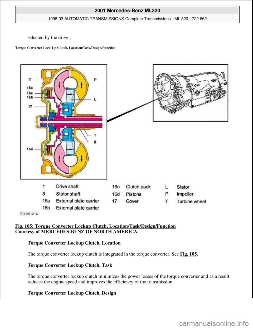
Torque Converter Lock-Up Clutch, Location/Task/Design/Function
Fig. 105: Torque Converter Lockup Clut ch, Location/Task/Design/Function
Courtesy of MERCEDES-BENZ OF NORTH AMERICA.
Torque Converter Lockup Clutch, Location
The torque converter lockup clutch is in tegrated in the torque converter. See Fig. 105
.
Torque Converter Lockup Clutch, Task
The torque converter lockup clutch minimizes the power losses of the torque converter and as a result
reduces the engine speed and improves the efficiency of the transmission.
Torque Converter Lockup Clutch, Design
2001 Mercedes-Benz ML320
1998-03 AUTOMATIC TRANSMI SSIONS Complete Transmissions - ML 320 - 722.662
me
Saturday, October 02, 2010 3:15:28 PMPage 180 © 2006 Mitchell Repair Information Company, LLC.
Page 1350 of 4133
The external plate carrier (16a) is connected to the impeller (P) via the cover shell (17). The internal plate
carrier (16b) is connected to the turbine wheel (T).
Torque Converter Lockup Clutch, Function
See Torque Converter Lockup Clutch, Function
. See TORQUE CONVERTER LOCKUP
CLUTCH, FUNCTION.
Torque Converter Lockup Clutch, Function
2001 Mercedes-Benz ML320
1998-03 AUTOMATIC TRANSMISSIONS Complete Transmissions - ML 320 - 722.662
me
Saturday, October 02, 2010 3:15:28 PMPage 181 © 2006 Mitchell Repair Information Company, LLC.
Page 1352 of 4133
Fig. 106: Torque Converter Lockup Clutch, Function
Courtesy of MERCEDES-BENZ OF NORTH AMERICA.
Operation
When actuated by the ETC control module (N15/3), oil pressure controlled by the torque converter lockup
PWM solenoid Valve (Y3/6y6) is directed through the input shaft (1) to the pressure chamber behind the piston
(16d). See Fig. 106
. The piston presses the clutch pack (16c) together and allows torque to be transferred
directly between the impeller (P) and turbine wheel (T). The torque converter lockup clutch is activated in 5th,
4th and 3rd gears in relation to the engine speed and engine load.
AUTOMATIC TRANSMISSION, FUNCTION
Transmission without touch shift. 722.6 in MODEL 163, 170, 202, 208, 210.
Transmission 722.6 in MODEL 129, 140.
Automatic transmission 722.6 is an electronically controlled 5-speed transmission with a lockup clutch in the
torque converter.
The ratios for the gear stages are achieved by three planetary gear sets. The 5th gear is designed with a step-up
ratio as an overdrive.
Shifting is initiated electronically. The gears are shifted by the corresponding combination of three
hydraulically actuated multi-plate brakes, three hydraulically actuated multi-disc clutches and two mechanical
freewheels.
Basically automatic transmission 722.6 with electronic control offers the following advantages:
Reduced fuel consumption
Improved shift comfort
More favorable gear steps as a result of 5 gears
Enhanced life and reliability
Reduced servicing costs
The electrohydraulic control unit is bolted onto the bottom of the transmission housing. The end of the
transmission is formed by an oil pan made of sheet steel.
The oil pressure for the converter lockup clutch and center multiple disc clutch is supplied via holes in the input
shaft. The oil pressure to the rear multiple-disc clutch is routed through the output shaft. The lubricating oil is
supplied and distributed by additional bore holes in both shafts. All bearing points of the gear sets as well as
freewheels and shift elements are supplied with lubricating oil.
The parking lock gear and drive flange are connected to the output shaft by gearing.
Freewheels F1 and F2 optimize shiftin
g. The front freewheel (F1) rests against the stator shaft extension on the
2001 Mercedes-Benz ML320
1998-03 AUTOMATIC TRANSMISSIONS Complete Transmissions - ML 320 - 722.662
me
Saturday, October 02, 2010 3:15:28 PMPage 183 © 2006 Mitchell Repair Information Company, LLC.
Page 1353 of 4133
transmission side and connects the sun gear of the front planetary gear set to the transmission housing in the
locking direction.
The torque converter housing and transmission housing are made of a metal alloy. They are bolted together and
centered via the outer multiple-disc carrier of the multiple-disc brake B1. A coated intermediate panel seals the
two components.
The oil pump and outer multiple-disc carrier of the front multiple-disc brake are bolted to the converter housing.
The mechanical part consists of the propeller shaft, output shaft, a sun gear shaft and three planetary gearsets
which are coupled together.
In transmissions for powerful engines, the planetary gearsets have 4 planetary gears, while for less powerful
engines the front and rear planetary gear system has three planetary gear wheels. The stator shaft is pressed into
this and is secured against turning by a spline.
The rear freewheel (F2) connects the sun gear of the center planetary gear set to the sun gear of the rear
planetary gearset in the locking direction.
The electrohydraulic control unit consists of the shift plate made of light alloy for hydraulic control and an
electronic control unit.
The electrical control unit consists of a supporting body made of plastic in which the electrical components are
combined. The shell is screwed to the shift plate. Conductor tracks which are integrated into the shell, connect
the electric components to a plug connector. This 13-pin plug connector forms the connection with the vehicle-
side wiring harness and with the ETC 5 (electronic transmission control) control module (N15/5) via a bayonet
lock.
Automatic Transmission, Location Of Mechanical Components
See AUTOMATIC TRANSMISSION, LOCATION OF MECHANICAL PARTS
.
Automatic Transmission, Location Of Electrical/Electronic Components
See AUTOMATIC TRANSMISSION, LOCATION OF ELECTRIC/ELECTRONIC
COMPONENTS.
Automatic Transmission, Location Of Hydraulic Components
See AUTOMATIC TRANSMISSION, POSITION OF HYDRAULIC COMPONENTS
.
Automatic Transmission, Location of Components, Floor Shift
See AUTOMATIC TRANSMISSION, LOCATION OF COMPONENTS, FLOOR SHIFT
.
Automatic Transmission, Selector Lever Positions
2001 Mercedes-Benz ML320
1998-03 AUTOMATIC TRANSMISSIONS Complete Transmissions - ML 320 - 722.662
me
Saturday, October 02, 2010 3:15:28 PMPage 184 © 2006 Mitchell Repair Information Company, LLC.