Page 3936 of 4133
Rear axle torsion bar
Parts ordering notes
2Install pinch nut (2) on top of previously torqued connecting rod bolt nut
3Counterhold connecting rod bolt nut (1) while torquing pinch nut (2)*BA32.20-P-1003-04F
4Repeat for opposite side
NumberDesignationModel 163
BA32.20-P-1001-04FNut, connecting rod to
torsion barNM28
BA32.20-P-1003-04FPinch nut, connecting rod
to torsion barNM28
Part no.DesignationQuantity
N910123 008001Pinch Nut1 per side
2001 Mercedes-Benz ML320
1998-2005 SUSPENSION Suspension - 163 Chassis
me
Saturday, October 02, 2010 3:37:36 PMPage 28 © 2006 Mitchell Repair Information Company, LLC.
Page 3941 of 4133
AR46.40-P-0200-02C
Pressing out and attaching track rod joint at
steering knuckle
k
Surface protection on track rod screw
connection to steering knuckle modified
BT46.40-P-0001-01A
Modification notes
24.3.99
Surface protection on track rod screw connection to
steering knuckle modified
Model 210
BT46.40-P-0001-01A
New tightening torques incorporated
*BA46.40-P-1002-01A
Track rod
Number
Designation
Model 210
BA46.40-P-1002-01A
Self-locking nut, track rod to steering
knuckle
yellow
Nm
60
silver or blue
Nm
70
Track rod
Number
Designation
Model 163
BA46.40-P-1001-01C
Self-locking nut, track rod to steering knuckle
Nm
55
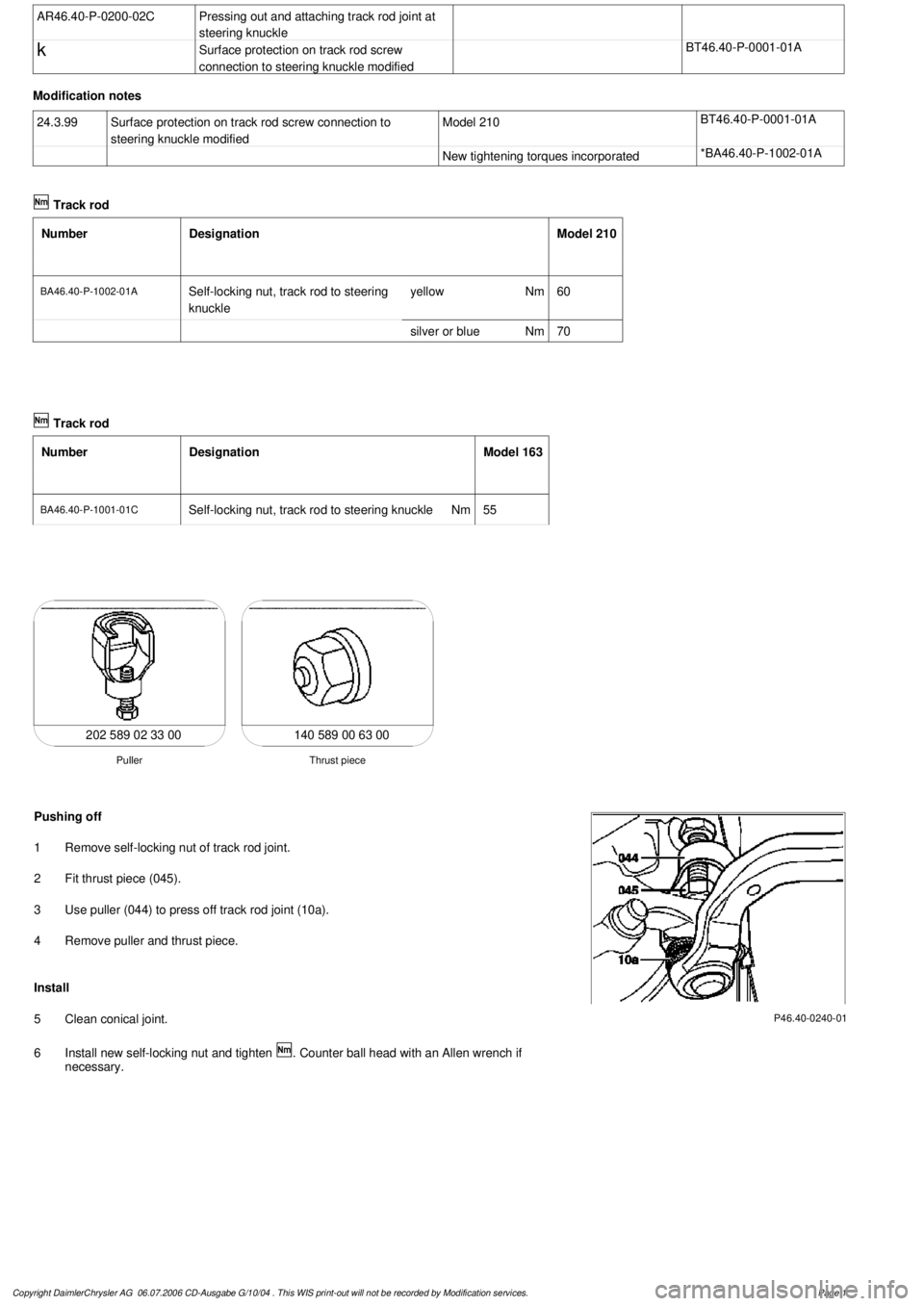
140 589 00 63 00
Thrust piece
Puller
202 589 02 33 00
P46.40-0240-01
Pushing off
1
Remove self-locking nut of track rod joint.
2
Fit thrust piece (045).
3
Use puller (044) to press off track rod joint (10a).
4
Remove puller and thrust piece.
Install
5
Clean conical joint.
6
Install new self-locking nut and tighten
. Counter ball head with an Allen wrench if
necessary.
Copyright DaimlerChrysler AG 06.07.2006 CD-Ausgabe G/10/04 . This WIS print-out will not be recorde
d by Modification services.
Page 1
Page 3949 of 4133
AR01.20-P-5014-02A
Remove/install cylinder head cover trim
Crankcase ventilation, cylinder head cover
Number
Designation
Engine
611.960/
961/962
BA01.20-P-1002-01A
Screw of trim panel of cylinder head cover
to cylinder head cover
Nm
10
BA01.20-P-1003-01A
Screw attaching cover panel to charge air
distribution pipe
Nm
10
Crankcase ventilation, cylinder head cover
Number
Designation
Engine
646.951/961,
647
Engine
646.962/963
BA01.20-P-1002-01G
Bolt, trim panel of cylinder
head cover to cylinder head
Nm
99
BA01.20-P-1003-01G
Bolt, cover to charge air
distribution pipe.
Nm
99
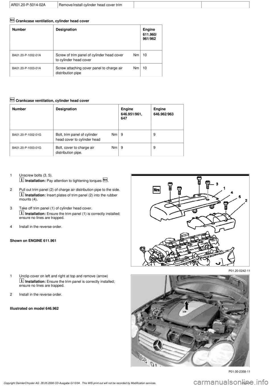
P01.20-0242-11
1
Unscrew bolts (3, 5).
Installation:
Pay attention to tightening torques
.
2
Pull out trim panel (2) of charge air distribution pipe to the side.
Installation:
Insert plates of trim panel (2) into the rubber
mounts (4)
.
3
Take off trim panel (1) of cylinder head cover.
Installation:
Ensure the trim panel (1) is correctly installed;
ensure no lines are trapped.
4
Install in the reverse order.
Shown on ENGINE 611.961
P01.00-2358-11
1
Unclip cover on left and right at top and remove (arrow)
Installation:
Ensure the trim panel is correctly installed;
ensure no lines are trapped.
2
Install in the reverse order.
Illustrated on model 646.962
Copyright DaimlerChrysler AG 28.05.2006 CD-Ausgabe G/10/04 . This WIS print-out will not be recorde
d by Modification services.
Page 1
Page 3950 of 4133
AR01.20-P-5014-02B
Remove/install cylinder head cover trim
Crankcase ventilation, cylinder head cover
Number
Designation
Engine
612.961/
962/967
Engine
612.963
Engine
612.965/
966
Engine
612.990
BA01.20-P-1002-01A
Screw of trim panel of cylinder head cover
to cylinder head cover
NM
101010
8
BA01.20-P-1003-01A
Screw attaching cover panel to charge air
distribution pipe
NM
101010
-
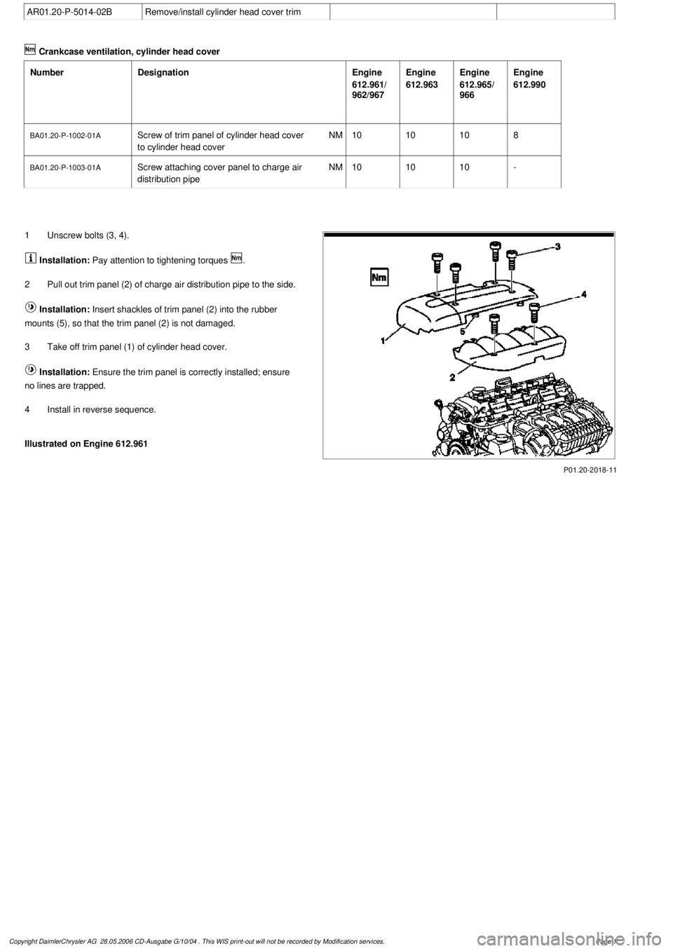
P01.20-2018-11
1
Unscrew bolts (3, 4).
Installation:
Pay attention to tightening torques
.
2
Pull out trim panel (2) of charge air distribution pipe to the side.
Installation:
Insert shackles of trim panel (2) into the rubber
mounts (5), so that the trim panel (2) is not damaged.
3
Take off trim panel (1) of cylinder head cover.
Installation:
Ensure the trim panel is correctly installed; ensure
no lines are trapped.
4
Install in reverse sequence.
Illustrated on Engine 612.961
Copyright DaimlerChrysler AG 28.05.2006 CD-Ausgabe G/10/04 . This WIS print-out will not be recorde
d by Modification services.
Page 1
Page 3951 of 4133
AR01.20-P-5014-02C
Remove/install cylinder head cover trim
Crankcase ventilation, cylinder head cover
Number
Designation
Engine
613.960/
961
BA01.20-P-1002-01A
Screw of trim panel of cylinder head cover
to cylinder head cover
Nm
10
BA01.20-P-1003-01A
Screw attaching cover panel to charge air
distribution pipe
Nm
10
Crankcase ventilation, cylinder head cover
Number
Designation
Engine
648
BA01.20-P-1002-01G
Bolt, trim panel of cylinder
head cover to cylinder head
Nm
9
BA01.20-P-1003-01G
Bolt, cover charge air
distribution pipe
Nm
9
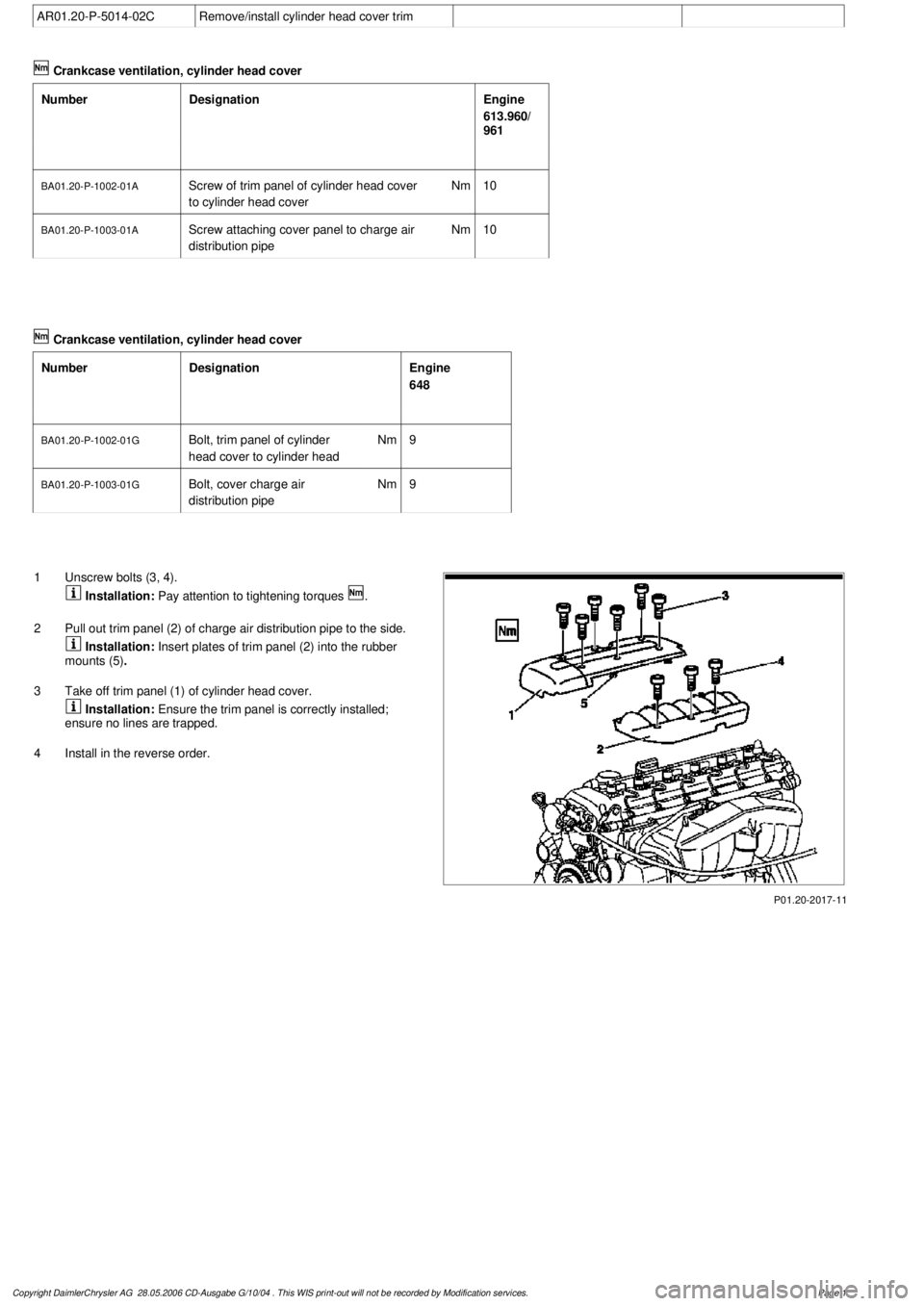
P01.20-2017-11
1
Unscrew bolts (3, 4).
Installation:
Pay attention to tightening torques
.
2
Pull out trim panel (2) of charge air distribution pipe to the side.
Installation:
Insert plates of trim panel (2) into the rubber
mounts (5)
.
3
Take off trim panel (1) of cylinder head cover.
Installation:
Ensure the trim panel is correctly installed;
ensure no lines are trapped.
4
Install in the reverse order.
Copyright DaimlerChrysler AG 28.05.2006 CD-Ausgabe G/10/04 . This WIS print-out will not be recorde
d by Modification services.
Page 1
Page 3986 of 4133
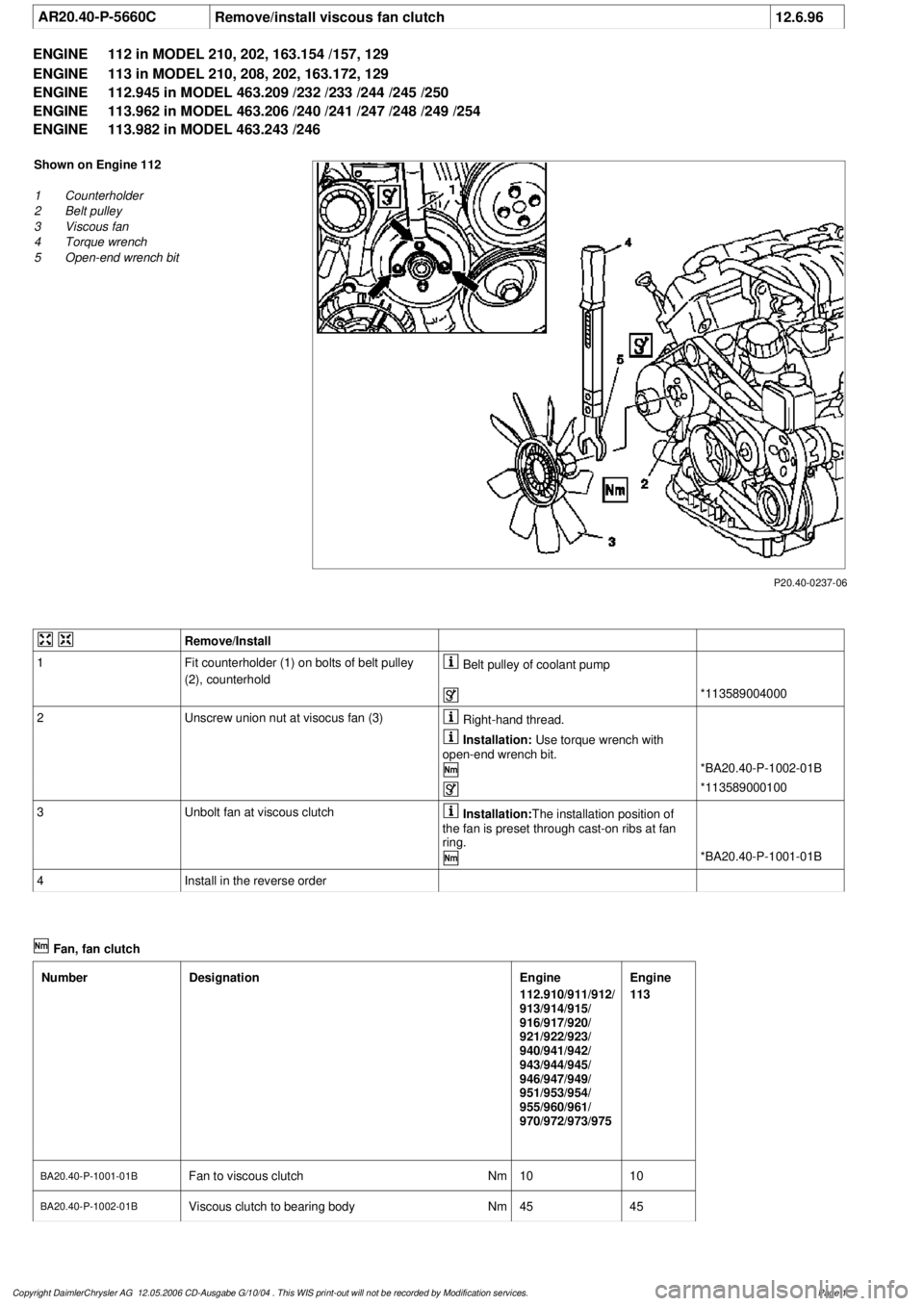
AR20.40-P-5660C
Remove/install viscous fan clutch
12.6.96
ENGINE
112 in MODEL 210, 202, 163.154 /157, 129
ENGINE
113 in MODEL 210, 208, 202, 163.172, 129
ENGINE
112.945 in MODEL 463.209 /232 /233 /244 /245 /250
ENGINE
113.962 in MODEL 463.206 /240 /241 /247 /248 /249 /254
ENGINE
113.982 in MODEL 463.243 /246
P20.40-0237-06
Shown on Engine 112
1
Counterholder
2
Belt pulley
3
Viscous fan
4
Torque wrench
5
Open-end wrench bit
Remove/Install
1
Fit counterholder (1) on bolts of belt pulley
(2), counterhold
Belt pulley of coolant pump
*113589004000
2
Unscrew union nut at visocus fan (3)
Right-hand thread.
Installation:
Use torque wrench with
open-end wrench bit.
*BA20.40-P-1002-01B
*113589000100
3
Unbolt fan at viscous clutch
Installation:
The installation position of
the fan is preset through cast-on ribs at fan
ring.
*BA20.40-P-1001-01B
4
Install in the reverse order
Fan, fan clutch
Number
Designation
Engine
112.910/911/912/
913/914/915/
916/917/920/
921/922/923/
940/941/942/
943/944/945/
946/947/949/
951/953/954/
955/960/961/
970/972/973/975
Engine
113
BA20.40-P-1001-01B
Fan to viscous clutch
Nm
1010
BA20.40-P-1002-01B
Viscous clutch to bearing body
Nm
4545
Copyright DaimlerChrysler AG 12.05.2006 CD-Ausgabe G/10/04 . This WIS print-out will not be recorde
d by Modification services.
Page 1
Page 3995 of 4133
BA40.10-P-1001-01A
Wheel bolt
Nm
150150
126 589 04 09 00
Wrench socket
Commercially available tools
(see Workshop Equipment Manual)
Number
Designation
Make (e. g.)
Order number
WH58.30-Z-1002-10A
Electric or compressed air impact wrench with limited tightening torque,
see
D
trial reports on test benches and tools for
Mercedes Benz workshops, Volume 2, 40.1
D
Workshop Equipment Manual Volume 1 "G" Group 40
651004700
6510053001
Copyright DaimlerChrysler AG 06.07.2006 CD-Ausgabe G/10/04 . This WIS print-out will not be recorde
d by Modification services.
Page 2