1997 MERCEDES-BENZ ML430 torque
[x] Cancel search: torquePage 3233 of 4133
6. Remove A-pillar panel trim. Remove instrument cluster. Remove defroster vent cover. Remove air vents
and side air nozzles. With assistance, remove upper instrument panel.
7. Remove passenger-side air bag. Remove right side lower instrument panel cover. Remove instrument
panel carrier screws from A/C housing unit. Remove left side lower instrument panel cover.
8. Remove insulating mat between steering column and instrument panel carrier. Remove steering column
bolts and nuts from instrument panel carrier. See Fig. 8
. Remove instrument panel carrier center tunnel
bolts. Disconnect steering column connectors.
9. Remove wiring harness from instrument panel carrier. Remove wiper washer system. Remove instrument
panel carrier nuts from engine compartment side of firewall.
10. Remove A-pillar bolt covers and remove instrument panel carrier A-pillar bolts. With assistance, remove
instrument panel carrier through passenger door. To install, reverse removal procedure.
11. Ensure instrument panel bottom section guide tongues "B" are seated into instrument panel upper section
mounts. See Fig. 8
. Tighten nuts and bolts to specification. See TORQUE SPECIFICATIONS .
Recode radio. See RECODING RADIO
under PROGRAMMING.
Fig. 7: Removing Instrument Panel Bottom Section
Courtesy of MERCEDES-BENZ OF NORTH AMERICA.
2001 Mercedes-Benz ML320
2000-01 MANUAL A/C-HEATER SYSTEMS ML 320, ML 430 & ML 55
me
Saturday, October 02, 2010 3:25:10 PMPage 22 © 2006 Mitchell Repair Information Company, LLC.
Page 3236 of 4133
Fig. 9: Replacing Intake Air Dust Filter
Courtesy of MERCEDES-BENZ OF NORTH AMERICA.
RECEIVER-DRIER
Removal & Installation
1. Discharge A/C system, using approved refrigerant recovery/recycling equipment. Remove headlight
units. Remove headlight units. Remove upper frame crossmember, release hood release control cable and
remove crossmember. See Fig. 6
.
2. Remove bolts from receiver-drier refrigerant lines. See Fig. 5
. Disconnect refrigerant lines from receiver-
drier. Plug exposed openings to protect A/C system from debris and moisture. Discard "O" rings. Loosen
receiver-drier clamp bolt. Remove receiver-drier. To install, reverse removal procedure.
3. When installing a new receiver-drier, add 0.34 ounce of NEW refrigerant oil to receiver-drier. Use NEW
"O" rings. Tighten refrigerant line bolts to specification. See TORQUE SPECIFICATIONS
.
TORQUE SPECIFICATIONS
TORQUE SPECIFICATIONS
WIRING DIAGRAMS
ApplicationFt. Lbs. (N.m)
Compressor Mounting Bolts15 (20)
Refrigerant Line-To-Compressor Bolt15 (20)
Refrigerant Line-To-Condenser Bolt15 (20)
Steering Column Bolt15 (20)
Steering Column Nut13 (18)
INCH Lbs. (N.m)
Expansion Valve Self-Locking Nut89 (10)
Refrigerant Line-To-Receiver-Drier Bolt89 (10)
2001 Mercedes-Benz ML320
2000-01 MANUAL A/C-HEATER SYSTEMS ML 320, ML 430 & ML 55
me
Saturday, October 02, 2010 3:25:10 PMPage 25 © 2006 Mitchell Repair Information Company, LLC.
Page 3340 of 4133
AC OFF BUTTON, FUNCTION - GF83.40-P-2107-01GI
Function
When the AC OFF button ( ) on the automatic air conditioning push-button control module is pressed an
LED comes on, the refrigerant compressor is switched off and cooling therefore switched off The air is no
longer cooled and dried.
Vehicles with diesel engine:
Additionally the electric heater booster is switched off. All other functions are retained.
In order to switch off the refrigerant compressor the push-button control module sends a switch-off request over
the CAN. At the same time, the compressor torque value is set to "0". After a specified time delay the
refrigerant compressor is switched off.
AC OFF BUTTON, LOCATION/TASK/FUNCTION - GF83.40-P-2107GI
MODEL 163 as of 1.9.01 with CODE (580a) Automatic air conditioning
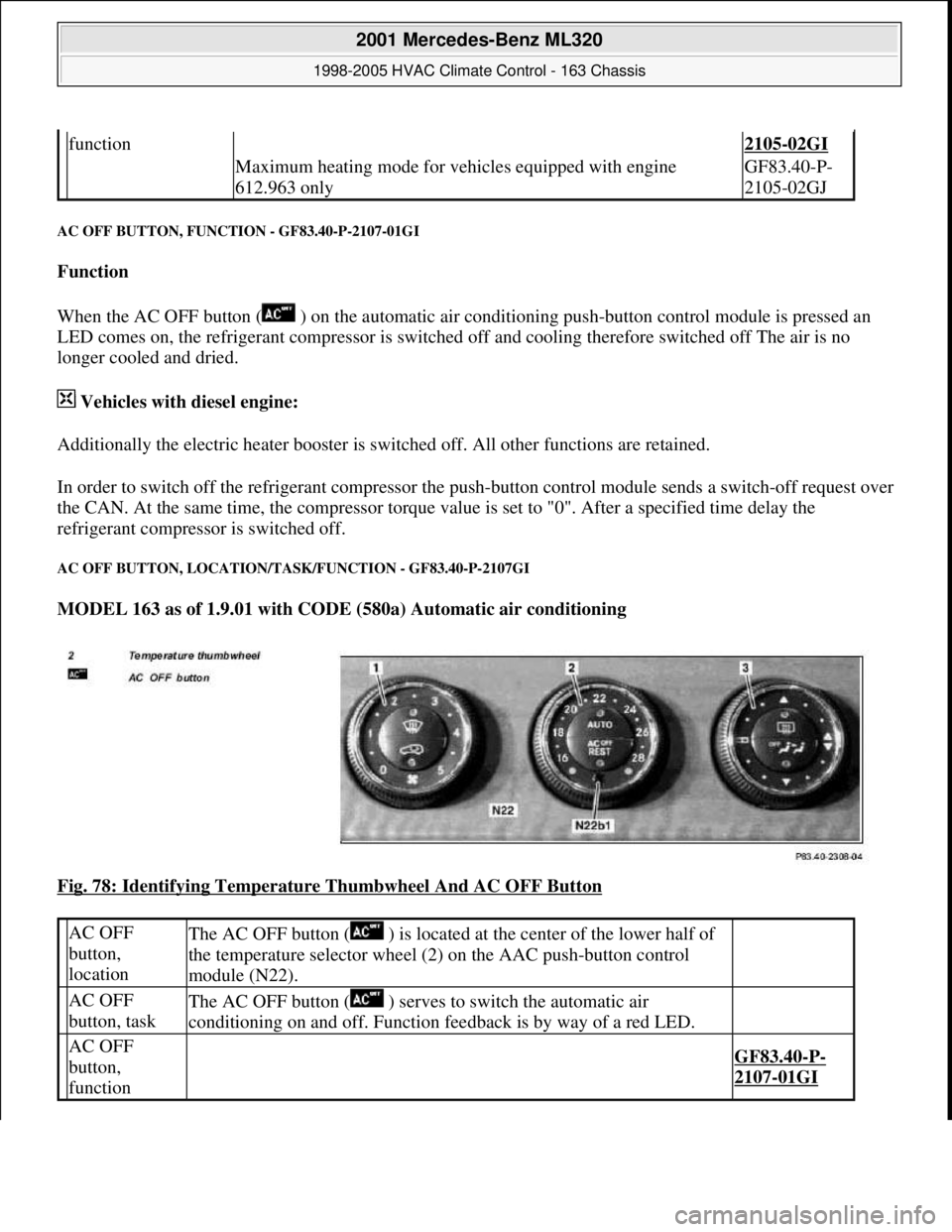
Fig. 78: Identifying Temperature Thumbwheel And AC OFF Button
function2105-02GI
Maximum heating mode for vehicles equipped with engine
612.963 onlyGF83.40-P-
2105-02GJ
AC OFF
button,
locationThe AC OFF button ( ) is located at the center of the lower half of
the temperature selector wheel (2) on the AAC push-button control
module (N22).
AC OFF
button, taskThe AC OFF button ( ) serves to switch the automatic air
conditioning on and off. Function feedback is by way of a red LED.
AC OFF
button,
function
GF83.40-P-
2107-01GI
2001 Mercedes-Benz ML320
1998-2005 HVAC Climate Control - 163 Chassis
me
Saturday, October 02, 2010 3:23:16 PMPage 96 © 2006 Mitchell Repair Information Company, LLC.
Page 3377 of 4133
ENGINE 111, 112, 271, 272, 611, 612, 646 in MODEL 203.7 with CODE (580) Air conditioning (or
Tempmatic for USA) with CODE (580) Automatic air conditioning with CODE (581) Automatic air
conditioning with CODE (581) Comfort automatic air conditioning
ENGINE 112.942 /970, 113.942 /965 /981, 612.963, 628.963 in MODEL 163 as of 1.9.01 with CODE (580)
Automatic air conditioning
ENGINE 112, 113, 271, 272, 273, 612, 642, 646 in MODEL 209.3
ENGINE 112, 113, 271, 272, 273, 642 in MODEL 209.4
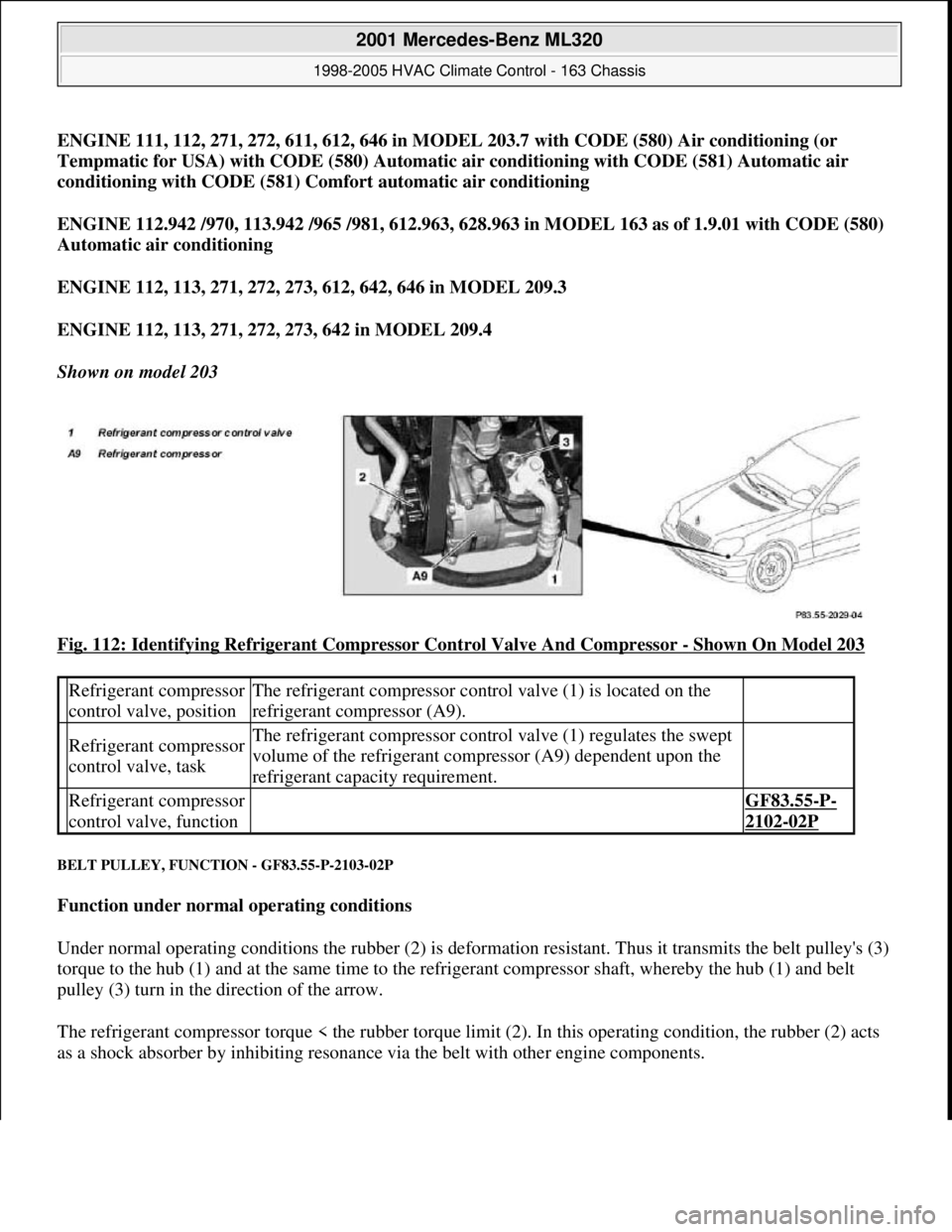
Shown on model 203
Fig. 112: Identifying Refrigerant Compressor Control Valve And Compressor
- Shown On Model 203
BELT PULLEY, FUNCTION - GF83.55-P-2103-02P
Function under normal operating conditions
Under normal operating conditions the rubber (2) is deformation resistant. Thus it transmits the belt pulley's (3)
torque to the hub (1) and at the same time to the refrigerant compressor shaft, whereby the hub (1) and belt
pulley (3) turn in the direction of the arrow.
The refrigerant compressor torque < the rubber torque limit (2). In this operating condition, the rubber (2) acts
as a shock absorber b
y inhibiting resonance via the belt with other engine components.
Refrigerant compressor
control valve, positionThe refrigerant compressor control valve (1) is located on the
refrigerant compressor (A9).
Refrigerant compressor
control valve, taskThe refrigerant compressor control valve (1) regulates the swept
volume of the refrigerant compressor (A9) dependent upon the
refrigerant capacity requirement.
Refrigerant compressor
control valve, function GF83.55-P-
2102-02P
2001 Mercedes-Benz ML320
1998-2005 HVAC Climate Control - 163 Chassis
me
Saturday, October 02, 2010 3:23:17 PMPage 133 © 2006 Mitchell Repair Information Company, LLC.
Page 3378 of 4133
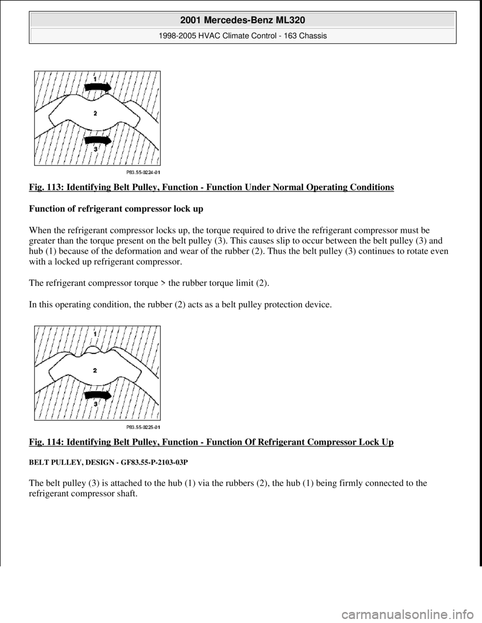
Fig. 113: Identifying Belt Pulley, Function - Function Under Normal Operating Conditions
Function of refrigerant compressor lock up
When the refrigerant compressor locks up, the torque re quired to drive the refrigerant compressor must be
greater than the torque present on the belt pulley (3). Th is causes slip to occur between the belt pulley (3) and
hub (1) because of the deformation and w ear of the rubber (2). Thus the belt pulley (3) continues to rotate even
with a locked up refrigerant compressor.
The refrigerant compressor torque > the rubber torque limit (2).
In this operating condition, the rubber (2) acts as a belt pulley protection device.
Fig. 114: Identifying Belt Pulley, Function
- Function Of Refrigerant Compressor Lock Up
BELT PULLEY, DESIGN - GF83.55-P-2103-03P
The belt pulley (3) is attached to the hub (1) via the rubbers (2), the hub (1) being firmly connected to the
refrigerant compressor shaft.
2001 Mercedes-Benz ML320
1998-2005 HVAC Climate Control - 163 Chassis
me
Saturday, October 02, 2010 3:23:17 PMPage 134 © 2006 Mitchell Repair Information Company, LLC.
Page 3380 of 4133
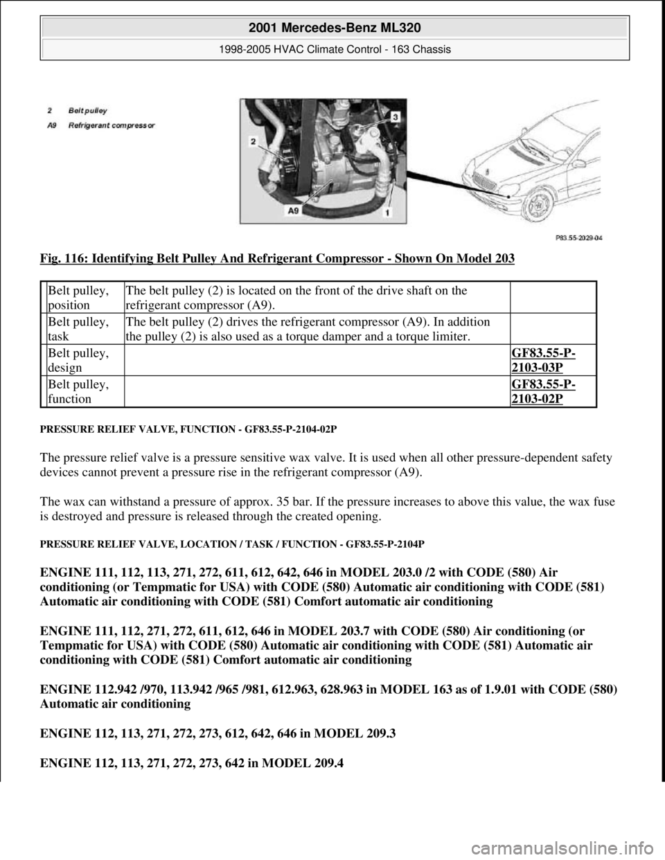
Fig. 116: Identifying Belt Pulley And Refrigerant Compressor - Shown On Model 203
PRESSURE RELIEF VALVE, FUNCTION - GF83.55-P-2104-02P
The pressure relief valve is a pressure sensitive wax valve. It is used when all other pressure-dependent safety
devices cannot prevent a pressure rise in the refrigerant compressor (A9).
The wax can withstand a pressure of approx. 35 bar. If the pressure increases to above this value, the wax fuse
is destroyed and pressure is released through the created opening.
PRESSURE RELIEF VALVE, LOCATION / TASK / FUNCTION - GF83.55-P-2104P
ENGINE 111, 112, 113, 271, 272, 611, 612, 642, 646 in MODEL 203.0 /2 with CODE (580) Air
conditioning (or Tempmatic for USA) with CODE (580) Automatic air conditioning with CODE (581)
Automatic air conditioning with CODE (581) Comfort automatic air conditioning
ENGINE 111, 112, 271, 272, 611, 612, 646 in MODEL 203.7 with CODE (580) Air conditioning (or
Tempmatic for USA) with CODE (580) Automatic air conditioning with CODE (581) Automatic air
conditioning with CODE (581) Comfort automatic air conditioning
ENGINE 112.942 /970, 113.942 /965 /981, 612.963, 628.963 in MODEL 163 as of 1.9.01 with CODE (580)
Automatic air conditioning
ENGINE 112, 113, 271, 272, 273, 612, 642, 646 in MODEL 209.3
ENGINE 112, 113, 271, 272, 273, 642 in MODEL 209.4
Belt pulley,
positionThe belt pulley (2) is located on the front of the drive shaft on the
refrigerant compressor (A9).
Belt pulley,
taskThe belt pulley (2) drives the refrigerant compressor (A9). In addition
the pulley (2) is also used as a torque damper and a torque limiter.
Belt pulley,
design GF83.55-P-
2103-03P
Belt pulley,
function GF83.55-P-
2103-02P
2001 Mercedes-Benz ML320
1998-2005 HVAC Climate Control - 163 Chassis
me
Saturday, October 02, 2010 3:23:17 PMPage 136 © 2006 Mitchell Repair Information Company, LLC.
Page 3479 of 4133

BT27.00-Z-9999AZ
Technical modifications: Passenger cars: Automatic transmission
30.4.97
MODEL all
Vacuum unit for modulating pressure modified
TRANSMISSION 722.3 /5 as of 15.8.92
BT27.10-P-0001-01A
Secondary pump dispensed with
TRANSMISSION 722.5## ## as of 3652931
BT27.10-P-0002-01A
Control pressure cable with vacuum actuators
standardized
TRANSMISSION 722.3 /4 /5 as of 1.7.93
BT27.10-P-0003-01A
Sump volume modified
TRANSMISSION 722.7## ## as of 0054011
as of 29.7.99
BT27.10-P-0004-01A
Additional shim between deep-groove ball
bearing and output flange
TRANSMISSION 722 ...
BT27.10-P-0005-01A
Oil pan and overflow tube modified
TRANSMISSION 722.901
BT27.10-P-0006-01W
Retaining lug added to electrohydraulic
control module
TRANSMISSION 722.6## # as of 0026195
BT27.19-P-0001-01A
Caps for solenoid valve, new
TRANSMISSION 722.6 as of 1.8.97
BT27.19-P-0003-01A
Oil drain plug on torque converter deleted
TRANSMISSION 722.6## /6## ## as of
1772285 as of 22.9.99
BT27.20-P-0001-01A
Small intermediate plate modified
TRANSMISSION 722.5## ## as of 3987361
as of 15.3.94
BT27.35-P-0001-01A
Installation of a pressure feed valve
TRANSMISSION 722.6## # as of 0027083
BT27.35-P-0002-01A
Primary pump non-return valve dispensed with
TRANSMISSION 722.5## ## as of 3652931
BT27.35-P-0003-01A
Strainer for modulating pressure and shift
pressure control solenoid valve, new
TRANSMISSION 722.6## ## as of 0538312
BT27.35-P-0004-01A
Strainer in inlet to converter lock-up control
solenoid valve, newTRANSMISSION 722.6## ## as of 0485895
BT27.35-P-0005-01A
Feed B1 enlarged
TRANSMISSION 722.5 as of 15.8.91
BT27.40-P-0001-01A
Fluid reservoir deleted
TRANSMISSION 722.7## ## as of 0111673
as of 11.9.00
BT27.40-P-0002-01A
Magnet in oil pan, new part
TRANSMISSION 722.6## ## as of 2871384
as of 17.4.01, 722.7## ## as of 0153700 as
of 9.7.01
BT27.40-P-0003-01A
Piston B1 modified
TRANSMISSION 722.5## ## as of 3746852
as of 15.6.92, 722.3## ## as of 3969172
BT27.50-P-0002-01A
Plain bearing of input shaft changed to an anti-
friction bearing
TRANSMISSION 722 ...
BT27.50-P-0002-02A
One-way valve dispensed with
TRANSMISSION 722.5## ## as of 3652931
BT27.50-P-0007-01A
Outer multiple-disc carrier B1 modified
TRANSMISSION 722.6## # as of 0005900
BT27.50-P-0008-01A
Peak-to-valley height on piston B2 modified
TRANSMISSION 722.6## # as of 0023104
BT27.50-P-0009-01A
Piston B2 changed
TRANSMISSION 722.6## ## as of 0552036
as of 1.8.97
BT27.50-P-0010-01A
Friction bearing in sun wheel of rear planet
gear set converted to anti-friction bearing
TRANSMISSION 722 ...
BT27.50-P-0011-01A
Conversion from 18° to 23° gearing in front
and rear planetary gear system
TRANSMISSION 722 ...
BT27.50-P-0012-01A
Multi-disks for B1, K1 and K3 changed
TRANSMISSION 722.6## ## as of 3947440
as of 2.9.02
BT27.50-P-0013-01A
Thickness of friction and steel disks K3
changed
TRANSMISSION 722.6
BT27.51-P-0001-01A
Thickness of steel plates of B1, K1 and K2
modified
TRANSMISSION 722.6## ## as of 1596205
as of 15.6.99
BT27.51-P-0002-01A
Additional dished washer in multi-plate set K2
TRANSMISSION 722.6## ## as of 1596205
as of 15.6.99
BT27.51-P-0003-01A
Center shift modified
TRANSMISSION 722.6
BT27.60-P-0001-01A
Deletion shift lock cable ignition lock to
transmission
TRANSMISSION 722.7 in MODEL
WDB168.### ## as of 548031 as of 10.1.01
BT27.60-P-0001-02A
Selector lever soldered
TRANSMISSION 722.6 as of 1.5.96
BT27.60-P-0002-01A
Deletion of lever for shift lock cable ignition
lock at transmission
TRANSMISSION 722.700 ## as of 0129631
as of 24.1.01, 722.701 ## as of 0132072 as
of 8.2.01
BT27.60-P-0003-01A
Copyright DaimlerChrysler AG 28.05.2006 CD-Ausgabe G/10/04 . This WIS print-out will not be recorde
d by Modification services.
Page 1
Page 3485 of 4133

Rims
D
When changing wheels, for instance, when replacing steel
wheels with light-alloy rims, ensure that the wheel bolts
required for the spare wheel are stored in a clearly visible
location.
D
Since December 1994 models 202 and 124 with special
equipment light alloy disk wheels, are supplied with a sheet
steel spare wheel instead of a light alloy spare wheel. The
necessary wheel bolts are included with the steel spare wheel.
D
Only use approved Mercedes-Benz rims of the same version.
D
Reinforced steel rims are identified by a sticker on the wheel
disc.
D
The wheel bolts on steel and light-alloy rims should always be
tightened to the specified tightening torque using a torque
wrench.
It is not necessary to retorque the lug bolts after approximately
100 to 500 km.
D
The seat for the tire bead must display no corrosion marks.
D
Before inserting a new rubber valve, clean the contact surfaces
on the disk wheel.
On sheet steel-disk wheel wheel trims must be fitted to support
the rubber valve.
Damaged or deformed rims must not be repaired.
Tire pressure monitor
D
Before replacing a tire, check the date of manufacturer of the
wheel sensor: wheel sensors which are more than 5 years old
must be replaced.
D
Use STAR DIAGNOSIS to read out the actual values of the tire
pressure monitor. Check the remaining life of the wheel sensor
battery, replace the wheel sensor if necessary.
Copyright DaimlerChrysler AG 06.07.2006 CD-Ausgabe G/10/04 . This WIS print-out will not be recorde
d by Modification services.
Page 2