Page 3714 of 4133
AH00.00-N-0001-01A
Notes on self-locking nuts and bolts
All models
Important repair information
Bolts with locking splines, micro-encapsulated bolts and self-
locking nuts must always be replaced after being used once.
There is an increased risk of injury when unscrewing micro-
encapsulated bolts due to the sudden breakaway torque.
Before new micro-encapsulated bolts are screwed in, the mating
thread must be re-cut in order to remove all the residue of the old bolt
locking compound.
Copyright DaimlerChrysler AG 06.07.2006 CD-Ausgabe G/10/04 . This WIS print-out will not be recorde
d by Modification services.
Page 1
Page 3717 of 4133
BT27.20-P-0001-01A
Oil drain plug on torque converter deleted
Transmission 722.6
k
TRANSMISSION
722.6## /6## ## as of 1772285 as of 22.9.99
For reasons of cost, the oil drain plug on the torque converter has
been deleted for all transmission variants.
Copyright DaimlerChrysler AG 28.05.2006 CD-Ausgabe G/10/04 . This WIS print-out will not be recorde
d by Modification services.
Page 1
Page 3842 of 4133
ENGINE 119.980 /981 /982 /985
ENGINE 137.970
Fig. 1: Identifying Electronic Accelerator Function
The function of the electronic accelerator pedal EFP in the ME control unit determines the opening angle of the
throttle valve over the actuator EFP/TPM/LLR (other designation: throttle valve actuator).
Further functions are:
Idle speed control [ISC]
Cruise control mode
Variable speed limiter
30 km/hour limit
Reduce/increase the engine torque for ASR/ESP operation
short performance limitation, for example for a higher coolant temperature
Emergency electronic accelerator pedal
Safety concept
Actuate indicator lamp EPC (up to 5/96)
Storing faults
Data exchanger via CAN
2001 Mercedes-Benz ML320
1998-2005 ACCESSORIES & BODY CAB Throttle Control, Speed Control Systems - 163 Chassis
me
Saturday, October 02, 2010 3:36:27 PMPage 2 © 2006 Mitchell Repair Information Company, LLC.
Page 3884 of 4133

Verify ground connection integrity between engine, body, battery and generator. Check for damaged wiring
harnesses and/or switches. Check fo r a broken or partially broken wire inside insulation, which could cause
system malfunction but prove good in a continuity/vol tage check with system disconnected. Ensure any
aftermarket electronic e quipment is properly installed. If fault is found, repair as necessary. If no fault is found,
check for conditions that might cause an intermittent situation.
SERVICE PRECAUTIONS
BATTERY DISCONNECT/CONNECT
Disconnect/Connect Procedures
1. Turn ignition off. Open engine hood. After opening ve hicle wait at least 4 minutes before disconnecting
battery or alarm wi ll be triggered.
2. Disconnect negative battery cable (1) and insulate cable lug to prevent unwanted contact with ground
point (W16/4). See Fig. 1
.
3. To connect, reverse disconnect procedur e. Tighten nut (5) to specification. See TORQUE
SPECIFICATIONS .
4. Perform basic programming, read Diagnostic Tr ouble Code (DTC) memory and erase DTCs from
memory. See BASIC PROGRAMMING
and RETRIEVING & ERASING DIAGNOSTIC
TROUBLE CODES .
NOTE: Numbers and letters in text refe
r to numbers and letters in figures.
2001 Mercedes-Benz ML320
2001-04 STARTING & CHARGING SYSTEMS Starters - 163 Chassis
me
Saturday, October 02, 2010 3:19:47 PMPage 2 © 2006 Mitchell Repair Information Company, LLC.
Page 3891 of 4133

Fig. 4: Connecting Hand Held Tester Scan Tool To OBD-II Data Link Connector
Courtesy of MERCEDES-BENZ OF NORTH AMERICA.
TESTING
Starter malfunctions may cause a Di agnostic Trouble Codes (DTCs) to be stored in Motor Electronics
Sequential Fuel Injection (ME-SFI) sy stem. After repairs are completed check for and erase any DTCs stored in
(ME-SFI) system. See appropriate SE LF-DIAGNOSTICS article in ENGINE PERFORMANCE. If cause of
starter malfunction is not engine pe rformance related, replace starter.
REMOVAL & INSTALLATION
STARTER
Removal & Installation
1. Disconnect and shield negative battery cable. See BATTERY DISCONNECT/CONNECT under
SERVICE PRECAUTIONS.
2. Remove nut (2) for inner fender. See Fig. 5
. Pull front and rear section of inner fender (1) downward.
Move inner fender away inward and downward. Pull toward outside over wheel. DO NOT damage fender
cutout or paint.
3. On vehicles with 112 engine, remove nut (6) at shield (5) of left engine mount and take out shield. See
Fig. 6
.
4. On all vehicles, disconnect circuit 30 (1) and circuit 50 (2) cables from starter. See Fig. 6
. Remove bolts
(3) for starter-to-crankcase. Take starter (M1) out to the side.
5. If replacing starter on vehicles with manual transmission, check ring gear at flywheel for wear and
damage. If replacing starter on vehicles with auto matic transmission, check ring gear on drive plate for
wear and damage. Repair or repl ace damaged parts as necessary.
6. To install, reverse removal proce dure. Replace bolts with locking splines, micro-encapsulated bolts and
self-locking nuts. Mating thread of mi cro-encapsulated bolts must be cleaned to remove all residue of old
bolt locking compound. Tighten fasteners to specification. See TORQUE SPECIFICATIONS
. Connect
battery. See BATTERY DISCONNECT/CONNECTunder SERVICE PRECAUTIONS.
NOTE: Numbers and letters in text refe
r to numbers and letters in figures.
2001 Mercedes-Benz ML320
2001-04 STARTING & CHARGING SYSTEMS Starters - 163 Chassis
me
Saturday, October 02, 2010 3:19:47 PMPage 9 © 2006 Mitchell Repair Information Company, LLC.
Page 3893 of 4133
Fig. 6: Removing Starter
Courtesy of MERCEDES-BENZ OF NORTH AMERICA.
OVERHAUL
TORQUE SPECIFICATIONS
TORQUE SPECIFICATIONS
NOTE: Manufacturer does not r ecommend overhaul of starter.
ApplicationFt. Lbs. (N.m)
2001 Mercedes-Benz ML320
2001-04 STARTING & CHARGING SYSTEMS Starters - 163 Chassis
me
Saturday, October 02, 2010 3:19:47 PMPage 11 © 2006 Mitchell Repair Information Company, LLC.
Page 3901 of 4133

GF54.30-P-3009A
Stepper motor, location/design/function
7.7.99
MODEL
129, 140 as of 1.6.96,
163, 168, 170,
202 as of 1.8.96,
208,
210 as of 1.6.96,
215, 220
P54.30-0521-06
General
Stepper motors are motors which, like most
electric motors, consist of a fixed stator and a
moveable rotor. The rotary motion is not
continuous, rather the rotor turns in steps, a
certain angle at a time, for example 90°.
Design
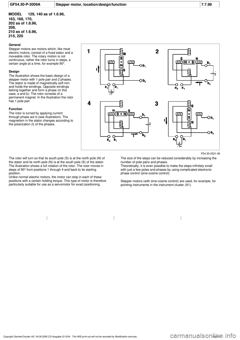
The illustration shows the basic design of a
stepper motor with 1 pole pair and 2 phases.
The stator is made of magnetically soft iron
and holds the windings. Opposite windings
belong together and form a phase (in this
case, a and b). The rotor consists of a
permanent magnet. In the illustration the rotor
has 1 pole pair.
Function
The rotor is turned by applying current
through phase aor b (see illustration). The
magnetism in the stator changes according to
the polarization (I) of the phases.
The rotor will turn so that its south pole (S) is at the north pole (N) of
the stator and its north pole (N) is at the south pole (S) of the stator.
The illustration shows a full rotation of the rotor. The rotor moves in
steps of 90° from positions 1 through 4 and back to its starting
position.
Unlike normal electric motors, the motor can stop in each of these
positions with a certain holding torque. This type of motor is therefore
particularly suitable for use as a servomotor for exact positioning.
The size of the steps can be reduced considerably by increasing the
number of pole pairs and phases.
Theoretically, it is even possible to make the steps infinitely small
with just a few poles and phases by using complicated electronic
phase control (sine-cosine control).
Stepper motors (with sine-cosine control) are used, for example, for
pointing instruments in the instrument cluster (A1).
Copyright DaimlerChrysler AG 04.06.2006 CD-Ausgabe G/10/04 . This WIS print-out will not be recorde
d by Modification services.
Page 1
Page 3935 of 4133

Rear axle shock absorber
Wheel location
REMOVAL & INSTALLATION
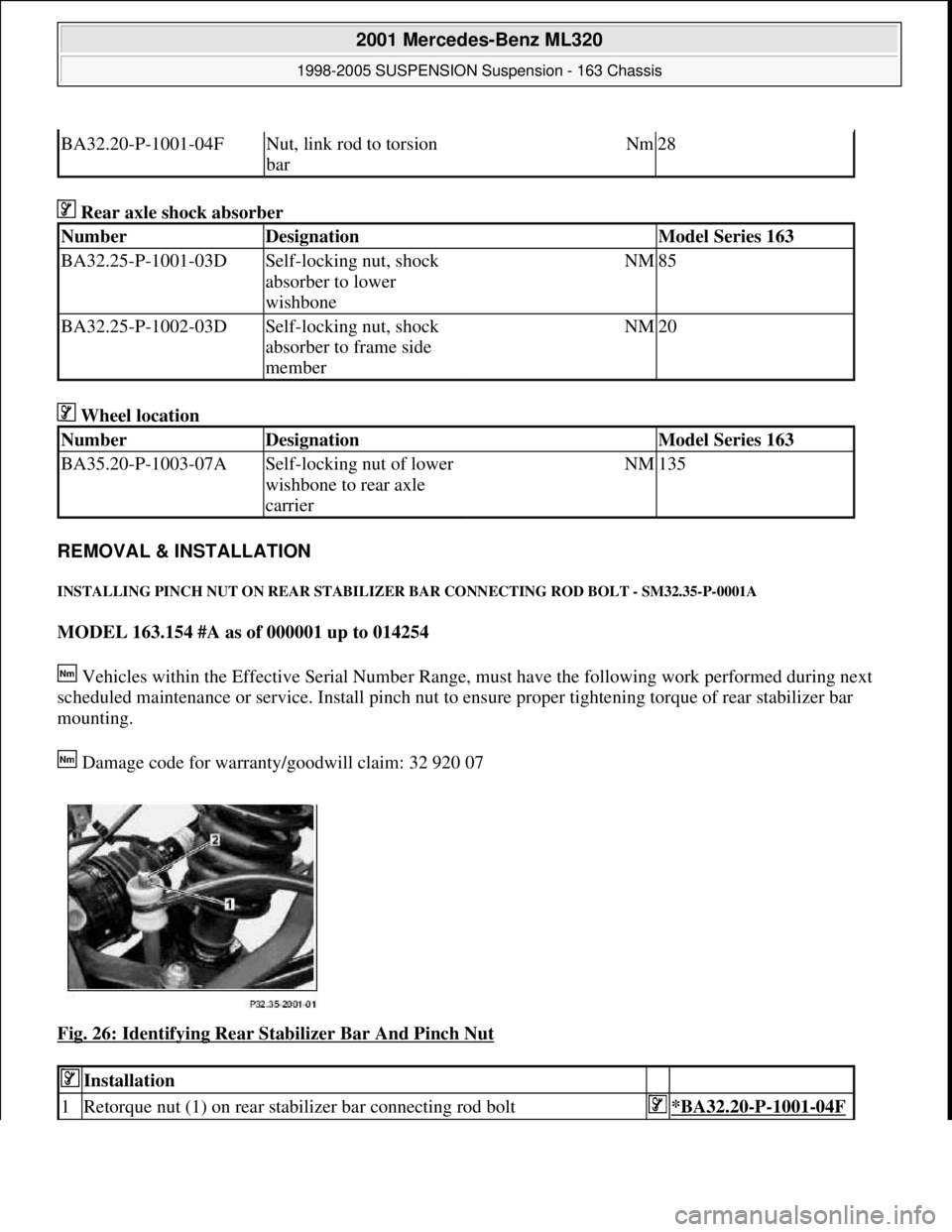
INSTALLING PINCH NUT ON REAR STABILIZER BAR CONNECTING ROD BOLT - SM32.35-P-0001A
MODEL 163.154 #A as of 000001 up to 014254
Vehicles within the Effective Serial Number Range, must have the following work performed during next
scheduled maintenance or service. Install pinch nut to ensure proper tightening torque of rear stabilizer bar
mounting.
Damage code for warranty/goodwill claim: 32 920 07
Fig. 26: Identifying Rear Stabilizer Bar And Pinch Nut
BA32.20-P-1001-04FNut, link rod to torsion
barNm28
NumberDesignationModel Series 163
BA32.25-P-1001-03DSelf-locking nut, shock
absorber to lower
wishboneNM85
BA32.25-P-1002-03DSelf-locking nut, shock
absorber to frame side
memberNM20
NumberDesignationModel Series 163
BA35.20-P-1003-07ASelf-locking nut of lower
wishbone to rear axle
carrierNM135
Installation
1Retorque nut (1) on rear stabilizer bar connecting rod bolt*BA32.20-P-1001-04F
2001 Mercedes-Benz ML320
1998-2005 SUSPENSION Suspension - 163 Chassis
me
Saturday, October 02, 2010 3:37:36 PMPage 27 © 2006 Mitchell Repair Information Company, LLC.