1997 MERCEDES-BENZ ML430 torque
[x] Cancel search: torquePage 3153 of 4133
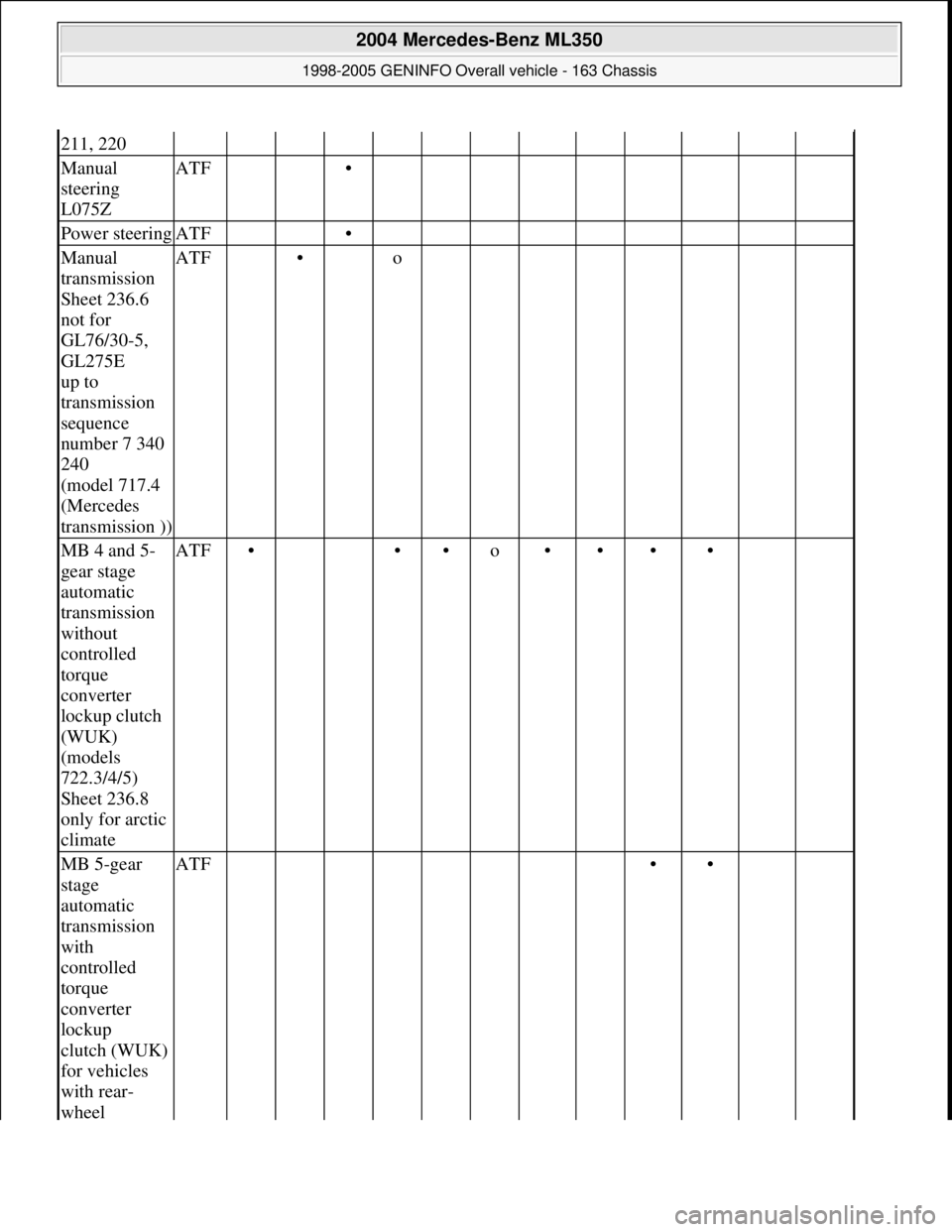
211, 220
Manual
steering
L075ZATF •
Power steeringATF •
Manual
transmission
Sheet 236.6
not for
GL76/30-5,
GL275E
up to
transmission
sequence
number 7 340
240
(model 717.4
(Mercedes
transmission ))ATF • o
MB 4 and 5-
gear stage
automatic
transmission
without
controlled
torque
converter
lockup clutch
(WUK)
(models
722.3/4/5)
Sheet 236.8
only for arctic
climateATF• ••o••••
MB 5-gear
stage
automatic
transmission
with
controlled
torque
converter
lockup
clutch (WUK)
for vehicles
with rear-
wheel ATF ••
2004 Mercedes-Benz ML350
1998-2005 GENINFO Overall vehicle - 163 Chassis
me
Saturday, October 02, 2010 3:47:56 PMPage 508 © 2006 Mitchell Repair Information Company, LLC.
Page 3154 of 4133
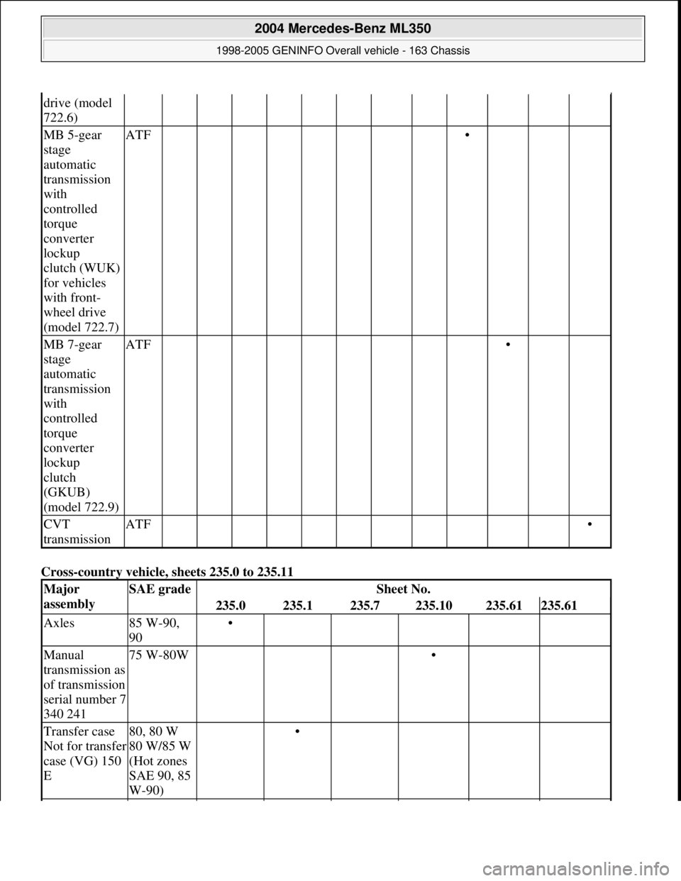
Cross-country vehicle, sheets 235.0 to 235.11
drive (model
722.6)
MB 5-gear
stage
automatic
transmission
with
controlled
torque
converter
lockup
clutch (WUK)
for vehicles
with front-
wheel drive
(model 722.7)ATF •
MB 7-gear
stage
automatic
transmission
with
controlled
torque
converter
lockup
clutch
(GKUB)
(model 722.9)ATF •
CVT
transmissionATF •
Major
assemblySAE gradeSheet No.
235.0235.1235.7235.10235.61235.61
Axles85 W-90,
90•
Manual
transmission as
of transmission
serial number 7
340 24175 W-80W •
Transfer case
Not for transfer
case (VG) 150
E80, 80 W
80 W/85 W
(Hot zones
SAE 90, 85
W-90) •
2004 Mercedes-Benz ML350
1998-2005 GENINFO Overall vehicle - 163 Chassis
me
Saturday, October 02, 2010 3:47:56 PMPage 509 © 2006 Mitchell Repair Information Company, LLC.
Page 3155 of 4133
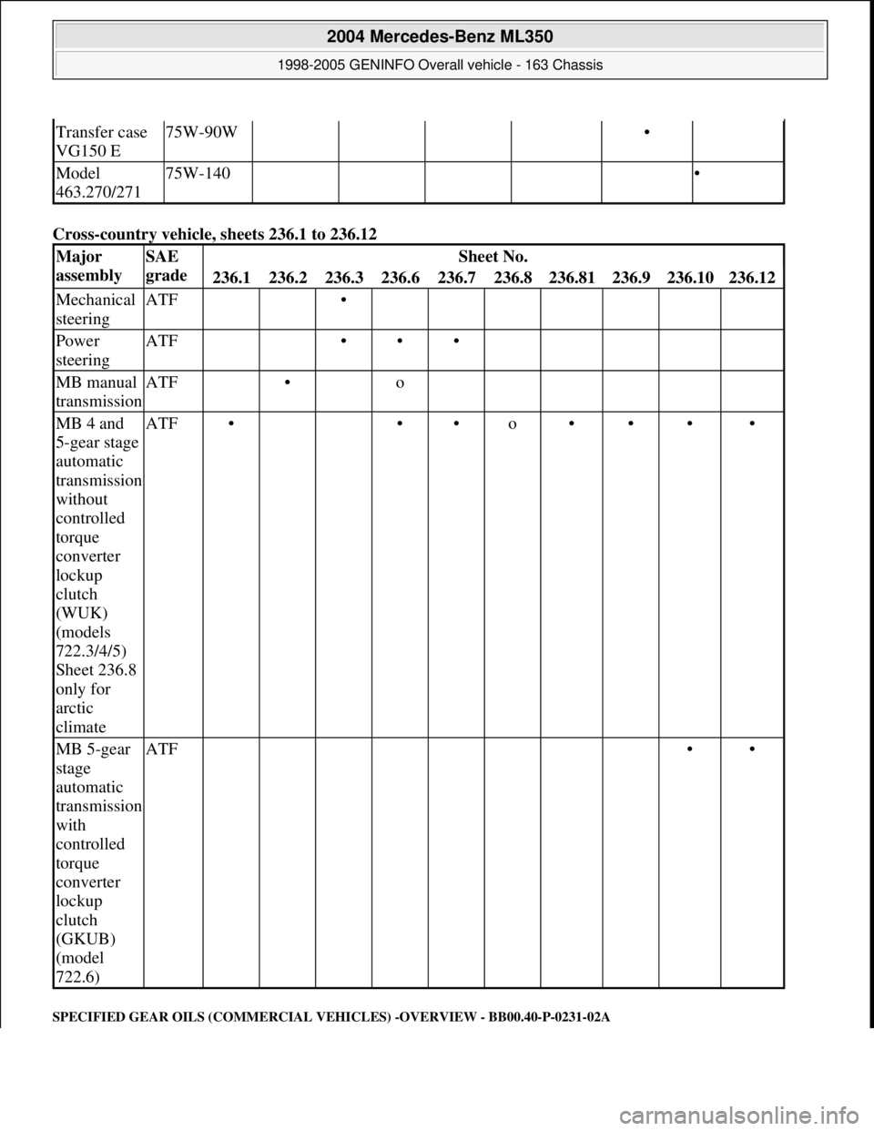
Cross-country vehicle, sheets 236.1 to 236.12
SPECIFIED GEAR OILS (COMMERCIAL VEHICLES) -OVERVIEW - BB00.40-P-0231-02A
Transfer case
VG150 E75W-90W •
Model
463.270/27175W-140 •
Major
assemblySAE
gradeSheet No.
236.1236.2236.3236.6236.7236.8236.81236.9236.10236.12
Mechanical
steeringATF •
Power
steeringATF •••
MB manual
transmissionATF • o
MB 4 and
5-gear stage
automatic
transmission
without
controlled
torque
converter
lockup
clutch
(WUK)
(models
722.3/4/5)
Sheet 236.8
only for
arctic
climateATF• ••o••••
MB 5-gear
stage
automatic
transmission
with
controlled
torque
converter
lockup
clutch
(GKUB)
(model
722.6)ATF ••
2004 Mercedes-Benz ML350
1998-2005 GENINFO Overall vehicle - 163 Chassis
me
Saturday, October 02, 2010 3:47:56 PMPage 510 © 2006 Mitchell Repair Information Company, LLC.
Page 3158 of 4133
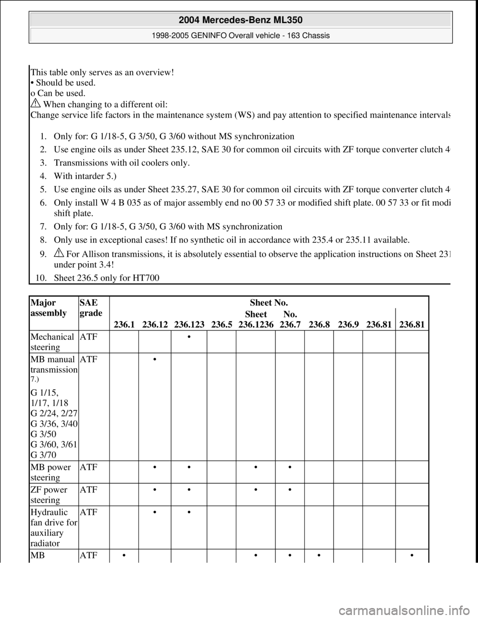
This table only serves as an overview!
• Should be used.
o Can be used.
When changing to a different oil:
Change service life factors in the maintenance system (WS) and pay attention to specified maintenance interval
s
1. Only for: G 1/18-5, G 3/50, G 3/60 without MS synchronization
2. Use engine oils as under Sheet 235.12, SAE 30 for common oil circuits with ZF torque converter clutch 4
0
3. Transmissions with oil coolers only.
4. With intarder 5.)
5. Use engine oils as under Sheet 235.27, SAE 30 for common oil circuits with ZF torque converter clutch 4
0
6. Only install W 4 B 035 as of major assembly end no 00 57 33 or modified shift plate. 00 57 33 or fit modi
shift plate.
7. Only for: G 1/18-5, G 3/50, G 3/60 with MS synchronization
8. Only use in exceptional cases! If no synthetic oil in accordance with 235.4 or 235.11 available.
9. For Allison transmissions, it is absolutely essential to observe the application instructions on Sheet 23
1
under point 3.4!
10. Sheet 236.5 only for HT700
Major
assemblySAE
gradeSheet No.
236.1236.12236.123236.5
Sheet
236.1236No.
236.7
236.8236.9236.81236.81
Mechanical
steeringATF •
MB manual
transmission
7.)
G 1/15,
1/17, 1/18
G 2/24, 2/27
G 3/36, 3/40
G 3/50
G 3/60, 3/61
G 3/70
ATF •
MB power
steeringATF •• ••
ZF power
steeringATF •• ••
Hydraulic
fan drive for
auxiliary
radiatorATF ••
MB ATF• ••• •
2004 Mercedes-Benz ML350
1998-2005 GENINFO Overall vehicle - 163 Chassis
me
Saturday, October 02, 2010 3:47:56 PMPage 513 © 2006 Mitchell Repair Information Company, LLC.
Page 3159 of 4133
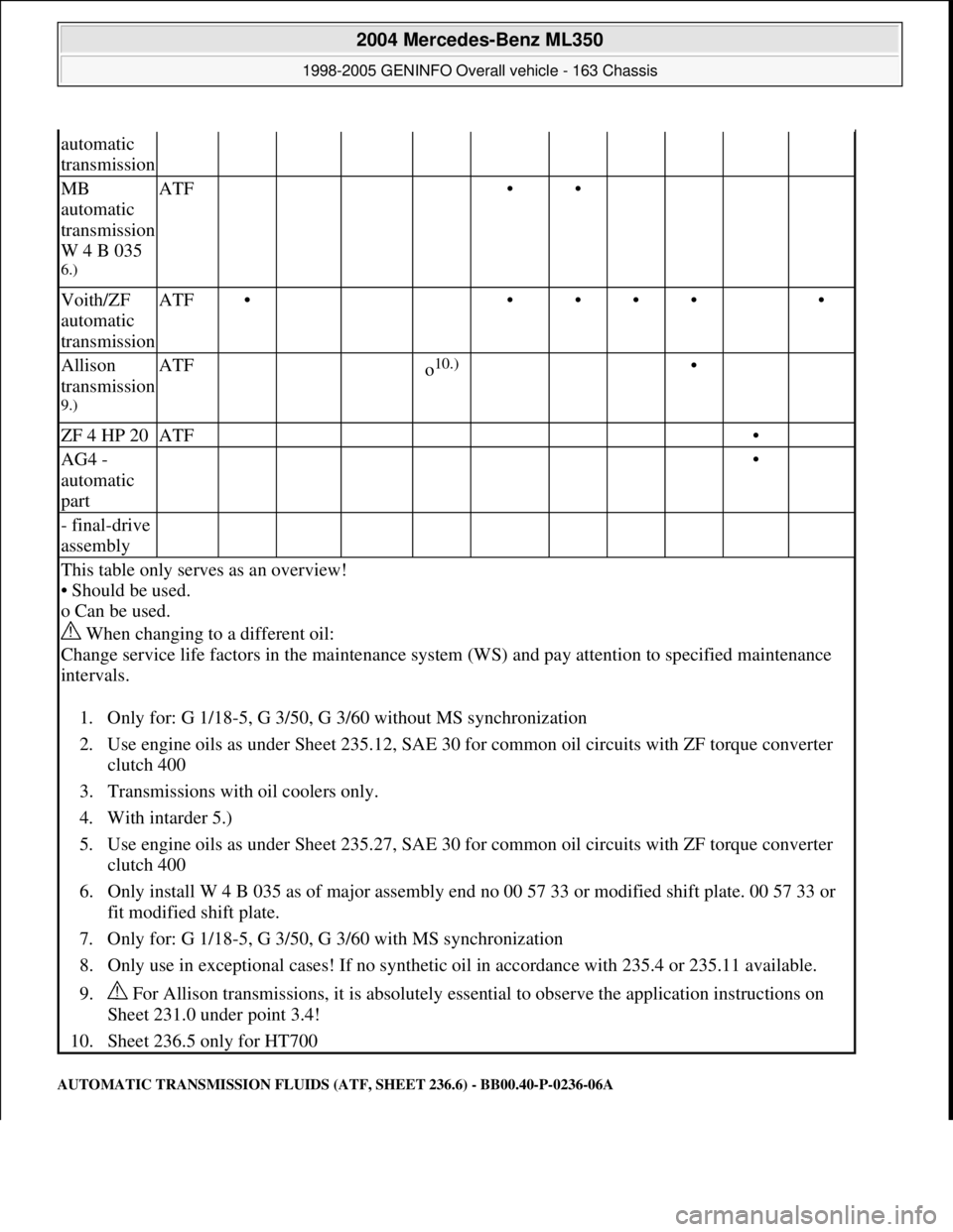
AUTOMATIC TRANSMISSION FLUIDS (ATF, SHEET 236.6) - BB00.40-P-0236-06A
automatic
transmission
MB
automatic
transmission
W 4 B 035
6.)
ATF ••
Voith/ZF
automatic
transmissionATF• •••• •
Allison
transmission
9.)
ATF o10.) •
ZF 4 HP 20ATF •
AG4 -
automatic
part •
- final-drive
assembly
This table only serves as an overview!
• Should be used.
o Can be used.
When changing to a different oil:
Change service life factors in the maintenance system (WS) and pay attention to specified maintenance
intervals.
1. Only for: G 1/18-5, G 3/50, G 3/60 without MS synchronization
2. Use engine oils as under Sheet 235.12, SAE 30 for common oil circuits with ZF torque converter
clutch 400
3. Transmissions with oil coolers only.
4. With intarder 5.)
5. Use engine oils as under Sheet 235.27, SAE 30 for common oil circuits with ZF torque converter
clutch 400
6. Only install W 4 B 035 as of major assembly end no 00 57 33 or modified shift plate. 00 57 33 or
fit modified shift plate.
7. Only for: G 1/18-5, G 3/50, G 3/60 with MS synchronization
8. Only use in exceptional cases! If no synthetic oil in accordance with 235.4 or 235.11 available.
9. For Allison transmissions, it is absolutely essential to observe the application instructions on
Sheet 231.0 under point 3.4!
10. Sheet 236.5 only for HT700
2004 Mercedes-Benz ML350
1998-2005 GENINFO Overall vehicle - 163 Chassis
me
Saturday, October 02, 2010 3:47:56 PMPage 514 © 2006 Mitchell Repair Information Company, LLC.
Page 3228 of 4133
A/C housing. Disconnect control module connector. To install reverse removal procedure. Recode 5-digit radio
security code. Using HHT, check for DTC and erase, and set clock.
A/C PUSH BUTTON CONTROL PANEL
Removal & Installation
1. Obtain 5-digit radio security code from vehicle owner. Disconnect negative battery cable. Using radio
removal plates, remove radio. Disconnect electrical connectors.
2. Remove instrument panel center section. Remove 4 A/C control panel screws and remove control panel.
Release pull cables and disconnect connectors. To install, reverse removal procedure. Recode radio. See
RECODING RADIO
under PROGRAMMING.
BLOWER MOTOR
Removal & Installation
Remove passenger-side instrument panel under cover. Remove blower motor mounting screws from A/C
housing unit. Disconnect blower motor connector and remove blower motor. To install, reverse removal
procedure.
COMPRESSOR
Removal & Installation
1. Discharge A/C system, using approved refrigerant recovery/recycling equipment. Remove accessory
drive belt. Disconnect low pressure refrigerant line from compressor. Discard "O" rings. Plug exposed
openings to protect A/C system from debris and moisture.
2. Disconnect high pressure refrigerant line from compressor. Discard "O" rings. Plug exposed openings to
protect A/C system from debris and moisture. Disconnect electrical connector. Remove compressor
mounting bolts.
3. Raise and support vehicle. Remove compressor from under vehicle without spilling refrigerant oil. To
install, reverse removal procedure. Ensure refrigerant oil quantity in compressor is correct. See
COMPRESSOR REFRIGERANT OIL CHECKING under GENERAL SERVICING. Tighten bolts to
specification. See TORQUE SPECIFICATIONS
.
CONDENSER
Removal & Installation
1. Discharge A/C system, using approved refrigerant recovery/recycling equipment. Remove cooling fans.
See COOLING FANS
. Disconnect refrigerant line from receiver-drier. See Fig. 5 . Discard "O" rings.
2. Plug exposed openings to protect A/C system from debris and moisture. Remove refrigerant line from
condenser. Remove radiator upper rubber seal. See Fig. 6
. Remove condenser upper mounting screws.
Lift condenser upward and remove. NOTE: Each time A/C compressor is removed and installed, receiver-drier must be
replaced.
2001 Mercedes-Benz ML320
2000-01 MANUAL A/C-HEATER SYSTEMS ML 320, ML 430 & ML 55
me
Saturday, October 02, 2010 3:25:10 PMPage 17 © 2006 Mitchell Repair Information Company, LLC.
Page 3229 of 4133

3. To install, reverse removal procedure. Use NEW "O" rings lubricated with refrigerant oil. If installing a
new or repaired condenser, add 0.68 ounce of NEW refrigerant oil to condenser. Tighten refrigerant line
bolts to specification. See TORQUE SPECIFICATIONS.
2001 Mercedes-Benz ML320
2000-01 MANUAL A/C-HEATER SYSTEMS ML 320, ML 430 & ML 55
me
Saturday, October 02, 2010 3:25:10 PMPage 18 © 2006 Mitchell Repair Information Company, LLC.
Page 3232 of 4133
Fig. 6: Removing Cooling Fans & Condenser
Courtesy of MERCEDES-BENZ OF NORTH AMERICA.
COOLING FANS
Removal & Installation
Remove headlight units. Remove upper frame crossmember, release hood release control cable and remove
crossmember. See Fig. 6
. Remove 2 cooling fans frame bolts on radiator. Disconnect cooling fan connector.
Release outside temperature sensor wiring harness. Pull up on cooling fan and remove. To install, reverse
removal procedure. Ensure cooling fan bottom guides are properly seated in lower mounts.
EVAPORATOR
Removal & Installation
Remove A/C housing unit. See A/C HOUSING UNIT . Remove expansion valve. See Fig. 5 . Discard "O"
rings. Disassemble A/C housing unit. Remove evaporator. Remove evaporator temperature sensor. To install,
reverse removal procedure. Use NEW "O" rings lubricated with refrigerant oil. If installing a new or repair
evaporator, add 1.35 ounces of NEW refrigerant oil to evaporator.
EXPANSION VALVE
Removal & Installation
1. Discharge A/C system, using approved refrigerant recovery/recycling equipment. Without disconnecting
coolant hoses, remove coolant expansion reservoir and set aside. Remove refrigerant line bracket and
loosen clamps. See Fig. 5
. Pull refrigerant lines out of expansion valve.
2. Remove expansion valve self-locking nut and discard. Remove expansion valve. Discard "O" rings. To
install, reverse removal procedure. Use NEW "O" rings lubricated with refrigerant oil. Tighten NEW self-
locking nut to specification. See TORQUE SPECIFICATIONS
.
INSTRUMENT PANEL & INSTRUMENT PANEL CARRIER
Removal & Installation
1. Secure vehicle against rolling. Set transmission selector to "D" position. Obtain radio security code.
Disconnect negative battery cable. Remove driver-side air bag.
2. Place match marks on steering wheel and steering shaft. Remove steering wheel, upper steering column
covers and combination switch. Remove instrument cluster cover frame. Remove one instrument panel
lower section bolt.
3. Remove screws in footwell from left side of instrument panel bottom section. Remove instrument panel
center section. Remove 4 A/C control panel screws and remove control panel. See Fig. 1
. Release pull
cables and disconnect connectors.
4. Remove screws from center section. Remove glove box. Remove screws in footwell from right side of
instrument panel bottom section. Remove entry courtesy lights. Remove end covers and screws.
5. Release 4 "A" clips between instrument panel bottom section and upper section. See Fig. 7
. Release
parkin
g brake release cable from handle. With assistance, remove instrument panel bottom section.
2001 Mercedes-Benz ML320
2000-01 MANUAL A/C-HEATER SYSTEMS ML 320, ML 430 & ML 55
me
Saturday, October 02, 2010 3:25:10 PMPage 21 © 2006 Mitchell Repair Information Company, LLC.