Page 2324 of 4133
Fig. 87: Identifying Insertion Tool (112 589 01 03 00)
Fig. 88: Identifying Torque Wrench (001 589 72 21 00)
Fig. 89: Identifying Valve Assemb ly Tool Case (111 589 25 61 00)
Fig. 90: Identifying Magnet Finger (116 589 06 63 00)
Commercially available tools
NumberDesignation
WH58.30-Z-1040-02ATweezers, straight 160 mm with rounded tips
2004 Mercedes-Benz ML350
1998-2005 ENGINE Engine timing - 163 Chassis
me
Saturday, October 02, 2010 3:39:38 PMPage 83 © 2006 Mitchell Repair Information Company, LLC.
Page 2407 of 4133
Shown on engine 112.942
Fig. 45: Identifying Torque Converter
- Shown On Engine 112.942
Shown on engine 112.942
Fig. 46: Identifying Starter Ring Gear
- Shown On Engine 112.942
Shown on engine 112.942
2001 Mercedes-Benz ML320
1998-2005 ENGINE Complete engine - 163 Chassis
me
Saturday, October 02, 2010 3:17:56 PMPage 51 © 2006 Mitchell Repair Information Company, LLC.
Page 2408 of 4133
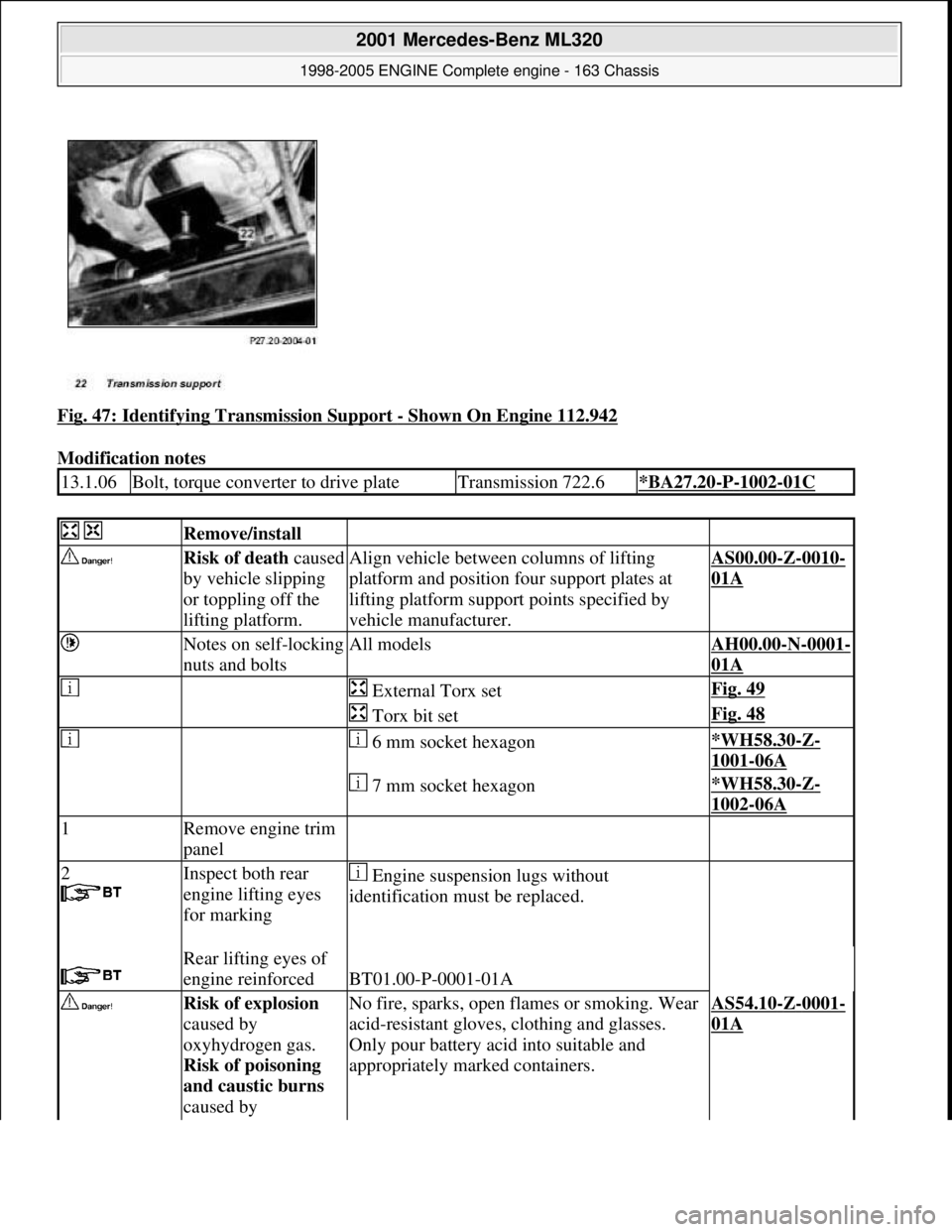
Fig. 47: Identifying Transmission Support - Shown On Engine 112.942
Modification notes
13.1.06Bolt, torque converter to drive plateTransmission 722.6*BA27.20-P-1002-01C
Remove/install
Risk of death caused
by vehicle slipping
or toppling off the
lifting platform.Align vehicle between columns of lifting
platform and position f our support plates at
lifting platform suppor t points specified by
vehicle manufacturer.AS00.00-Z-0010-
01A
Notes on self-locking
nuts and boltsAll modelsAH00.00-N-0001-
01A
External Torx setFig. 49
Torx bit setFig. 48
6 mm socket hexagon*WH58.30-Z-
1001-06A
7 mm socket hexagon*WH58.30-Z-
1002-06A
1Remove engine trim
panel
2
Inspect both rear
engine lifting eyes
for marking
Engine suspensi on lugs without
identification must be replaced.
Rear lifting eyes of
engine reinforced
BT01.00-P-0001-01A
Risk of explosion
caused by
oxyhydrogen gas.
Risk of poisoning
and caustic burns
caused by No fire, sparks, open fl ames or smoking. Wear
acid-resistant gloves, clothing and glasses.
Only pour battery acid into suitable and
appropriately marked containers.AS54.10-Z-0001-
01A
2001 Mercedes-Benz ML320
1998-2005 ENGINE Complete engine - 163 Chassis
me
Saturday, October 02, 2010 3:17:56 PMPage 52 © 2006 Mitchell Repair Information Company, LLC.
Page 2412 of 4133
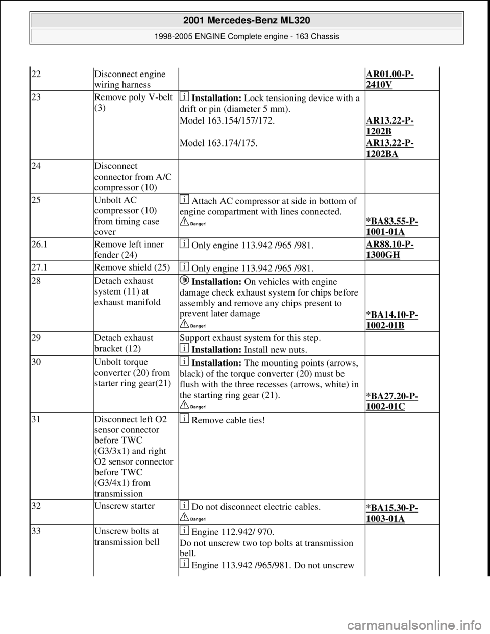
22Disconnect engine
wiring harness AR01.00-P-
2410V
23Remove poly V-belt
(3) Installation: Lock tensioning device with a
drift or pin (diameter 5 mm).
Model 163.154/157/172.AR13.22-P-
1202B
Model 163.174/175.AR13.22-P-
1202BA
24Disconnect
connector from A/C
compressor (10)
25Unbolt AC
compressor (10)
from timing case
cover Attach AC compressor at side in bottom of
engine compartment with lines connected.
*BA83.55-P-
1001-01A
26.1Remove left inner
fender (24) Only engine 113.942 /965 /981.AR88.10-P-
1300GH
27.1Remove shield (25) Only engine 113.942 /965 /981.
28Detach exhaust
system (11) at
exhaust manifold Installation: On vehicles with engine
damage check exhaust sy stem for chips before
assembly and remove any chips present to
prevent later damage
*BA14.10-P-
1002-01B
29Detach exhaust
bracket (12)Support exhaust system for this step.
Installation: Install new nuts.
30Unbolt torque
converter (20) from
starter ring gear(21) Installation: The mounting points (arrows,
black) of the torque converter (20) must be
flush with the three recesses (arrows, white) in
the starting ring gear (21).
*BA27.20-P-
1002-01C
31Disconnect left O2
sensor connector
before TWC
(G3/3x1) and right
O2 sensor connector
before TWC
(G3/4x1) from
transmission Remove cable ties!
32Unscrew starter Do not disconnect electric cables.
*BA15.30-P-
1003-01A
33Unscrew bolts at
transmission bell Engine 112.942/ 970.
Do not unscrew two top bolts at transmission
bell.
Engine 113.942 /965/ 981. Do not unscrew
2001 Mercedes-Benz ML320
1998-2005 ENGINE Complete engine - 163 Chassis
me
Saturday, October 02, 2010 3:17:56 PMPage 56 © 2006 Mitchell Repair Information Company, LLC.
Page 2413 of 4133
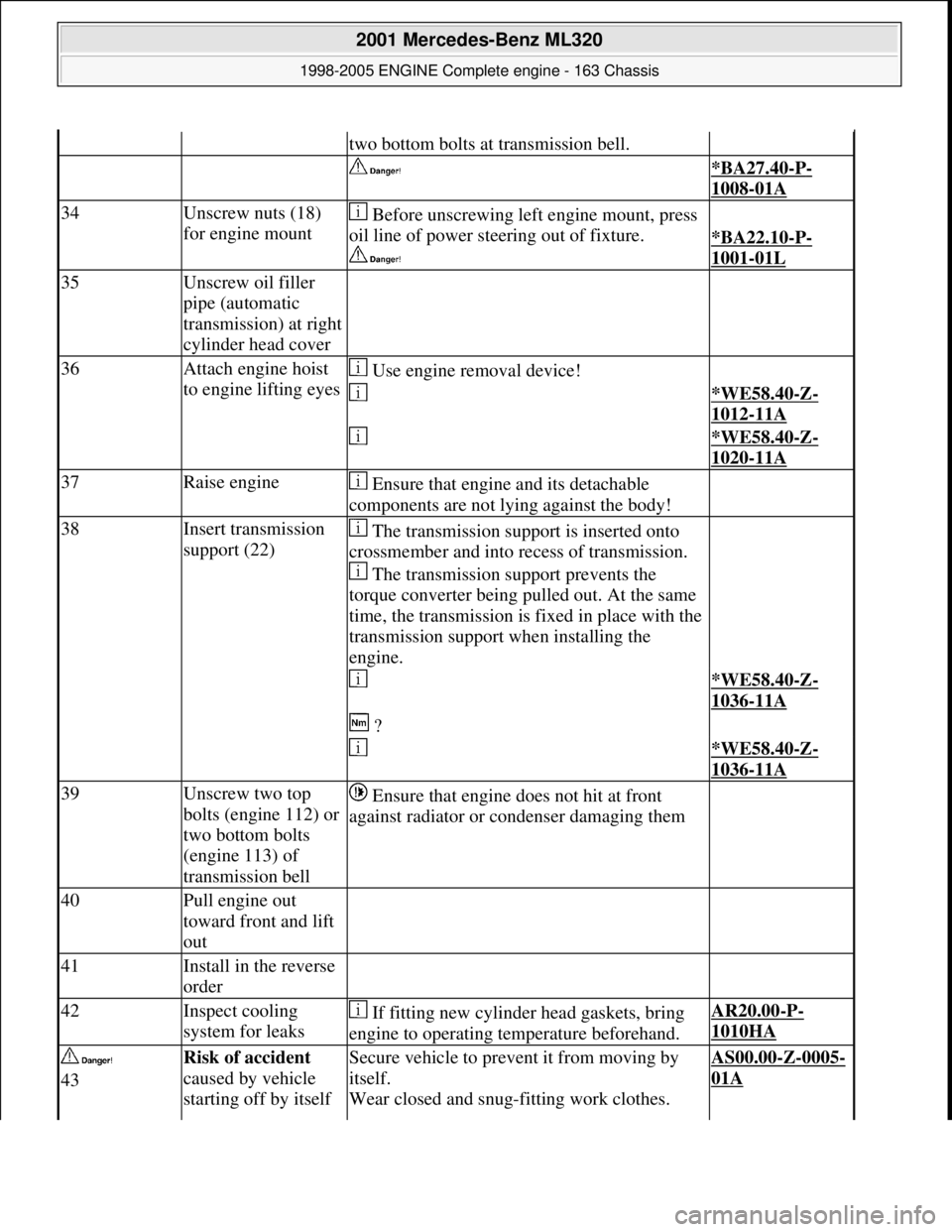
two bottom bolts at transmission bell.
*BA27.40-P-
1008-01A
34Unscrew nuts (18)
for engine mount Before unscrewing left engine mount, press
oil line of power stee ring out of fixture.
*BA22.10-P-
1001-01L
35Unscrew oil filler
pipe (automatic
transmission) at right
cylinder head cover
36Attach engine hoist
to engine lifting eyes Use engine removal device!
*WE58.40-Z-
1012-11A
*WE58.40-Z-
1020-11A
37Raise engine Ensure that engine and its detachable
components are not lying against the body!
38Insert transmission
support (22) The transmission support is inserted onto
crossmember and into recess of transmission.
The transmission support prevents the
torque converter being pulled out. At the same
time, the transmission is fixed in place with the
transmission support when installing the
engine.
*WE58.40-Z-
1036-11A
?
*WE58.40-Z-
1036-11A
39Unscrew two top
bolts (engine 112) or
two bottom bolts
(engine 113) of
transmission bell Ensure that engine does not hit at front
against radiator or condenser damaging them
40Pull engine out
toward front and lift
out
41Install in the reverse
order
42Inspect cooling
system for leaks If fitting new cylinder head gaskets, bring
engine to operating temperature beforehand.AR20.00-P-
1010HA
43Risk of accident
caused by vehicle
starting off by itself Secure vehicle to prev ent it from moving by
itself.
Wear closed and snug-fitting work clothes. AS00.00-Z-0005-
01A
2001 Mercedes-Benz ML320
1998-2005 ENGINE Complete engine - 163 Chassis
me
Saturday, October 02, 2010 3:17:56 PMPage 57 © 2006 Mitchell Repair Information Company, LLC.
Page 2415 of 4133
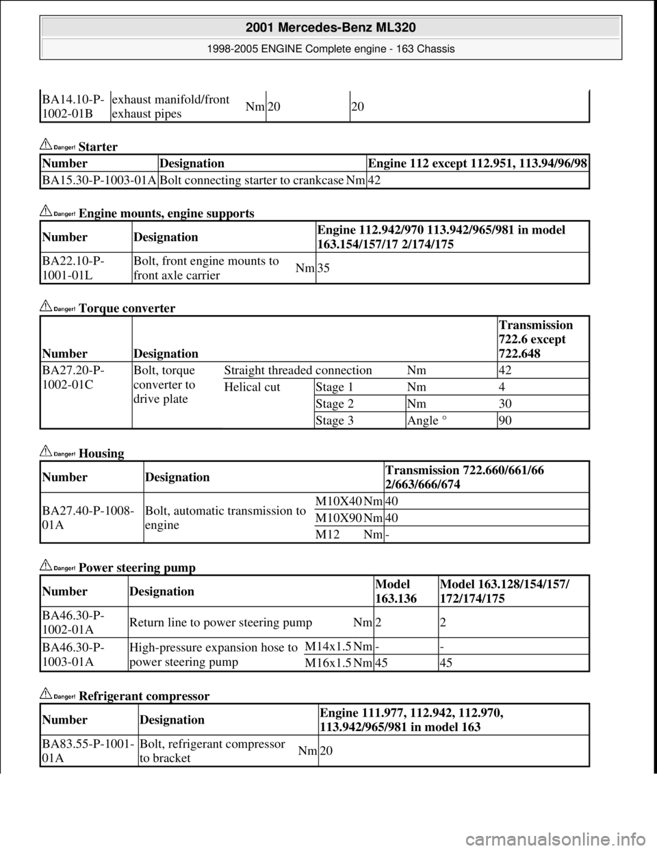
Starter
Engine mounts, engine supports
Torque converter
Housing
Power steering pump
Refrigerant compressor
BA14.10-P-
1002-01Bexhaust manifold/front
exhaust pipesNm2020
NumberDesignationEngine 112 except 112.951, 113.94/96/98
BA15.30-P-1003-01ABolt connecting starter to crankcaseNm42
NumberDesignationEngine 112.942/970 113.942/965/981 in model
163.154/157/17 2/174/175
BA22.10-P-
1001-01LBolt, front engine mounts to
front axle carrierNm35
NumberDesignation
Transmission
722.6 except
722.648
BA27.20-P-
1002-01CBolt, torque
converter to
drive plateStraight threaded connectionNm42
Helical cutStage 1Nm4
Stage 2Nm30
Stage 3Angle °90
NumberDesignationTransmission 722.660/661/66
2/663/666/674
BA27.40-P-1008-
01ABolt, automatic transmission to
engineM10X40Nm40
M10X90Nm40
M12Nm-
NumberDesignationModel
163.136Model 163.128/154/157/
172/174/175
BA46.30-P-
1002-01AReturn line to power steering pumpNm22
BA46.30-P-
1003-01AHigh-pressure expansion hose to
power steering pumpM14x1.5Nm--
M16x1.5Nm4545
NumberDesignationEngine 111.977, 112.942, 112.970,
113.942/965/981 in model 163
BA83.55-P-1001-
01ABolt, refrigerant compressor
to bracketNm20
2001 Mercedes-Benz ML320
1998-2005 ENGINE Complete engine - 163 Chassis
me
Saturday, October 02, 2010 3:17:56 PMPage 59 © 2006 Mitchell Repair Information Company, LLC.
Page 2429 of 4133
Fig. 66: Identifying Sleeve & Pliers
CAULK THREADED INSE RT - AR01.30-P-5440-02B
Fig. 67: Identifying Heli-Coil Repair Set (102 589 00 99 00)
1. Grease caulk drift, screw into installed HELI-COI L insert and tighten with a torque of approx. 25-30
Nm.
2001 Mercedes-Benz ML320
1998-2005 ENGINE Complete engine - 163 Chassis
me
Saturday, October 02, 2010 3:17:56 PMPage 73 © 2006 Mitchell Repair Information Company, LLC.
Page 2436 of 4133
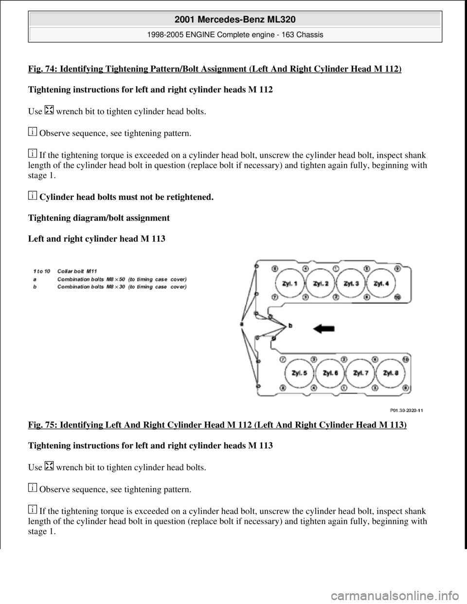
Fig. 74: Identifying Tightening Pattern/Bolt Assignment (Left And Right Cylinder Head M 112)
Tightening instructions for left and right cylinder heads M 112
Use wrench bit to tight en cylinder head bolts.
Observe sequence, see tightening pattern.
If the tightening torque is exceeded on a cylinder he ad bolt, unscrew the cylinder head bolt, inspect shank
length of the cylinder head bolt in question (replace bolt if necessary) and tighten again fully, beginning with
stage 1.
Cylinder head bolts must not be retightened.
Tightening diagram/bolt assignment
Left and right cylinder head M 113
Fig. 75: Identifying Left And Right Cylinder Head M 112 (Left And Right Cylinder Head M 113)
Tightening instructions for left and right cylinder heads M 113
Use wrench bit to tight en cylinder head bolts.
Observe sequence, see tightening pattern.
If the tightening torque is exceeded on a cylinder he ad bolt, unscrew the cylinder head bolt, inspect shank
length of the cylinder head bolt in question (replace bolt if necessary) and tighten again fully, beginning with
stage 1.
2001 Mercedes-Benz ML320
1998-2005 ENGINE Complete engine - 163 Chassis
me
Saturday, October 02, 2010 3:17:56 PMPage 80 © 2006 Mitchell Repair Information Company, LLC.