Page 2444 of 4133

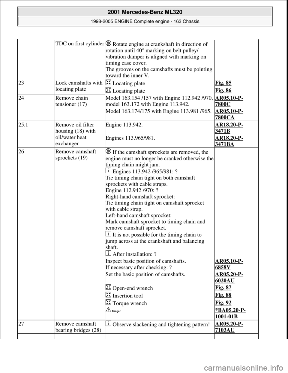
TDC on first cylinder Rotate engine at cra nkshaft in direction of
rotation until 40° marking on belt pulley/
vibration damper is al igned with marking on
timing case cover.
The grooves on the camshafts must be pointing
toward the inner V.
23Lock camshafts with
locating plate Locating plateFig. 85
Locating plateFig. 86
24Remove chain
tensioner (17)Model 163.154 /157 with Engine 112.942 /970,
model 163.172 with Engine 113.942.AR05.10-P-
7800C
Model 163.174/175 with Engine 113.981 /965.AR05.10-P-
7800CA
25.1Remove oil filter
housing (18) with
oil/water heat
exchangerEngine 113.942.AR18.20-P-
3471B
Engines 113.965/981.AR18.20-P-
3471BA
26Remove camshaft
sprockets (19) If the camshaft sprockets are removed, the
engine must no longer be cranked otherwise the
timing chain might jam.
Engines 113.942 /965/981: ?
Tie timing chain tight on both camshaft
sprockets with cable straps.
Engine 112.942 /970: ?
Right-hand camshaft sprocket:
Tie timing chain tight on camshaft sprocket
with cable strap.
Left-hand camshaft sprocket:
Mark camshaft sprocket to timing chain and
remove camshaft sprocket.
It is not possible for the timing chain to
jump across at the crankshaft and balancing
shaft.
After installation: ?
Inspect basic positi on of camshafts.
If necessary after checking: ?AR05.10-P-
6858V
Set the basic position of camshafts.AR05.20-P-
6020AU
Open-end wrenchFig. 87
Insertion toolFig. 88
Torque wrenchFig. 92
*BA05.20-P-
1001-01B
27Remove camshaft
bearing bridges (28) Observe slackening and tightening pattern!AR05.20-P-
7103AU
2001 Mercedes-Benz ML320
1998-2005 ENGINE Complete engine - 163 Chassis
me
Saturday, October 02, 2010 3:17:57 PMPage 88 © 2006 Mitchell Repair Information Company, LLC.
Page 2451 of 4133
Fig. 92: Identifying Torque Wrench (001 589 72 21 00)
Commercially available tools
Repair materials
SCREW DIAGRAM FOR TIMING CASE COVER - AR01.40-P-8000-01B
Assignment of bolts for timing case cover
Apply sealant at the bolts marked (arrows).
NumberDesignation
WH58.30-Z-1001-06A6 mm socket hexagon on flexible shaft for hose clamps with worm drive
WH58.30-Z-1002-06A7 mm socket hexagon on flexible shaft for hose clamps with worm drive
NumberDesignationOrder number
BR00.45-Z-1013-01ASealantA 003 989 98 20
2001 Mercedes-Benz ML320
1998-2005 ENGINE Complete engine - 163 Chassis
me
Saturday, October 02, 2010 3:17:57 PMPage 95 © 2006 Mitchell Repair Information Company, LLC.
Page 2460 of 4133

Engine 113.992 in model 230.474AR14.30-P-
7251RVK
28Separate electrical
line from coolant
temperature
sensor
29Unscrew bolts
(21) of cylinder
head to timing
case cover on
right and left *BA01.40-P-
1002-01C
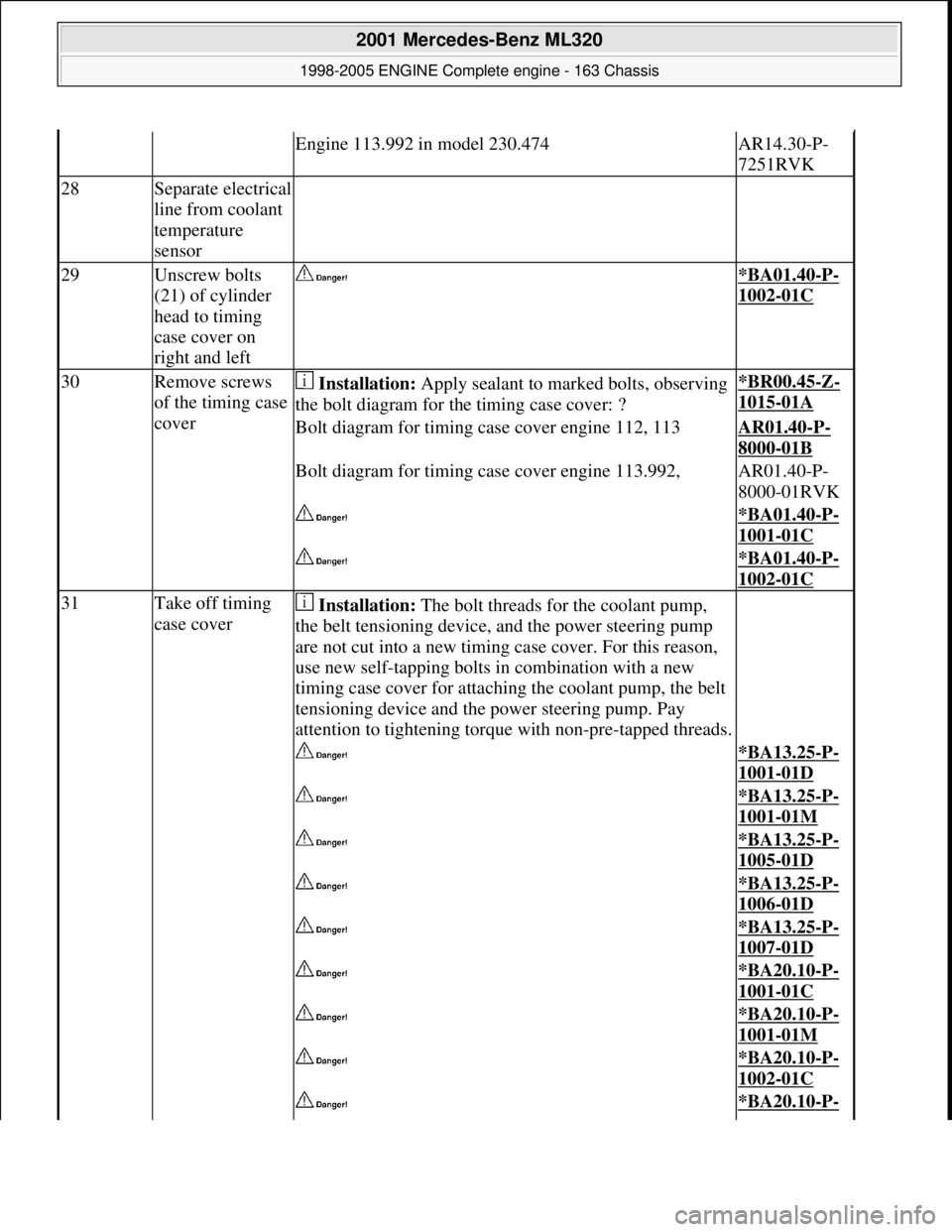
30Remove screws
of the timing case
cover Installation: Apply sealant to marked bolts, observing
the bolt diagram for th e timing case cover: ?*BR00.45-Z-
1015-01A
Bolt diagram for timing case cover engine 112, 113AR01.40-P-
8000-01B
Bolt diagram for timing case cover engine 113.992,AR01.40-P-
8000-01RVK
*BA01.40-P-
1001-01C
*BA01.40-P-
1002-01C
31Take off timing
case cover Installation: The bolt threads for the coolant pump,
the belt tensioning device, and the power steering pump
are not cut into a new timing case cover. For this reason,
use new self-tapping bolts in combination with a new
timing case cover for attaching the coolant pump, the belt
tensioning device and th e power steering pump. Pay
attention to tightening torque with non-pre-tapped threads.
*BA13.25-P-
1001-01D
*BA13.25-P-
1001-01M
*BA13.25-P-
1005-01D
*BA13.25-P-
1006-01D
*BA13.25-P-
1007-01D
*BA20.10-P-
1001-01C
*BA20.10-P-
1001-01M
*BA20.10-P-
1002-01C
*BA20.10-P-
2001 Mercedes-Benz ML320
1998-2005 ENGINE Complete engine - 163 Chassis
me
Saturday, October 02, 2010 3:17:57 PMPage 104 © 2006 Mitchell Repair Information Company, LLC.
Page 2526 of 4133

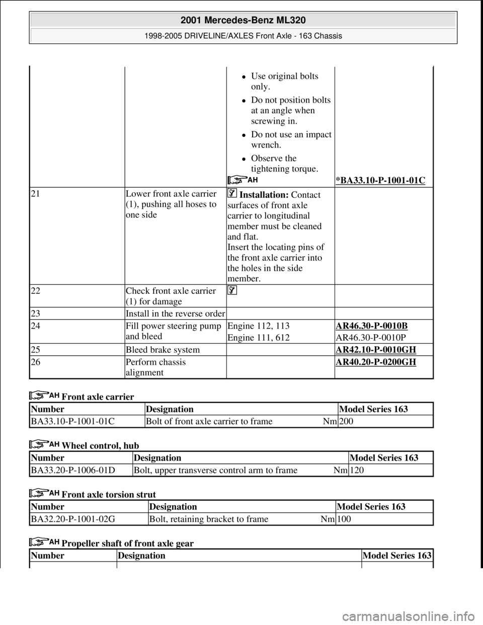
Front axle carrier
Wheel control, hub
Front axle torsion strut
Propeller shaft of front axle gear
Use original bolts
only.
Do not position bolts
at an angle when
screwing in.
Do not use an impact
wrench.
Observe the
tightening torque.
*BA33.10-P-1001-01C
21Lower front axle carrier
(1), pushing all hoses to
one side Installation: Contact
surfaces of front axle
carrier to longitudinal
member must be cleaned
and flat.
Insert the locating pins of
the front axle carrier into
the holes in the side
member.
22Check front axle carrier
(1) for damage
23Install in the reverse order
24Fill power steering pump
and bleedEngine 112, 113AR46.30-P-0010B
Engine 111, 612AR46.30-P-0010P
25Bleed brake system AR42.10-P-0010GH
26Perform chassis
alignment AR40.20-P-0200GH
NumberDesignationModel Series 163
BA33.10-P-1001-01CBolt of front axle carrier to frameNm200
NumberDesignationModel Series 163
BA33.20-P-1006-01DBolt, upper transverse control arm to frameNm120
NumberDesignationModel Series 163
BA32.20-P-1001-02GBolt, retaining bracket to frameNm100
NumberDesignationModel Series 163
2001 Mercedes-Benz ML320
1998-2005 DRIVELINE/AXLES Front Axle - 163 Chassis
me
Saturday, October 02, 2010 3:38:21 PMPage 7 © 2006 Mitchell Repair Information Company, LLC.
Page 2558 of 4133
Fig. 60: Identifying Support (163 589 01 43 00)
Fig. 61: Identifying Press (163 589 03 43 00)
Fig. 62: Identifying Extraction A nd Installation Tool (210 589 03 43 00)
CHECKING FRICTION TORQUE OF TAPE RED ROLLER BEARINGS - AR33.30-P-0470-04GH
Fig. 63: Identifying Connection Piece (100 589 02 59 00)
2001 Mercedes-Benz ML320
1998-2005 DRIVELINE/AXLES Front Axle - 163 Chassis
me
Saturday, October 02, 2010 3:38:22 PMPage 39 © 2006 Mitchell Repair Information Company, LLC.
Page 2559 of 4133
Fig. 64: Identifying Torque Meter (001 589 49 21 00)
Commercially available tools
1. Measure and note friction torque using torque meter (040b) and connecting piece on the hexagon collared
nut.
Fig. 65: Identifying Torque Meter
CHECK FRONT AXLE GEAR OIL LEVEL AND TOP UP IF NECESSARY - AR33.30-P-0525-02GH
Modification notes
Front final-drive unit
Front axle gear
NumberDesignation
WH58.30-Z-1013-06AWrench bit 41 mm hexagon 3/4 inch four-point
8.1.07Filling capacity, Specifications for Operating FluidsModel 163*BF33.30-P-1001-03B
NumberDesignationModel 163
BA33.30-P-1002-03BOil filler screw, front axle gearNm50
BA33.30-P-1003-03BOil drain screw, front axle gearNm50
NumberDesignationModel 163
BF33.30-P-1001-
03BFilling capacityFront axle gearLiters1.2
Specifications for SheetBB00.40-P-0235-
2001 Mercedes-Benz ML320
1998-2005 DRIVELINE/AXLES Front Axle - 163 Chassis
me
Saturday, October 02, 2010 3:38:22 PMPage 40 © 2006 Mitchell Repair Information Company, LLC.
Page 2565 of 4133

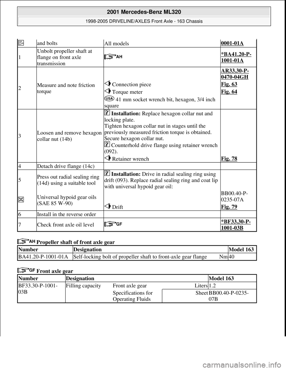
Propeller shaft of front axle gear
Front axle gear
and boltsAll models0001-01A
1
Unbolt propeller shaft at
flange on front axle
transmission
*BA41.20-P-
1001-01A
2Measure and note friction
torque
AR33.30-P-
0470-04GH
Connection pieceFig. 63
Torque meterFig. 64
41 mm socket wrench bit, hexagon, 3/4 inch
square
3Loosen and remove hexagon
collar nut (14b)
Installation: Replace hexagon collar nut and
locking plate.
Tighten hexagon collar nut in stages until the
previously measured friction torque is obtained.
Secure hexagon collar nut.
Counterhold drive flange using retainer wrench
(092).
Retainer wrenchFig. 78
4Detach drive flange (14c)
5Press out radial sealing ring
(14d) using a suitable tool Installation: Drive in radial sealing ring using
drift (093). Replace radial sealing ring and coat lip
with universal hypoid gear oil:
Universal hypoid gear oils
(SAE 85 W-90) BB00.40-P-
0235-07A
DriftFig. 79
6Install in the reverse order
7Check front axle oil level *BF33.30-P-
1001-03B
NumberDesignationModel 163
BA41.20-P-1001-01ASelf-locking bolt of propeller shaft to front-axle gear flangeNm40
NumberDesignationModel 163
BF33.30-P-1001-
03BFilling capacity Front axle gearLiters1.2
Specifications for
Operating FluidsSheetBB00.40-P-0235-
07B
2001 Mercedes-Benz ML320
1998-2005 DRIVELINE/AXLES Front Axle - 163 Chassis
me
Saturday, October 02, 2010 3:38:22 PMPage 46 © 2006 Mitchell Repair Information Company, LLC.
Page 2566 of 4133
Fig. 76: Identifying Connecting Piece (100 589 02 59 00)
Fig. 77: Identifying Torque Meter (001 589 49 21 00)
Fig. 78: Identifying Retainer Wrench (163 589 00 07 00)
Fig. 79: Identifying Drift (163 589 00 15 00)
REMOVE/INSTALL RADIAL SHAFT SEAL AT FRONT AXLE GEAR OF FRONT AXLE SHAFT - AR33.30-P-0545GH
MODEL 163.113 /128 /136 /154 /157 /172 /174 /175
2001 Mercedes-Benz ML320
1998-2005 DRIVELINE/AXLES Front Axle - 163 Chassis
me
Saturday, October 02, 2010 3:38:22 PMPage 47 © 2006 Mitchell Repair Information Company, LLC.