1997 MERCEDES-BENZ ML430 torque
[x] Cancel search: torquePage 2060 of 4133
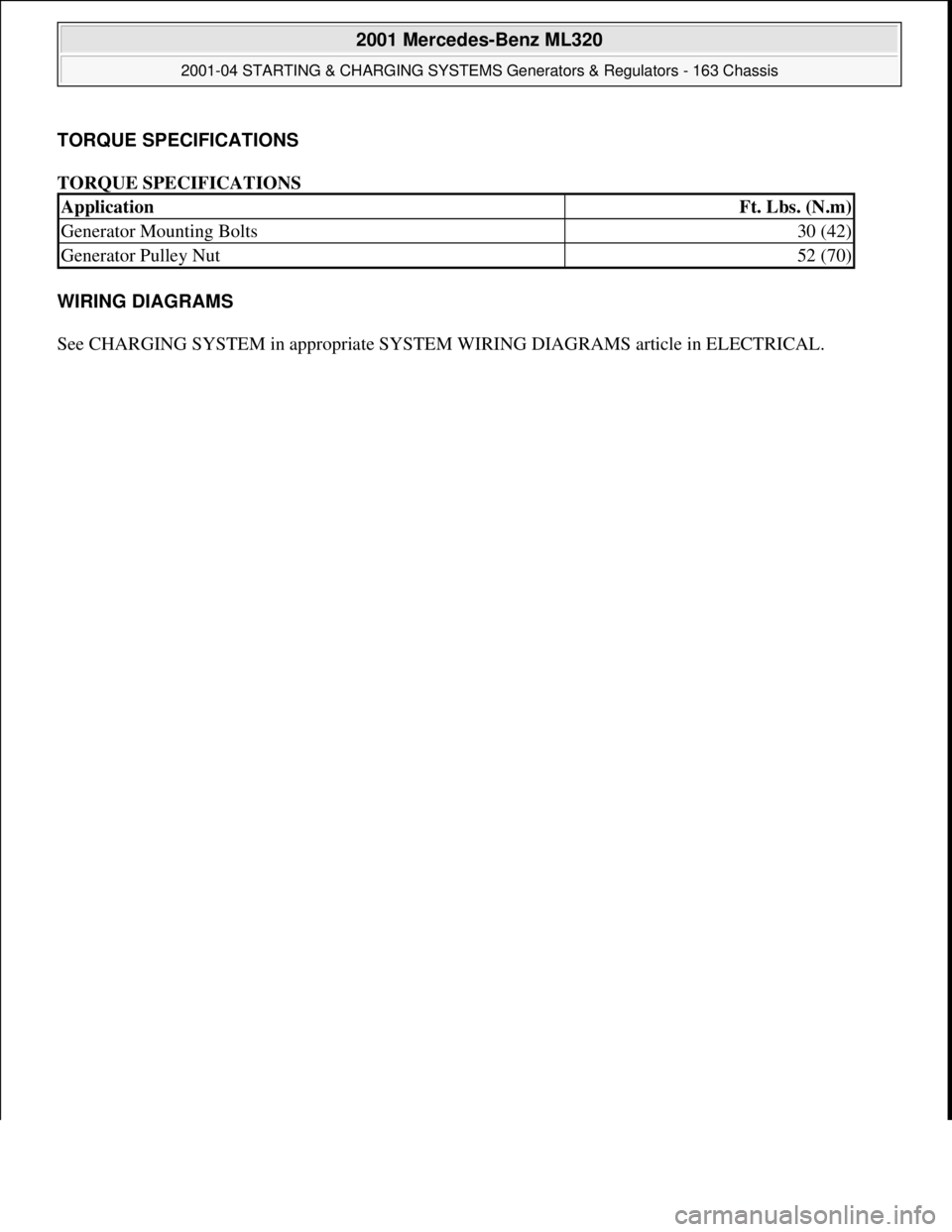
TORQUE SPECIFICATIONS
TORQUE SPECIFICATIONS
WIRING DIAGRAMS
See CHARGING SYSTEM in appropriate SYSTEM WIRING DIAGRAMS article in ELECTRICAL.
ApplicationFt. Lbs. (N.m)
Generator Mounting Bolts30 (42)
Generator Pulley Nut52 (70)
2001 Mercedes-Benz ML320
2001-04 STARTING & CHARGING SYSTEMS Generators & Regulators - 163 Chassis
me
Saturday, October 02, 2010 3:20:32 PMPage 26 © 2006 Mitchell Repair Information Company, LLC.
Page 2088 of 4133

16
Remove poly V-belt (8)
Installation:
Lock tensioning device with
a drift or pin (diameter 5 mm).
Model 163.154 /157 /172.
AR13.22-P-1202B
Model 163.174 /175.
AR13.22-P-1202BA
17
Detach the coolant line (16) at the cylinder
head on the left
6 mm socket hexagon
*WH58.30-Z-1001-06A
7 mm socket hexagon
*WH58.30-Z-1002-06A
18.1
Remove fender liner (9)
Only with engine 113.113.942 /965 / 981.
AR88.10-P-1300GH
19.1
Remove shield (10)
Only with engine 113.942 /965 /981.
20.1
Remove exhaust bracket (11)
Only with engine 113.942 /965 /981.
Support exhaust system.
21
Detach exhaust system at exhaust manifold
Installation:
On vehicles with engine
damage, the exhaust system must be
examined for swarfs before assembling and
any swarfs present must be removed, in order
to avoid consequential damage.
*BA14.10-P-1002-01B
22
Position crankshaft to 40° after ignition TDC
on cylinder 1
The engine must not be turned back;
otherwise the timing chain can get jammed.
AR05.10-P-6858V
Rotate engine at the crankshaft in running
direction until scribe mark 40° on pulley/
vibration damper corresponds with scribe
mark on timing case.
The grooves on the camshafts must be
pointing toward the inner V.
23
Lock camshafts with locating plates
Locating plate
*112589003200
Locating plate
*112589013200
24
Remove chain tensioner (17)
Model 163.154 /157 with engine 112.942/
970, model 163.172 with engine 113.942.
AR05.10-P-7800C
Model 163.174 /175 with engine 113.981/ 965.
AR05.10-P-7800CA
25.1
Remove oil filter housing (18) together with oil-
water heat exchanger
Engine 113.942.
AR18.20-P-3471B
Engine 112.942/970.
AR18.20-P-3471BA
26
Unscrew camshaft sprockets (19)
If camshaft sprockets are removed,
engine must no longer be cranked, otherwise
timing chain might jam.
Engine 113.942 /965 /981:
#
Tie timing chain tight on both camshaft
sprockets with tie straps.
Engine 112.942 /970:
#
Right-hand camshaft sprocket:
Tie timing chain tight on camshaft sprocket
with tie strap.
Left-hand camshaft sprocket:
Mark camshaft sprocket to timing chain and
remove camshaft sprocket.
It is not possible for the timing chain to
jump across at the crankshaft and balancing
shaft.
After installation:
#
Inspect basic position of camshafts.
AR05.10-P-6858V
If necessary after checking:
#
Set the basic position of camshafts
AR05.20-P-6020AU
Open-end wrench
*112589000100
Insertion tool
*112589010300
Torque wrench
*001589722100
*BA05.20-P-1001-01B
27
Remove camshaft bearing bridges (28)
Pay attention to slackening and tightening
pattern!
AR05.20-P-7103AU
28
Unscrew bolts, cylinder head
!
timing case
cover (20)
*BA01.40-P-1002-01C
Copyright DaimlerChrysler AG 20.05.2006 CD-Ausgabe G/10/04 . This WIS print-out will not be recorde
d by Modification services.
Page 4
Page 2092 of 4133
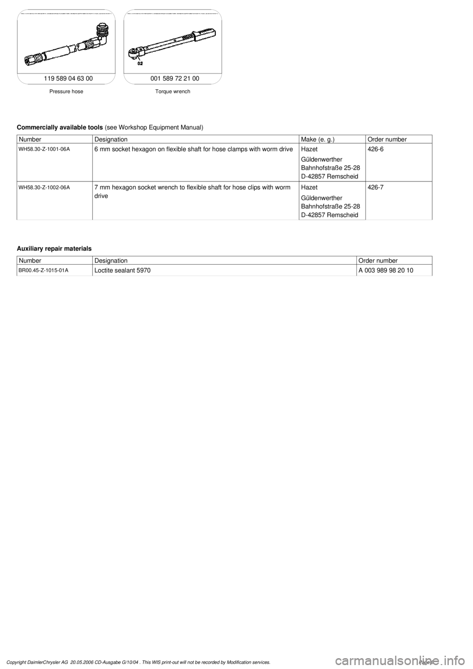
001 589 72 21 00
Torque wrench
Pressure hose
119 589 04 63 00
Commercially available tools
(see Workshop Equipment Manual)
Number
Designation
Make (e. g.)
Order number
WH58.30-Z-1001-06A
6 mm socket hexagon on flexible shaft for hose clamps with worm drive
Hazet
Güldenwerther
Bahnhofstraße 25-28
D-42857 Remscheid
426-6
WH58.30-Z-1002-06A
7 mm hexagon socket wrench to flexible shaft for hose clips with worm
drive
Hazet
Güldenwerther
Bahnhofstraße 25-28
D-42857 Remscheid
426-7
Auxiliary repair materials
Number
Designation
Order number
BR00.45-Z-1015-01A
Loctite sealant 5970A 003 989 98 20 10
Copyright DaimlerChrysler AG 20.05.2006 CD-Ausgabe G/10/04 . This WIS print-out will not be recorde
d by Modification services.
Page 8
Page 2096 of 4133

16
Remove poly V-belt (8)
Installation:
Lock tensioning device with
a drift or pin (diameter 5 mm).
Model 163.154 /157 /172.
AR13.22-P-1202B
Model 163.174 /175.
AR13.22-P-1202BA
17
Detach the coolant line (16) at the cylinder
head on the left
6 mm socket hexagon
*WH58.30-Z-1001-06A
7 mm socket hexagon
*WH58.30-Z-1002-06A
18.1
Remove fender liner (9)
Only with engine 113.113.942 /965 / 981.
AR88.10-P-1300GH
19.1
Remove shield (10)
Only with engine 113.942 /965 /981.
20.1
Remove exhaust bracket (11)
Only with engine 113.942 /965 /981.
Support exhaust system.
21
Detach exhaust system at exhaust manifold
Installation:
On vehicles with engine
damage, the exhaust system must be
examined for swarfs before assembling and
any swarfs present must be removed, in order
to avoid consequential damage.
*BA14.10-P-1002-01B
22
Position crankshaft to 40° after ignition TDC
on cylinder 1
The engine must not be turned back;
otherwise the timing chain can get jammed.
AR05.10-P-6858V
Rotate engine at the crankshaft in running
direction until scribe mark 40° on pulley/
vibration damper corresponds with scribe
mark on timing case.
The grooves on the camshafts must be
pointing toward the inner V.
23
Lock camshafts with locating plates
Locating plate
*112589003200
Locating plate
*112589013200
24
Remove chain tensioner (17)
Model 163.154 /157 with engine 112.942/
970, model 163.172 with engine 113.942.
AR05.10-P-7800C
Model 163.174 /175 with engine 113.981/ 965.
AR05.10-P-7800CA
25.1
Remove oil filter housing (18) together with oil-
water heat exchanger
Engine 113.942.
AR18.20-P-3471B
Engine 112.942/970.
AR18.20-P-3471BA
26
Unscrew camshaft sprockets (19)
If camshaft sprockets are removed,
engine must no longer be cranked, otherwise
timing chain might jam.
Engine 113.942 /965 /981:
#
Tie timing chain tight on both camshaft
sprockets with tie straps.
Engine 112.942 /970:
#
Right-hand camshaft sprocket:
Tie timing chain tight on camshaft sprocket
with tie strap.
Left-hand camshaft sprocket:
Mark camshaft sprocket to timing chain and
remove camshaft sprocket.
It is not possible for the timing chain to
jump across at the crankshaft and balancing
shaft.
After installation:
#
Inspect basic position of camshafts.
AR05.10-P-6858V
If necessary after checking:
#
Set the basic position of camshafts
AR05.20-P-6020AU
Open-end wrench
*112589000100
Insertion tool
*112589010300
Torque wrench
*001589722100
*BA05.20-P-1001-01B
27
Remove camshaft bearing bridges (28)
Pay attention to slackening and tightening
pattern!
AR05.20-P-7103AU
28
Unscrew bolts, cylinder head
!
timing case
cover (20)
*BA01.40-P-1002-01C
Copyright DaimlerChrysler AG 20.05.2006 CD-Ausgabe G/10/04 . This WIS print-out will not be recorde
d by Modification services.
Page 4
Page 2100 of 4133
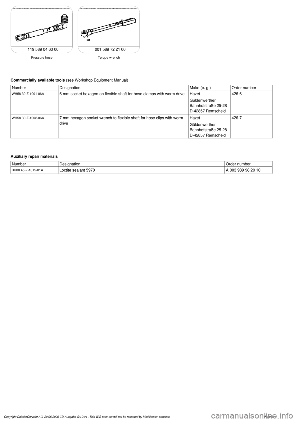
001 589 72 21 00
Torque wrench
Pressure hose
119 589 04 63 00
Commercially available tools
(see Workshop Equipment Manual)
Number
Designation
Make (e. g.)
Order number
WH58.30-Z-1001-06A
6 mm socket hexagon on flexible shaft for hose clamps with worm drive
Hazet
Güldenwerther
Bahnhofstraße 25-28
D-42857 Remscheid
426-6
WH58.30-Z-1002-06A
7 mm hexagon socket wrench to flexible shaft for hose clips with worm
drive
Hazet
Güldenwerther
Bahnhofstraße 25-28
D-42857 Remscheid
426-7
Auxiliary repair materials
Number
Designation
Order number
BR00.45-Z-1015-01A
Loctite sealant 5970A 003 989 98 20 10
Copyright DaimlerChrysler AG 20.05.2006 CD-Ausgabe G/10/04 . This WIS print-out will not be recorde
d by Modification services.
Page 8
Page 2101 of 4133
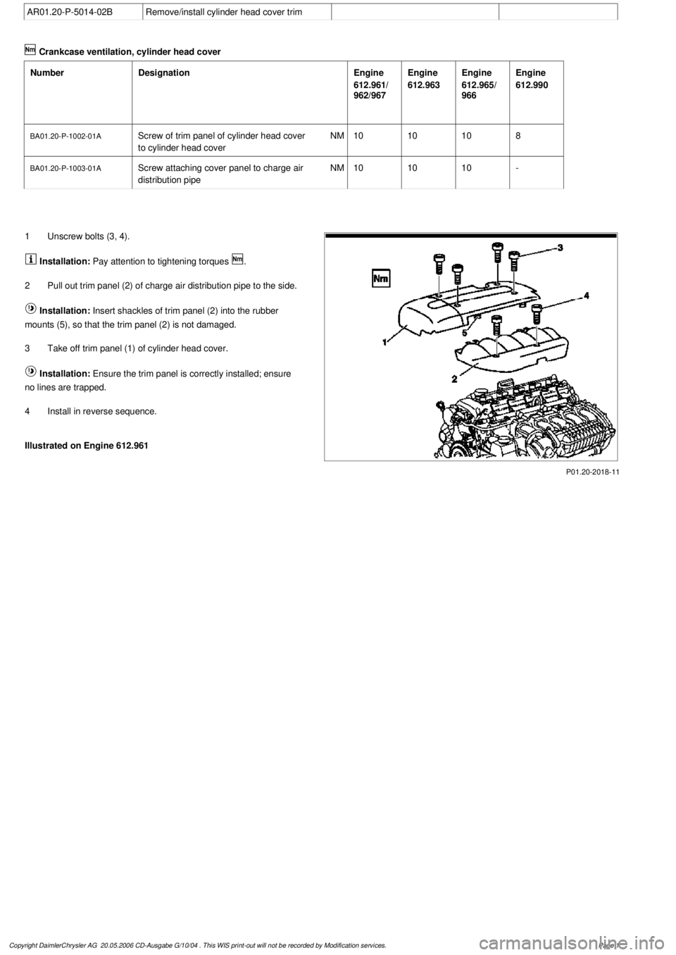
AR01.20-P-5014-02B
Remove/install cylinder head cover trim
Crankcase ventilation, cylinder head cover
Number
Designation
Engine
612.961/
962/967
Engine
612.963
Engine
612.965/
966
Engine
612.990
BA01.20-P-1002-01A
Screw of trim panel of cylinder head cover
to cylinder head cover
NM
101010
8
BA01.20-P-1003-01A
Screw attaching cover panel to charge air
distribution pipe
NM
101010
-
P01.20-2018-11
1
Unscrew bolts (3, 4).
Installation:
Pay attention to tightening torques
.
2
Pull out trim panel (2) of charge air distribution pipe to the side.
Installation:
Insert shackles of trim panel (2) into the rubber
mounts (5), so that the trim panel (2) is not damaged.
3
Take off trim panel (1) of cylinder head cover.
Installation:
Ensure the trim panel is correctly installed; ensure
no lines are trapped.
4
Install in reverse sequence.
Illustrated on Engine 612.961
Copyright DaimlerChrysler AG 20.05.2006 CD-Ausgabe G/10/04 . This WIS print-out will not be recorde
d by Modification services.
Page 1
Page 2171 of 4133
Engine load
Crankshaft position sensor
Camshaft Hall sensor
Coolant temperature sensor
Intake air temperature sensor/charge air.
Coil ignition: The ME control unit interrupts at the point of ignition timing at the ground end the ignition
coil primary circuit of the ignition coil.
ECI ignition system (engine 137): The ME control unit actuates the output stages in the ECI ignition
modules.
The ignition angle can only be checked with the HHT/STAR DIAGNOSIS.
2.Ignition angle adaptation
2.1 Catalytic converter heating-up (warming-up)
The ignition angle is continuously retarded for about 20 seconds in order to more rapidly warm up the catalytic
converter to its operating temperature if:
coolant temperature at start > 15 °C and < 40 °C
Selector lever position P or N
At the same time idle speed is increased by the idle speed control.
2.2 Idle speed
To assist the idle speed control, the ignition angle can be retarded by as much as 36° crank angle or advanced by
as much as 20° crank angle.
Altering the ignition angle provides a more rapid control than altering the position of the throttle valve (idle
speed control).
2.3 Deceleration fuel shutoff
The ignition angle is briefly retarded when combustion is resumed (fuel injectors actuated) in order to prevent a
sudden increase in torque.
2.4 Intake air temperature/coolant temperature
The ignition angle is retarded under load, as a function of the intake air temperature and coolant temperature, in
order to prevent an
y knocking tendency at high intake air and coolant temperatures. The ignition angle is
2001 Mercedes-Benz ML320
1998-2005 ENGINE Electrical System - Engine - 163 Chassis
me
Saturday, October 02, 2010 3:18:54 PMPage 17 © 2006 Mitchell Repair Information Company, LLC.
Page 2172 of 4133
"Retarded" if:
Intake air temperature > 35 °C
Coolant temperature > 105 °C
In supercharged engines the charge air temperature is used as information for the ignition timing adjustment in
place of the intake air temperature.
The values of the retardation of the ignition angle of intake air temperature and coolant temperature are added
together.
2.5 Transmission overload protection
In order to protect the shift elements of the automatic transmission during power shifts (1-2-1, 2-3-2) from
excessive thermal stresses, the ignition angle is briefly retarded during the gearshift and the engine torque
reduced as a result. The ME-SFI control units are supplied with a signal for this purpose from the ETC control
unit (N15/3) over the CAN databus.
2.6 ESP/ASR control mode
In order to reduce the engine torque as rapidly as possible in the ESP/ ASR control mode, the ignition angle is
retarded by the throttle valve actuator (opening angle reduced) prior to the control mode being activated. The
information from the ESP/ASR control unit is supplied over the CAN databus to the ME-SFI control unit.
2.7 Anti-knock control (AKC)
If uncontrolled combustion (knocking) occurs at one or several cylinders, the ignition angle at the relevant
cylinder or cylinders is "Retarded".
2.8 Smooth engine running analysis
To restrain the three way catalytic converter from thermal overload through combustion misfiring and in order
to keep the exhaust emission values, the smooth operation of the engine is continuously monitored.
If combustion misfiring is identified at one or several cylinders, the corresponding fuel injection valves are no
longer actuated after a certain number of misfires.
Engine 104, 111, 112, 113, 119, 120: Smooth operation evaluation is performed through the signals of the
crankshaft position sensor.
Engine 137: Identification of combustion misfiring by means of ionic current signal, see ECI ignition system
function.
2.9 Double ignition engine 112,113,137
2001 Mercedes-Benz ML320
1998-2005 ENGINE Electrical System - Engine - 163 Chassis
me
Saturday, October 02, 2010 3:18:54 PMPage 18 © 2006 Mitchell Repair Information Company, LLC.