Page 1142 of 4133

338 IndexTele Aid* 171
Emergency calls 173
Information 177
Initiating an emergency call
manually 175
Remote door unlock 179
Roadside assistance 175
Stolen vehicle tracking services 180
System self-check 172
Upgrade signals 178
Telematics* 315
Telephone* 170
Temperature
Grades of tires 309
Tires 228
Third row seats* 102
Folding down single seat 102
Installing single seat 104
Removing single seat 104
Storing single seat 103
Tie-down rings (Cargo
compartment) 158Tightening torque 315
Tightening torque (Wheel bolts) 277
Tilt
Head restraint 37, 39
Time
Setting hours 118
Setting minutes 118
Tire inflation pressure
Checking 216, 227
Tire speed rating 198, 315
Tire traction 197
Tires 295, 308
Direction of rotation 227
Driving instructions 196
Retreads 226
Rims and tires 295
Rotating 228
Service life 227
Temperature 228
Temperature grades 309
Tread depth 230
Wear pattern 228
Winter 230Tools 257
Vehicle jack 258
Vehicles with CD-changer* 258
Wheel bolt wrench 258
Tow-away alarm 29, 84
Arming 84
Disarming 84
Disarming for transport 84
Towing
Trailer 206
Towing a trailer 209
Automatic transmission 124
Towing eyes
Front 285
Rear 285
Towing the vehicle 283
Stranded vehicle 286
Tracking services
For stolen vehicle 180
Page 1145 of 4133

341 Index
Wear pattern (tires) 228
Weights 299
Wheel bolt wrench 258
Wheel change
Tightening torque 277
Wheels
Rotating 228
Window curtain airbags 64
Windows see Side windows
Windshield
Defogging 138
Refilling washer fluid 224
Replacing wiper blades 273
Washer fluid 224, 307
Washer system 307
Windshield washer fluid 307
Filler neck 224
Mixing ratio 307
Refilling 224
Wiping with 50Windshield washer system 307
Windshield wipers 49, 129
Intermittent 49
Interval wiping 130
Normal wiper speed 49
Rain sensor* 130
Rear window wiper/washer 51
Replacing wiper blades 273
Simultaneous wiping and washing 51
Single wipe 50
Switching on 49
Wiping with windshield washer
fluid 50
Winter driving
Snow chains 231
Tires 230
Winter driving instructions 198
Winter tires 230Wiper blades
Cleaning 237
Installing 273
Removing 273
Replacing 273
Wiper switch 49
Wiper/washer
Rear window 51
Wiping
And washing simultaneously 50
Intermittent 49, 130
With windshield washer fluid 50
Wiping and washing simultaneously 51
X
Xenon headlamps*
Bi-Xenon* 311
Page 1154 of 4133

closed. The intake air must flow through the whole intake pipe. Its length is selected in such a way that the
pressure waves, produced by the inducting pistons, arrive at the right moment at the open intake valves for the
next induction stroke. The result is improved cylinder charge and thus an increase in torque.
At higher engine speeds (e.g. from 3900 rpm) the actuation to the variable intake manifold switchover valve is
interrupted - the variable flaps open as a result of the spring force. Through the shortened route the pressure
waves arrive in time even at higher rotational speeds before the closing of the intake valves to the combustion
chamber.
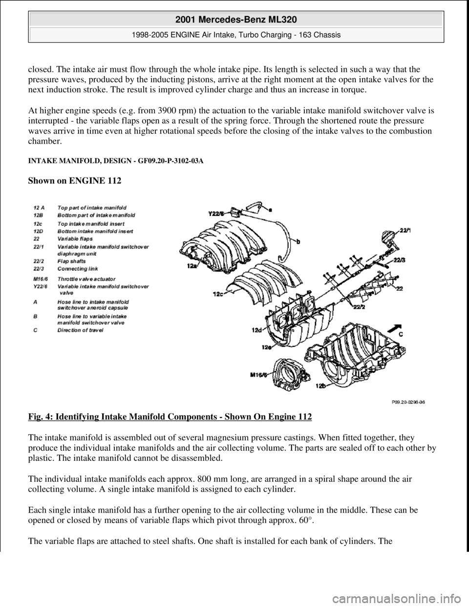
INTAKE MANIFOLD, DESIGN - GF09.20-P-3102-03A
Shown on ENGINE 112
Fig. 4: Identifying Intake Manifold Components
- Shown On Engine 112
The intake manifold is assembled out of several magnesium pressure castings. When fitted together, they
produce the individual intake manifolds and the air collecting volume. The parts are sealed off to each other by
plastic. The intake manifold cannot be disassembled.
The individual intake manifolds each approx. 800 mm long, are arranged in a spiral shape around the air
collecting volume. A single intake manifold is assigned to each cylinder.
Each single intake manifold has a further opening to the air collecting volume in the middle. These can be
opened or closed by means of variable flaps which pivot through approx. 60°.
The variable flaps are attached to steel shafts. One shaft is installed for each bank of c
ylinders. The
2001 Mercedes-Benz ML320
1998-2005 ENGINE Air Intake, Turbo Charging - 163 Chassis
me
Saturday, October 02, 2010 3:16:57 PMPage 3 © 2006 Mitchell Repair Information Company, LLC.
Page 1155 of 4133

interconnected flap shafts are closed by means of vacuum by the intake manifold switchover diaphragm unit.
When the variable intake manifold switchover valve is open, the vacuum is supplied from a vacuum reservoir
with check valve in the intake manifold. The reservoir volume is designed for about 5 operations without
renewed evacuation.
The variable flaps open by means of spring force.
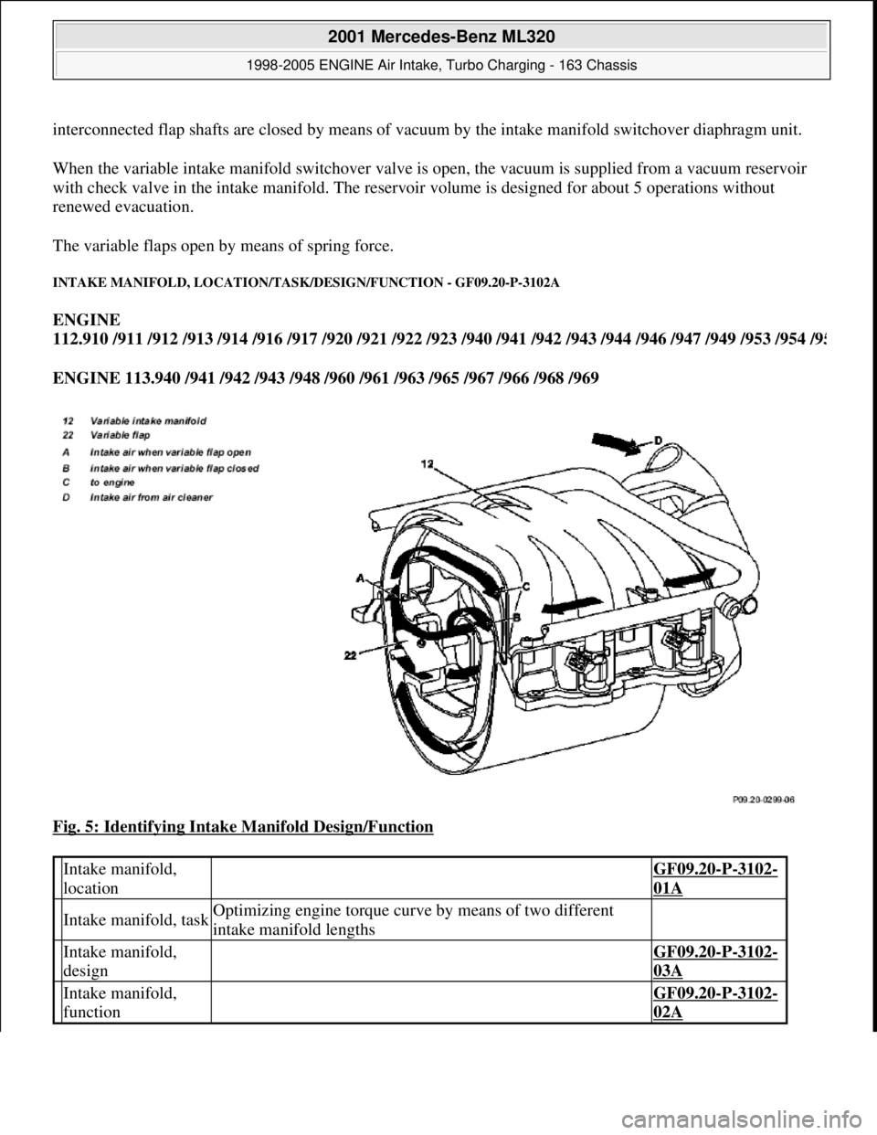
INTAKE MANIFOLD, LOCATION/TASK/DESIGN/FUNCTION - GF09.20-P-3102A
ENGINE
112.910 /911 /912 /913 /914 /916 /917 /920 /921 /922 /923 /940 /941 /942 /943 /944 /946 /947 /949 /953 /954 /9
5
ENGINE 113.940 /941 /942 /943 /948 /960 /961 /963 /965 /967 /966 /968 /969
Fig. 5: Identifying Intake Manifold Design/Function
Intake manifold,
location GF09.20-P-3102-
01A
Intake manifold, taskOptimizing engine torque curve by means of two different
intake manifold lengths
Intake manifold,
design GF09.20-P-3102-
03A
Intake manifold,
function GF09.20-P-3102-
02A
2001 Mercedes-Benz ML320
1998-2005 ENGINE Air Intake, Turbo Charging - 163 Chassis
me
Saturday, October 02, 2010 3:16:57 PMPage 4 © 2006 Mitchell Repair Information Company, LLC.
Page 1172 of 4133

Remove/Install
1 - Remove transmission with torque converter. See REMOVE/INSTALL TRANSMISSION WITH
TORQUE CONVERTER.
2 - Put transmission down on workbench. See Fig. 1
.
3 - Take transmission housing (1) off torque converter housing (2). See Fig. 1
.
4 - Pull torque converter housing (2) off transmission housing (1).
5 - Unscrew internal Torx drive bolts (4a) of oil pump (4).
6 - Screw two opposed bolts (a) into the oil pump housing (4) and press the oil pump (4) out of the
converter housing (2) by applying light blows with a plastic hammer.
Inspect
7 - Check oil pump (4).
8 - Check teflon rings (5a) of multi-disk brake B1 (5), replace if necessary.
9 - Install in the reverse order. NOTE: Internal Torx drive bolts (2a) 15 bolts and internal Torx drive bolts (1a) 2
bolts.
NOTE: The intermediate panel (6) on the torque converter housing (2) can usually
be used several times. The panel must not be coated with sealant.
NOTE: Bolt, transmission housing to converter housing. See Fig. 2
.
NOTE: Ensure that the multi-disk clutch K1 (3) does not fall out.
NOTE: Bolt, oil pump with multi-disk brake B1 to converter housing. See Fig. 2
.
NOTE: According to condition: Dismantle and assemble oil pump. See
DISMANTLING & ASSEMBLING OIL PUMP
.
NOTE: Insert both teflon rings (5a) into groove with grease so that the joint stays
together.
2001 Mercedes-Benz ML320
1998-03 AUTOMATIC TRANSMISSIONS Complete Transmissions - ML 320 - 722.662
me
Saturday, October 02, 2010 3:15:25 PMPage 3 © 2006 Mitchell Repair Information Company, LLC.
Page 1173 of 4133
Fig. 2: Torque Converter Housing Tightening Torques
Courtesy of MERCEDES-BENZ OF NORTH AMERICA.
Dismantling & Assembling Oil Pump
1 - Remove pump gears (22 a nd 23) from pump housing. See Fig. 3.
2 - Check radial seal ring ( 24), replace if necessary.
3 - Replace O-ring (25).
4 - Lubricate pump gears and place in the pump housing. Insert pump gear (22) so that the charger
(arrow) points towards the pump housing.
CAUTION: Use ATF oil.
2001 Mercedes-Benz ML320
1998-03 AUTOMATIC TRANSMI SSIONS Complete Transmissions - ML 320 - 722.662
me
Saturday, October 02, 2010 3:15:25 PMPage 4 © 2006 Mitchell Repair Information Company, LLC.
Page 1175 of 4133
Fig. 3: Dismantling & Assembling Oil Pump
Courtesy of MERCEDES-BENZ OF NORTH AMERICA.
REMOVE/INSTALL TRANSMISSION WITH TORQUE CONVERTER
2001 Mercedes-Benz ML320
1998-03 AUTOMATIC TRANSMISSIONS Complete Transmissions - ML 320 - 722.662
me
Saturday, October 02, 2010 3:15:25 PMPage 6 © 2006 Mitchell Repair Information Company, LLC.
Page 1177 of 4133

Fig. 4: Removing & Installing Transmission With Torque Converter
Courtesy of MERCEDES-BENZ OF NORTH AMERICA.
Remove/Install -
1 - Disconnect ground cable of battery. See DISCONNECT GROUND LEAD FROM BATTERY
.
2 - Remove transfer case. See TRANSFER CASE .
3 - Unbolt oil filler pipe (3) from crankcase. See Fig. 4
.
4 - Remove heat shield (5) and disconnect 13-pin plug connector (2).
5 - Remove locking clips (21) and remove shift.
6 - Unscrew oil drain screw on oil pan (14).
7.1 - Unscrew oil drain screw for torque converter (15).
8.1 - Detach wire for park lock interlock (7) at transmission.
9 - Lambda sensors for primary catalytic converters remove.
10 - Unscrew oil lines (4) to oil cooler from transmission.
11 - Remove cover in oil pan (18) and disconnect torque converter from driven plate at flange.
12 - Unscrew bolts of transmission (19) at crankcase and take out transmission downwards at an angle
using a lifting device. NOTE: Code radio, set clock, normalize power windows and set timer in vehicles
with stationary heater.
NOTE: Adjust shift rod using pliers. See Fig. 10
.
NOTE: If the transmission fluid is burnt or contains wear particles, the oil cooler
lines and oil cooler must be flushed out: Flush oil cooler and oil cooler
lines.
NOTE: Only up to A145272,X708318. For installation and removal, position
selector lever or range selector lever in position "P" and leave in position
"P" when cable/transmission is removed. See REMOVING & INSTALLING
WIRE CABLE/TRANSMISSION FOR PARKING SHIFT LOCK ON
TRANSMISSION.
NOTE: Only up to A145272, X708318.
Upon Installation: Adjust cables for parking shift lock. See ADJUSTING
WIRE CABLES FOR PARKING LOCK INTERLOCK.
NOTE: Upon Installation: Check function of parking shift lock.
2001 Mercedes-Benz ML320
1998-03 AUTOMATIC TRANSMISSIONS Complete Transmissions - ML 320 - 722.662
me
Saturday, October 02, 2010 3:15:25 PMPage 8 © 2006 Mitchell Repair Information Company, LLC.