Page 710 of 4133
243
Tires, Wheels
Te ch n ica l
data
Instruments
and controls Operation Driving
Instrument
cluster display Practical hints
Car care Index
Important!
To realize the total crumple zone in case of a rear end
collision, the space-saver spare wheel must be stored in
its holder with the tire deflated. Properly inflate the tire
prior to mounting it on the axle. See page 249 for
detailed instructions.
When storing the space-saver spare wheel in its holder,
tighten the three wheel bolts with a tightening torque of
37 ft.lb. (50 Nm). Space-saver tire
(except ML 55 AMG)
Removing spare wheel (space-saver tire): 1. Hold left and right side of cover (1) at bottom and pu ll aw ay fr o m b u mpe r ( arr ows ) .
P40.10-2368-26
Page 715 of 4133

248
Tires, Wheels
Te ch n ica l
data
Instruments
and controls Operation Driving
Instrument
cluster display Practical hints
Car care Index
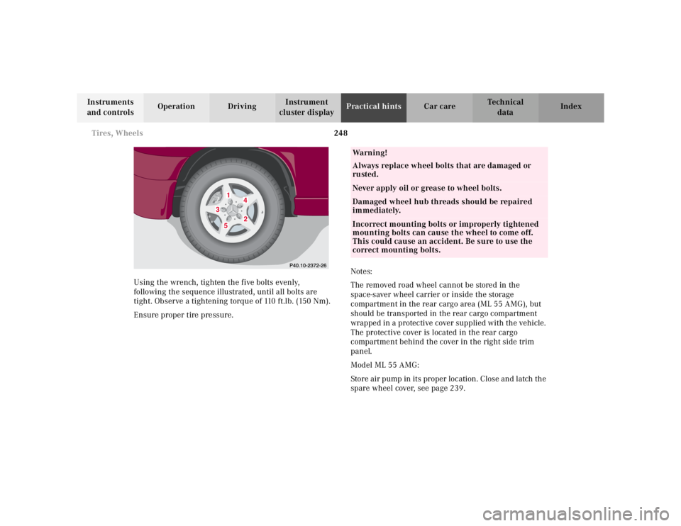
Using the wrench, tighten the five bolts evenly,
following the sequence illustrated, until all bolts are
tight. Observe a tightening torque of 110 ft.lb. (150 Nm).
Ensure proper tire pressure. Notes:
The removed road wheel cannot be stored in the
space-saver wheel carrier or inside the storage
compartment in the rear cargo area (ML 55 AMG), but
should be transported in the rear cargo compartment
wrapped in a protective cover supplied with the vehicle.
The protective cover is located in the rear cargo
compartment behind the cover in the right side trim
panel.
Model ML 55 AMG:
Store air pump in its proper location. Close and latch the
spare wheel cover, see page 239.
1
2
3
4
5
Wa r n i n g !
Always replace wheel bolts that are damaged or
rusted.Never apply oil or grease to wheel bolts.Damaged wheel hub threads should be repaired
immediately.Incorrect mounting bolts or improperly tightened
mounting bolts can cause the wheel to come off.
This could cause an accident. Be sure to use the
correct mounting bolts.
Page 754 of 4133

287
Technical data
Te ch n ica l
data
Instruments
and controls Operation Driving
Instrument
cluster display Practical hints Car care Index
Technical data
Model ML 320 (163 154)
1
ML 430 (163 172)
1
ML 55 AMG (163 174)
1
Engine 112 113 113
Mode of operation 4-stroke engine, gasoline injection 4-stroke engine,
gasoline injection 4-stroke engine,
gasoline injection
No. of cylinders688
Bore 3.54 in (89.90 mm) 3.54 in (89.90 mm) 3.82 in (97.00 mm)
Stroke 3.31 in (84.00 mm) 3.31 in (84.00 mm) 3.62 in (92.00 mm)
Total piston displacement 195.2 cu.in. (3199 cm
3) 260.6 cu.in. (4266 cm
3) 332.0 cu.in. (5439 cm
3)
Compression ratio 10:1 10:1 10.5:1
Output acc. to SAE J 1349 215 hp / 5600 rpm (160 kW / 5600 rpm) 268 hp / 5750 rpm
(200 kW / 5750 rpm) 342 hp / 5500 rpm
(255 kW / 5500 rpm)
Maximum torque acc. to
SAE J 1349 233 ft.lb / 3000 rpm
(315 Nm / 3000 rpm) 288 ft.lb / 3000 rpm
(390 Nm / 3000 rpm) 376 ft.lb / 2800 rpm
( 510 N m / 2 80 0 r p m )
Maximum engine speed 6000 rpm 6000 rpm 6000 rpm
Firing order 1-4-3-6-2-5 1-5-4-2-6-3-7-8 1-5-4-2-6-3-7-8
Poly-V-belt 2390 mm 2390 mm 2390 mm
1 The quoted data apply only to the standard vehicle. See an authorized Mercedes-Benz Light Truck Center for the corresponding d ata of all
special bodies and special equipment.
Page 757 of 4133
290
Technical data
Te ch n ica l
data
Instruments
and controls Operation Driving
Instrument
cluster display Practical hints Car care Index
Electrical system
We i g h t s
(see certification tag)
Model ML 320 ML 430 ML 55 AMG
Generator (alternator) 14 V / 115 A 14 V / 150 A 14 V / 150 A
S t a r te r m o to r 12 V / 1. 7 k W 12V / 1. 7 k W 12V / 1.7 k W
Battery 12V / 100 Ah 12V / 100 Ah 12V / 100 Ah
Spark plugs
Electrode gap
Tightening torque Bosch F 8 DPER
Beru 14 FGH 8 DPUR X 2
0.039 in (1.0 mm)
15–22ft.lb (20–30Nm) Bosch F 8 DPER
Beru 14 FGH 8 DPUR X 2
0.039 in (1.0 mm)
15–22ft.lb (20–30Nm) Bosch F 8 DPER
0.039 in (1.0 mm)
15–22ft.lb (20–30Nm)
Roof load max. 220 lbs (100 kg)
Page 789 of 4133

inspected or replaced. See AIR BAG/SRS COMPONENT INSPECTION & REPLACEMENT TABLES
article in the GENERAL INFORMATION section.
REMOVAL & INSTALLATION
CLOCKSPRING
Information is not available.
CONTROL MODULE
Removal & Installation E
1. Before proceeding, see AIR BAG SAFETY PRECAUTIONS . Turn ignition key to "O" position.
Disable air bag system. See DISABLING & ACTIVATING AIR BAG SYSTEM
.
2. Remove center console. See Fig. 1
. Remove sound deadener. Remove ventilation duct. Disconnect
connectors from control module. Remove cont rol module bolts. Remove control module.
3. To install, reverse removal procedure. Tighten control modul e bolts to specification. See TORQUE
SPECIFICATIONS . Activate air bag system. Program control module. See DIAGNOSTICS.
WARNING:
Accidental air bag deployment is pos sible. Personal injury may result.
Read and follow all WARNINGS and AIR BAG SAFETY PRECAUTIONS
before working on ai r bag system or related components.
2004 Mercedes-Benz ML350
2004 ACCESSORIES/SAFETY EQUIPMENT Merce des-Benz - Air Bag Restraint Systems
me
Saturday, October 02, 2010 3:40:40 PMPage 4 © 2006 Mitchell Repair Information Company, LLC.
Page 791 of 4133
side air bag module electrical connectors. Remove driver-side air bag module. See Fig. 2.
3. To install, reverse removal proc edure. Tighten driver-side air bag module bolts to specification. See
TORQUE SPECIFICATIONS
. Activate air bag system. Read di agnostic codes and erase memory. See
DIAGNOSTICS
.
Fig. 2: Identifying Driver
-side Air Bag Module
Courtesy of MERCEDES-BENZ OF NORTH AMERICA.
EMERGENCY TENSIONING RETRACTOR (ETR)
2004 Mercedes-Benz ML350
2004 ACCESSORIES/SAFETY EQUIPMENT Mercedes-Benz - Air Bag Restraint Systems
me
Saturday, October 02, 2010 3:40:40 PMPage 6 © 2006 Mitchell Repair Information Company, LLC.
Page 792 of 4133

Removal & Installation (Front)
1. Before proceeding, see AIR BAG SAFETY PRECAUTIONS . Disable air bag system. See
DISABLING & ACTIVATI NG AIR BAG SYSTEM
.
2. Move appropriate front seat full y forward. Remove lower trim panel from outer edge of seat cushion
frame. Remove bolt from seat belt end fitting. Remove end fitting from seat cushion. Remove B-pillar
trim panel. Remove bolt from be lt height adjuster. Disconnect ET R electrical connector. Remove ETR
bolts. Remove ETR.
3. To install, reverse removal procedur e. Tighten ETR, seat belt end fitting and belt height adjuster bolts to
specification. See TORQUE SPECIFICATIONS
. Activate air bag system . Read diagnostic codes and
erase memory. See DIAGNOSTICS
.
Removal & Installation (Outer Rear)
1. Before proceeding, see AIR BAG SAFETY PRECAUTIONS . Disable air bag system. See
DISABLING & ACTIVATI NG AIR BAG SYSTEM
.
2. Remove appropriate C-pillar trim panel. Remove bolt from upper seat belt guide bracket. Disconnect
ETR connector. Remove bolts from ETR. Remove ETR.
3. To install, reverse removal proc edure. Tighten ETR bolts and upper seat belt guide bracket bolt to
specification. See TORQUE SPECIFICATIONS
. Activate air bag system Read diagnostic codes and
erase memory. See DIAGNOSTICS
.
HEAD IMPACT AIR BAG MODULE (OUTER REAR)
Removal & Installation
1. Before proceeding, see AIR BAG SAFETY PRECAUTIONS . Disable air bag system. See
DISABLING & ACTIVATI NG AIR BAG SYSTEM
.
2. Remove headliner. See HEADLINER
. Disconnect appropriate head im pact air bag module electrical
connector. Remove screws from rear bracket. Rem ove screws from front and center brackets. Using
Wedge (115-589-03-59-00), remove head impact air ba g module from bracket. Remove head impact air
bag module.
3. To install, reverse removal proce dure. Activate air bag system. Read diagnostic codes and erase memory.
See DIAGNOSTICS
.
HEADLINER
Removal & Installation
1. Before proceeding, see AIR BAG SAFETY PRECAUTIONS . Remove edge trim from sliding/pop-up
roof. Remove front door seals from A- and B-pillars.
2. Remove A-pillar trim panels. Remove front fold ing handle. Remove sun visors and mounting clips.
Remove upper B-pillar trim panels . Remove cargo net holding point c overs. Remove load compartment
handles.
3. Remove coat hooks. Remove C-pill ar trim panels. Remove upper screws from D-pillar trim panels.
Detach rear headliner at roof. Lower headliner until it is supported on front seats. Lower front seat backs
rearward until sufficient ac cess to head impact air ba
g modules is available.
2004 Mercedes-Benz ML350
2004 ACCESSORIES/SAFETY EQUIPMENT Merce des-Benz - Air Bag Restraint Systems
me
Saturday, October 02, 2010 3:40:40 PMPage 7 © 2006 Mitchell Repair Information Company, LLC.
Page 794 of 4133
Fig. 3: Identifying Instrument Panel Components
Courtesy of MERCEDES-BENZ OF NORTH AMERICA.
PASSENGER-SIDE AIR BAG MODULE
Removal & Installation
1. Before proceeding, see AIR BAG SAFETY PRECAUTIONS . Disable air bag system. See
DISABLING & ACTIVATI NG AIR BAG SYSTEM
.
2. Remove instrument panel. See INSTRUMENT PANEL
. Disconnect passenger-side air bag module
electrical connectors. Remove pass enger-side air bag module nuts. Remove passenger-side air bag
module. See Fig. 4
.
3. To install, reverse removal proc edure. Tighten passenger-side air bag module nuts to specification. See
TORQUE SPECIFICATIONS
. Activate air bag system. Read di agnostic codes and erase memory. See
DIAGNOSTICS
.
2004 Mercedes-Benz ML350
2004 ACCESSORIES/SAFETY EQUIPMENT Merce des-Benz - Air Bag Restraint Systems
me
Saturday, October 02, 2010 3:40:40 PMPage 9 © 2006 Mitchell Repair Information Company, LLC.