Page 2241 of 4133

AF80.57-P-6406A
Engine sometimes fails to start and fault message "Start Error" appear in the
instrument cluster
13.8.04
MODEL
163.136 /154 /172 #A as of 145273,
163.136 /154 /172 #X as of 708319,
163.113 /128 /157 /174 /175
Operation no. of operation texts or standard texts and flat rates
Category
Op. no.
Operation text
Time
Acc. no.
Code
P
541011
Perform quick test
004 WU
------
P
805030
Replace drive authorization system (DAS [FBS]) control unit
(after check)
006 WU
------
Damage code
Cause
Remedy
82 801 90
When the ignition is switched on (circuit
15), the engine control unit sends a start
enable request to the DAS [FBS] control unit.
If during this request circuit 15 is switched off
or interrupted before the DAS [FBS] control
unit could respond, the variable code sent the
first time is used again the next time circuit 15
is switched on, since the original request is
saved by the DAS [FBS] control.
1
Replace the DAS [FBS] control unit.
AR54.21-P-1300GH
The fault message "Start Error" appears
in instrument cluster.
When ordering a new control unit, please
specify the chassis number.
Parts ordering notes
Part no.
Designation
Quantity
163 545 07 16
FBS control unit
1
Copyright DaimlerChrysler AG 05.06.2006 CD-Ausgabe G/10/04 . This WIS print-out will not be recorde
d by Modification services.
Page 1
Page 2248 of 4133
marks on the camshafts coincide again.
Fig. 6: Identifying Holes
- Only On Engine 112
Only on engine 112
Checking the balance shaft with engine assembled
Two marks, one at the front of the crankcase and the ot her on the end of the balancing weight, point toward one
anther and can be seen through the left timing case shaft approx. 22 cm. below the parting surface of the
cylinder head cover when the cylinder head cover is removed.
Fig. 7: Identifying Two Mark s On Front Of Crankcase
SAFETY PRECAUTIONS
SAFETY INFORMATION: ENGI NE TIMING - AS05.00-Z-9999ZZ
MODEL all
2004 Mercedes-Benz ML350
1998-2005 ENGINE Engine timing - 163 Chassis
me
Saturday, October 02, 2010 3:39:37 PMPage 7 © 2006 Mitchell Repair Information Company, LLC.
Page 2252 of 4133
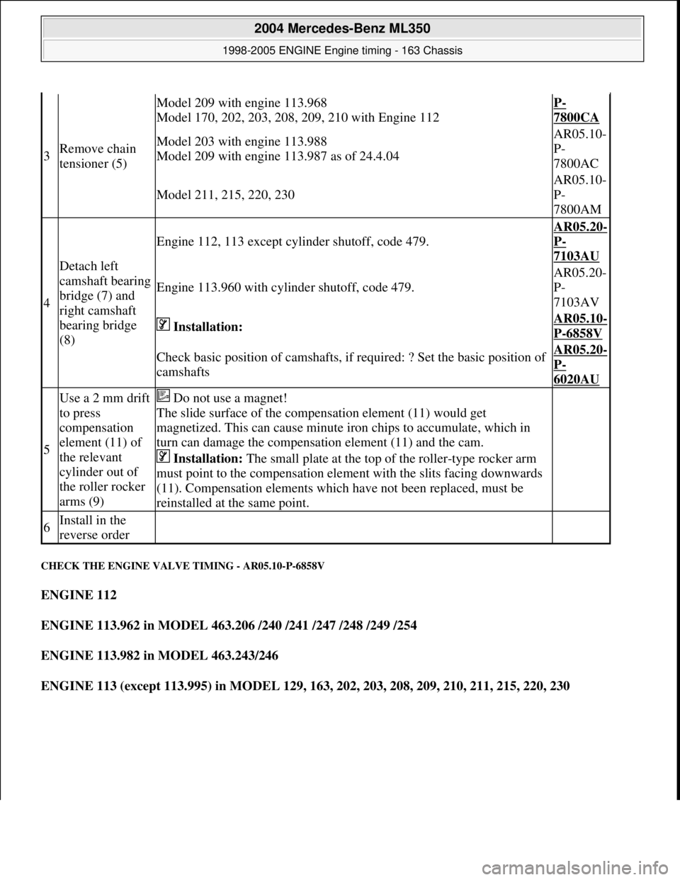
CHECK THE ENGINE VALV E TIMING - AR05.10-P-6858V
ENGINE 112
ENGINE 113.962 in MODEL 463.206 /240 /241 /247 /248 /249 /254
ENGINE 113.982 in MODEL 463.243/246
ENGINE 113 (except 113.995) in MODEL 129, 163, 202, 203, 208, 209, 210, 211, 215, 220, 230
3Remove chain
tensioner (5)
Model 209 with engine 113.968
Model 170, 202, 203, 208, 209, 210 with Engine 112P-
7800CA
Model 203 with engine 113.988
Model 209 with engine 113.987 as of 24.4.04AR05.10-
P-
7800AC
Model 211, 215, 220, 230
AR05.10-
P-
7800AM
4
Detach left
camshaft bearing
bridge (7) and
right camshaft
bearing bridge
(8)
Engine 112, 113 except cylinder shutoff, code 479.
AR05.20-
P-
7103AU
Engine 113.960 with cylinder shutoff, code 479.
AR05.20-
P-
7103AV
Installation: AR05.10-
P-6858V
Check basic position of cam shafts, if required: ? Set the basic position of
camshaftsAR05.20-
P-
6020AU
5
Use a 2 mm drift
to press
compensation
element (11) of
the relevant
cylinder out of
the roller rocker
arms (9) Do not use a magnet!
The slide surface of the compensation element (11) would get
magnetized. This can cause minute iron chips to accumulate, which in
turn can damage the compensati on element (11) and the cam.
Installation: The small plate at the top of the roller-type rocker arm
must point to the compensation element with the slits facing downwards
(11). Compensation elements which have not been replaced, must be
reinstalled at the same point.
6Install in the
reverse order
2004 Mercedes-Benz ML350
1998-2005 ENGINE Engine timing - 163 Chassis
me
Saturday, October 02, 2010 3:39:37 PMPage 11 © 2006 Mitchell Repair Information Company, LLC.
Page 2254 of 4133
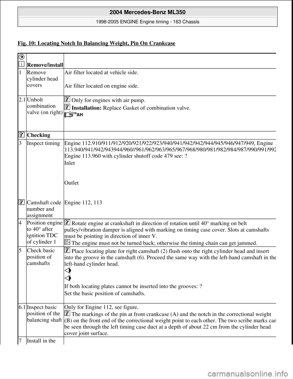
Fig. 10: Locating Notch In Balancing Weight, Pin On Crankcase
Remove/install
1Remove
cylinder head
covers Air filter located
at vehicle side.
Air filter located on engine side.
2.1Unbolt
combination
valve (on right) Only for engines with air pump.
Installation: Replace Gasket of combination valve.
Checking
3Inspect timing Engine 112.910/911/912/920/921/ 922/923/940/941/942/942/944/945/946/947/949, Engine
113.940/941/942/943944/960//961/962/963/965/ 967/968/980/981/982/984/987/990/991/99
2
Engine 113.960 with cylinder shutoff code 479 see: ?
Inlet
Outlet
Camshaft code
number and
assignmentEngine 112, 113
4Position engine
to 40° after
ignition TDC
of cylinder 1 Rotate engine at crankshaft in direct ion of rotation until 40° marking on belt
pulley/vibration damper is aligned with mark ing on timing case cover. Slots at camshafts
must be pointing in di rection of inner V.
The engine must not be turned back; otherwise the timing chain can get jammed.
5Check basic
position of
camshafts Place locating plate for right camshaft (2) fl
ush onto the right cylinder head and insert
into the groove in the camshaft (6). Proceed the same way with the left-hand camshaft in th
e
left-hand cylinder head.
If both locating plates cannot be inserted into the grooves: ?
Set the basic position of camshafts.
6.1Inspect basic
position of the
balancing shaftOnly for Engine 112, see figure.
The markings of the pin at front crankcase (A) and the notch in the correctional weight
(B) on the front end of the corr ectional weight point to each ot her. The two scribe marks ca
n
be seen through the left timing case duct at a depth of about 22 cm from the cylinder head
cover joint surface.
7Install in the
2004 Mercedes-Benz ML350
1998-2005 ENGINE Engine timing - 163 Chassis
me
Saturday, October 02, 2010 3:39:37 PMPage 13 © 2006 Mitchell Repair Information Company, LLC.
Page 2266 of 4133
10. Turn over moving assembly in sert (4) with the digit D5 to the riveting section (arrow).
Fig. 29: Identifying Riveting Tool As sembly Insert & Riveting Section
11. Position riveting tool (2) exactly above the middle of the pins (arrow).
12. Tighten spindle (7)fully at riveting tool (2).
Tightening torque of spindle: Reference value approx. 30 to 35 Nm.
13. Rivet pins of the ri veted link individually.
Fig. 30: Identifying Riveting T ool Exactly Above Middle Of Pins
14. Check riveting (arrows), re-rivet if necessary.
15. Fit on camshaft sprocket (6).
Pay attention to tightening torque of camshaft sprocket.
2004 Mercedes-Benz ML350
1998-2005 ENGINE Engine timing - 163 Chassis
me
Saturday, October 02, 2010 3:39:37 PMPage 25 © 2006 Mitchell Repair Information Company, LLC.
Page 2272 of 4133
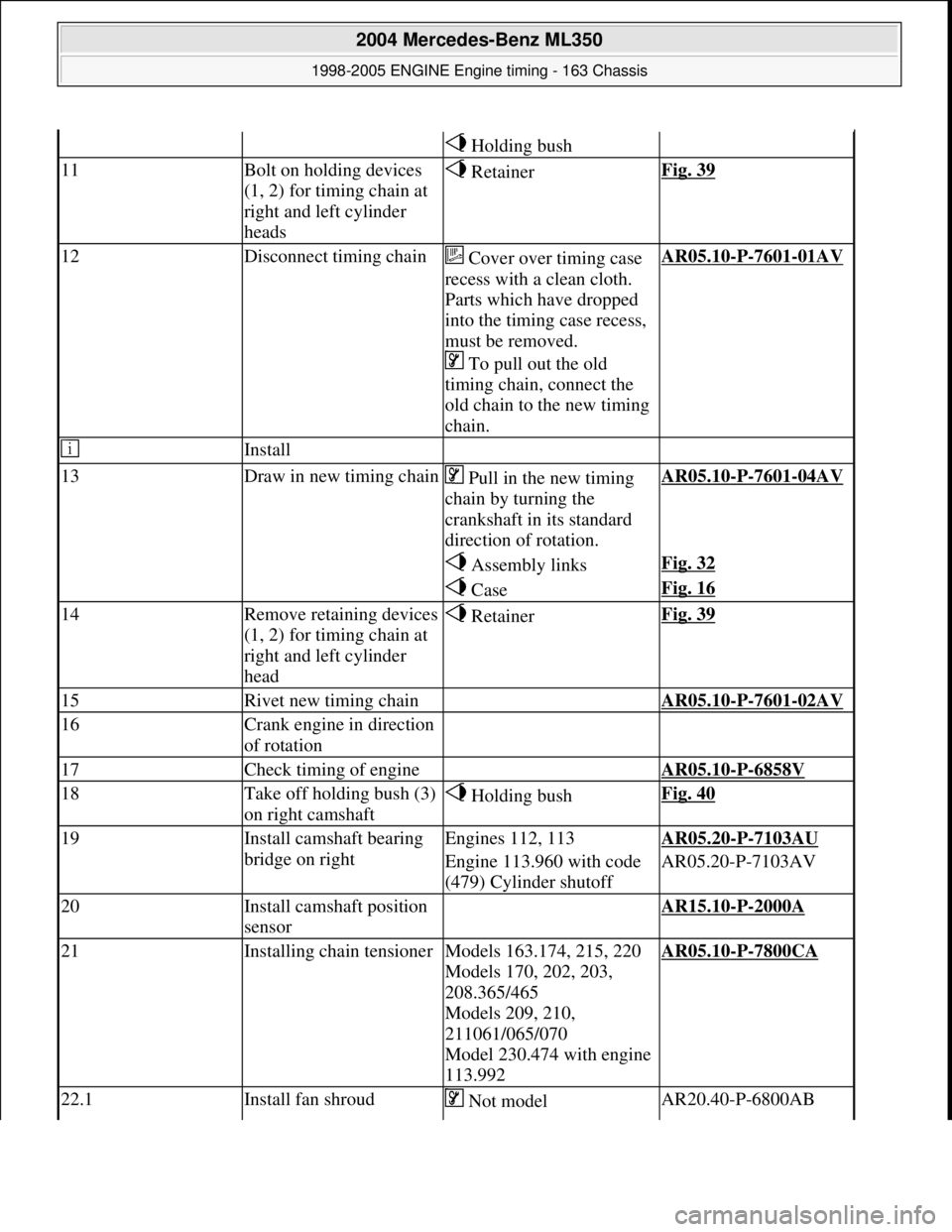
Holding bush
11Bolt on holding devices
(1, 2) for timing chain at
right and left cylinder
heads RetainerFig. 39
12Disconnect timing chain Cover over timing case
recess with a clean cloth.
Parts which have dropped
into the timing case recess,
must be removed.
To pull out the old
timing chain, connect the
old chain to the new timing
chain.AR05.10-P-7601-01AV
Install
13Draw in new timing chain Pull in the new timing
chain by turning the
crankshaft in its standard
direction of rotation.AR05.10-P-7601-04AV
Assembly linksFig. 32
CaseFig. 16
14Remove retaining devices
(1, 2) for timing chain at
right and left cylinder
head RetainerFig. 39
15Rivet new timing chain AR05.10-P-7601-02AV
16Crank engine in direction
of rotation
17Check timing of engine AR05.10-P-6858V
18Take off holding bush (3)
on right camshaft Holding bushFig. 40
19Install camshaft bearing
bridge on rightEngines 112, 113AR05.20-P-7103AU
Engine 113.960 with code
(479) Cylinder shutoffAR05.20-P-7103AV
20Install camshaft position
sensor AR15.10-P-2000A
21Installing chain tensionerModels 163.174, 215, 220
Models 170, 202, 203,
208.365/465
Models 209, 210,
211061/065/070
Model 230.474 with engine
113.992AR05.10-P-7800CA
22.1Install fan shroud Not model AR20.40-P-6800AB
2004 Mercedes-Benz ML350
1998-2005 ENGINE Engine timing - 163 Chassis
me
Saturday, October 02, 2010 3:39:37 PMPage 31 © 2006 Mitchell Repair Information Company, LLC.
Page 2279 of 4133
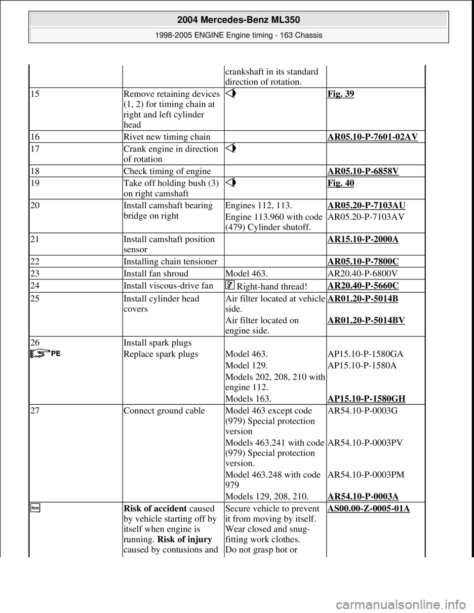
crankshaft in its standard
direction of rotation.
15Remove retaining devices
(1, 2) for timing chain at
right and left cylinder
head Fig. 39
16Rivet new timing chain AR05.10-P-7601-02AV
17Crank engine in direction
of rotation
18Check timing of engine AR05.10-P-6858V
19Take off holding bush (3)
on right camshaft Fig. 40
20Install camshaft bearing
bridge on rightEngines 112, 113.AR05.20-P-7103AU
Engine 113.960 with code
(479) Cylinder shutoff.AR05.20-P-7103AV
21Install camshaft position
sensor AR15.10-P-2000A
22Installing chain tensioner AR05.10-P-7800C
23Install fan shroudModel 463.AR20.40-P-6800V
24Install viscous-drive fan Right-hand thread!AR20.40-P-5660C
25Install cylinder head
coversAir filter locat ed at vehicle
side.AR01.20-P-5014B
Air filter located on
engine side.AR01.20-P-5014BV
26Install spark plugs
Replace spark plugsModel 463.AP15.10-P-1580GA
Model 129.AP15.10-P-1580A
Models 202, 208, 210 with
engine 112.
Models 163.AP15.10-P-1580GH
27Connect ground cableModel 463 except code
(979) Special protection
versionAR54.10-P-0003G
Models 463.241 with code
(979) Special protection
version.AR54.10-P-0003PV
Model 463.248 with code
979AR54.10-P-0003PM
Models 129, 208, 210.AR54.10-P-0003A
Risk of accident caused
by vehicle starting off by
itself when engine is
running. Risk of injury
caused by contusions and Secure vehicle to prevent
it from moving by itself.
Wear closed and snug-
fitting work clothes.
Do not grasp hot or AS00.00-Z-0005-01A
2004 Mercedes-Benz ML350
1998-2005 ENGINE Engine timing - 163 Chassis
me
Saturday, October 02, 2010 3:39:37 PMPage 38 © 2006 Mitchell Repair Information Company, LLC.
Page 2291 of 4133
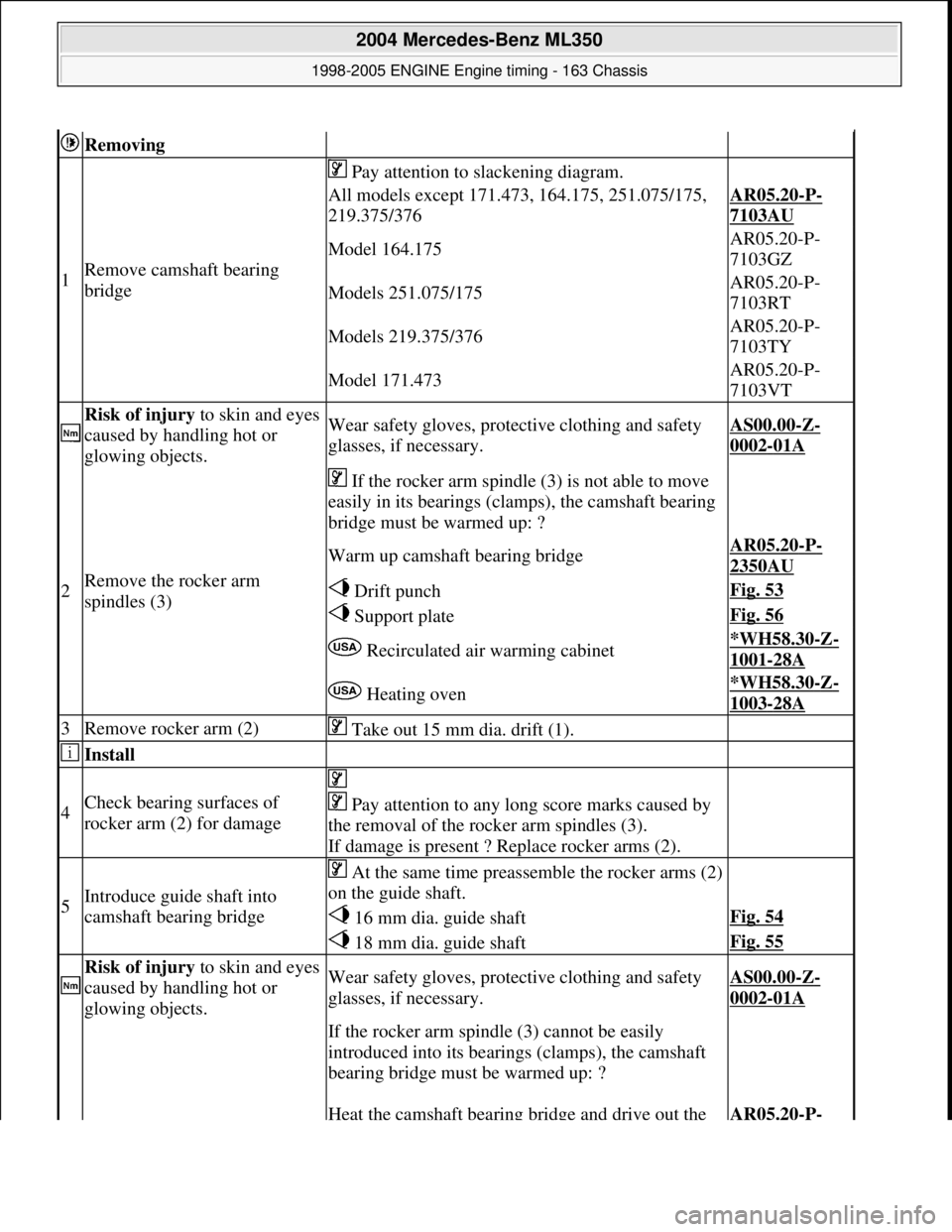
Removing
1Remove camsha ft bearing
bridge
Pay attention to slackening diagram.
All models except 171.473, 164.175, 251.075/175,
219.375/376AR05.20-P-
7103AU
Model 164.175AR05.20-P-
7103GZ
Models 251.075/175AR05.20-P-
7103RT
Models 219.375/376AR05.20-P-
7103TY
Model 171.473AR05.20-P-
7103VT
Risk of injury to skin and eyes
caused by handling hot or
glowing objects.Wear safety gloves, protec tive clothing and safety
glasses, if necessary.AS00.00-Z-
0002-01A
2Remove the rocker arm
spindles (3)
If the rocker arm spindle (3) is not able to move
easily in its bearings (clamps), the camshaft bearing
bridge must be warmed up: ?
Warm up camshaft bearing bridgeAR05.20-P-
2350AU
Drift punchFig. 53
Support plateFig. 56
Recirculated ai r warming cabinet*WH58.30-Z-
1001-28A
Heating oven*WH58.30-Z-
1003-28A
3Remove rocker arm (2) Take out 15 mm dia. drift (1).
Install
4Check bearing surfaces of
rocker arm (2) for damage
Pay attention to any l ong score marks caused by
the removal of the rocker arm spindles (3).
If damage is present ? Replace rocker arms (2).
5Introduce guide shaft into
camshaft bearing bridge
At the same time preassemble the rocker arms (2)
on the guide shaft.
16 mm dia. guide shaftFig. 54
18 mm dia. guide shaftFig. 55
Risk of injury to skin and eyes
caused by handling hot or
glowing objects.Wear safety gloves, protec tive clothing and safety
glasses, if necessary.AS00.00-Z-
0002-01A
If the rocker arm spindle (3) cannot be easily
introduced into its bearings (clamps), the camshaft
bearing bridge must be warmed up: ?
Heat the camshaft bearing bridge and drive out the AR05.20-P-
2004 Mercedes-Benz ML350
1998-2005 ENGINE Engine timing - 163 Chassis
me
Saturday, October 02, 2010 3:39:38 PMPage 50 © 2006 Mitchell Repair Information Company, LLC.