1997 MERCEDES-BENZ ML350 check engine
[x] Cancel search: check enginePage 2037 of 4133

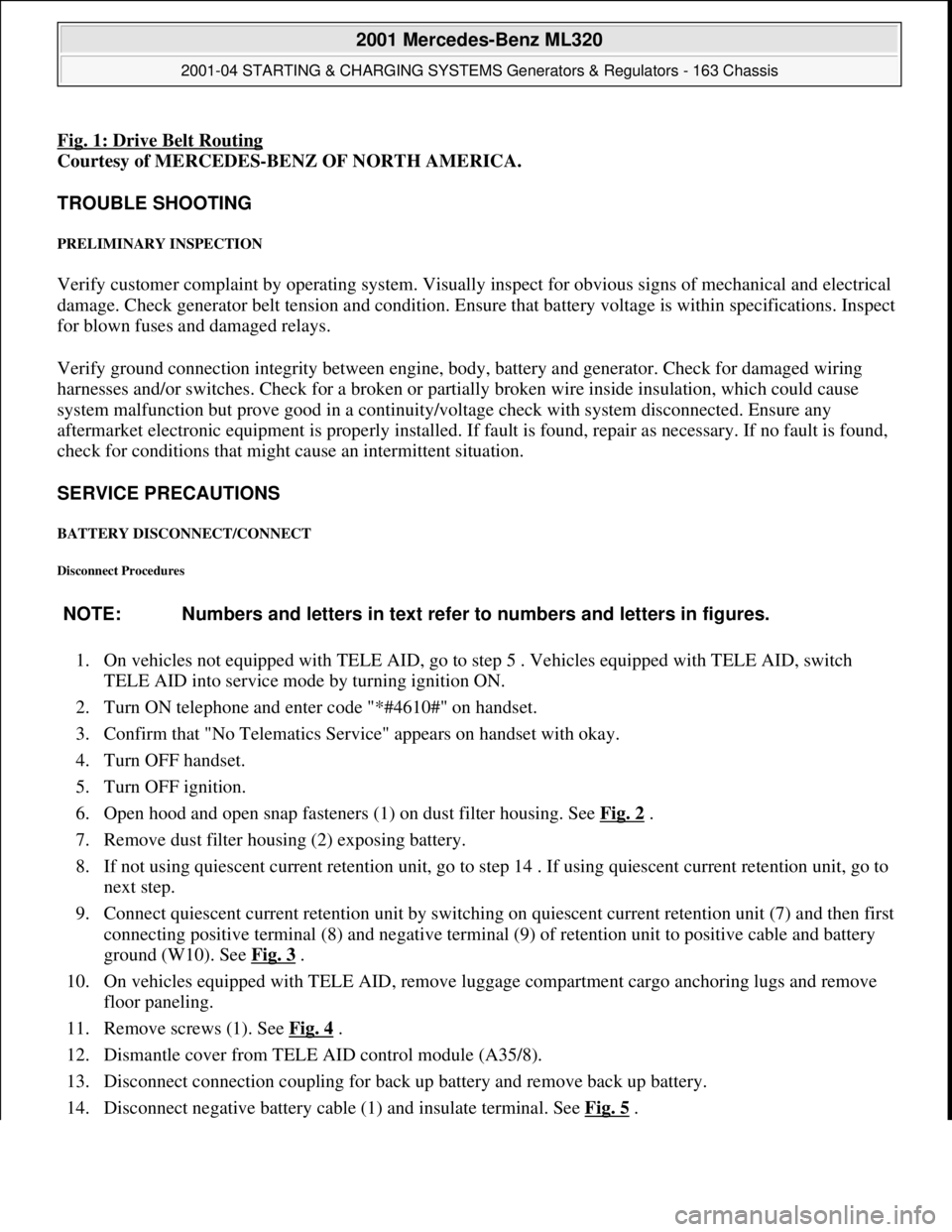
Fig. 1: Drive Belt Routing
Courtesy of MERCEDES-BENZ OF NORTH AMERICA.
TROUBLE SHOOTING
PRELIMINARY INSPECTION
Verify customer complaint by operating system. Visually inspect for obvious signs of mechanical and electrical
damage. Check generator belt tension and condition. Ensure that battery voltage is within specifications. Inspect
for blown fuses and damaged relays.
Verify ground connection integrity between engine, body, battery and generator. Check for damaged wiring
harnesses and/or switches. Check for a broken or partially broken wire inside insulation, which could cause
system malfunction but prove good in a continuity/voltage check with system disconnected. Ensure any
aftermarket electronic equipment is properly installed. If fault is found, repair as necessary. If no fault is found,
check for conditions that might cause an intermittent situation.
SERVICE PRECAUTIONS
BATTERY DISCONNECT/CONNECT
Disconnect Procedures
1. On vehicles not equipped with TELE AID, go to step 5 . Vehicles equipped with TELE AID, switch
TELE AID into service mode by turning ignition ON.
2. Turn ON telephone and enter code "*#4610#" on handset.
3. Confirm that "No Telematics Service" appears on handset with okay.
4. Turn OFF handset.
5. Turn OFF ignition.
6. Open hood and open snap fasteners (1) on dust filter housing. See Fig. 2
.
7. Remove dust filter housing (2) exposing battery.
8. If not using quiescent current retention unit, go to step 14 . If using quiescent current retention unit, go to
next step.
9. Connect quiescent current retention unit by switching on quiescent current retention unit (7) and then first
connecting positive terminal (8) and negative terminal (9) of retention unit to positive cable and battery
ground (W10). See Fig. 3
.
10. On vehicles equipped with TELE AID, remove luggage compartment cargo anchoring lugs and remove
floor paneling.
11. Remove screws (1). See Fig. 4
.
12. Dismantle cover from TELE AID control module (A35/8).
13. Disconnect connection coupling for back up battery and remove back up battery.
14. Disconnect ne
gative battery cable (1) and insulate terminal. See Fig. 5. NOTE: Numbers and letters in text refer to numbers and letters in figures.
2001 Mercedes-Benz ML320
2001-04 STARTING & CHARGING SYSTEMS Generators & Regulators - 163 Chassis
me
Saturday, October 02, 2010 3:20:31 PMPage 3 © 2006 Mitchell Repair Information Company, LLC.
Page 2042 of 4133

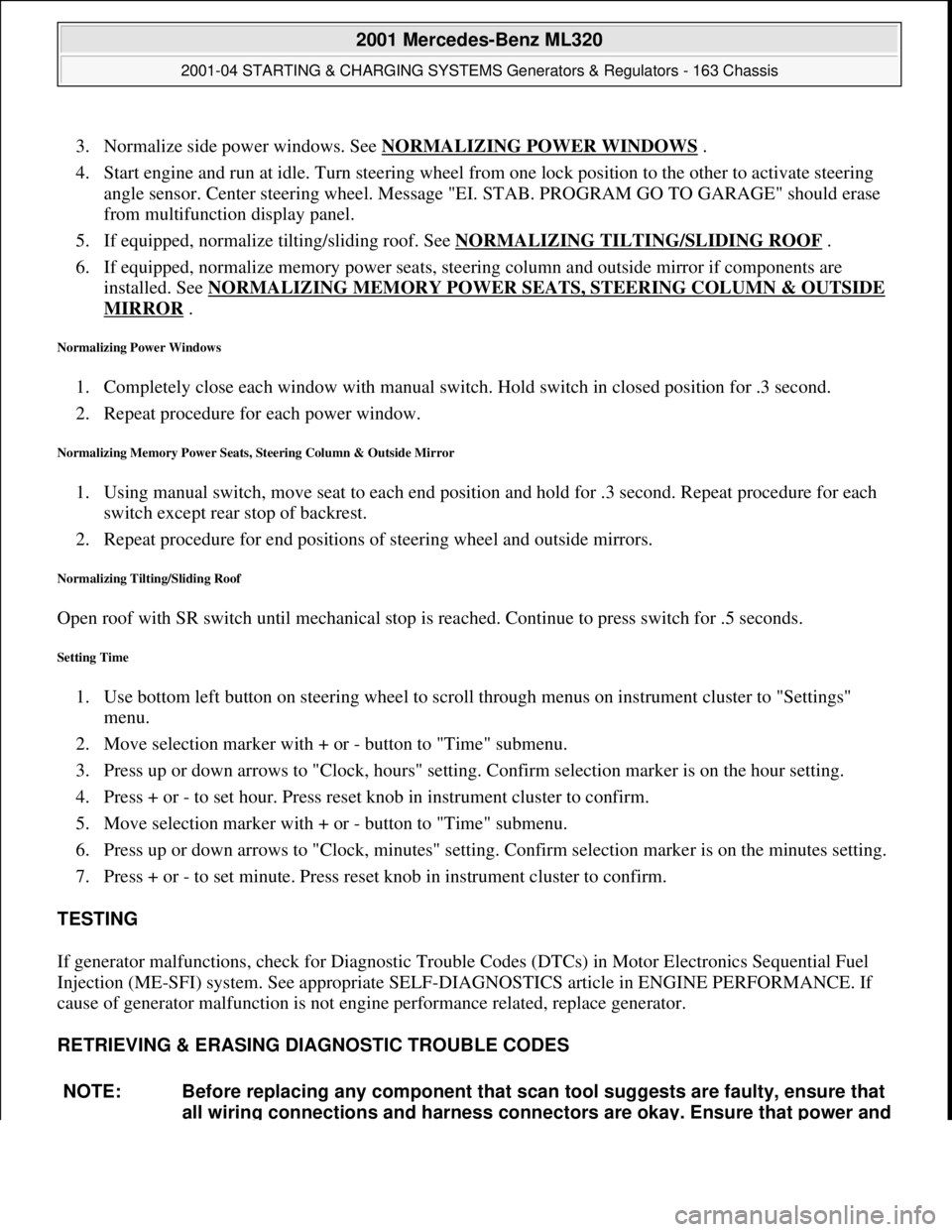
3. Normalize side power windows. See NORMALIZING POWER WINDOWS .
4. Start engine and run at idle. Turn steering wheel from one lock position to the other to activate steering
angle sensor. Center steering wheel. Message "EI. STAB. PROGRAM GO TO GARAGE" should erase
from multifunction display panel.
5. If equipped, normalize tilting/sliding roof. See NORMALIZING TILTING/SLIDING ROOF
.
6. If equipped, normalize memory power seats, steering column and outside mirror if components are
installed. See NORMALIZING MEMORY POWER SEATS, STEERING COLUMN & OUTSIDE
MIRROR .
Normalizing Power Windows
1. Completely close each window with manual switch. Hold switch in closed position for .3 second.
2. Repeat procedure for each power window.
Normalizing Memory Power Seats, Steering Column & Outside Mirror
1. Using manual switch, move seat to each end position and hold for .3 second. Repeat procedure for each
switch except rear stop of backrest.
2. Repeat procedure for end positions of steering wheel and outside mirrors.
Normalizing Tilting/Sliding Roof
Open roof with SR switch until mechanical stop is reached. Continue to press switch for .5 seconds.
Setting Time
1. Use bottom left button on steering wheel to scroll through menus on instrument cluster to "Settings"
menu.
2. Move selection marker with + or - button to "Time" submenu.
3. Press up or down arrows to "Clock, hours" setting. Confirm selection marker is on the hour setting.
4. Press + or - to set hour. Press reset knob in instrument cluster to confirm.
5. Move selection marker with + or - button to "Time" submenu.
6. Press up or down arrows to "Clock, minutes" setting. Confirm selection marker is on the minutes setting.
7. Press + or - to set minute. Press reset knob in instrument cluster to confirm.
TESTING
If generator malfunctions, check for Diagnostic Trouble Codes (DTCs) in Motor Electronics Sequential Fuel
Injection (ME-SFI) system. See appropriate SELF-DIAGNOSTICS article in ENGINE PERFORMANCE. If
cause of generator malfunction is not engine performance related, replace generator.
RETRIEVING & ERASING DIAGNOSTIC TROUBLE CODES
NOTE: Before replacing any component that scan tool suggests are faulty, ensure that
all wiring connections and harness connectors are okay. Ensure that power and
2001 Mercedes-Benz ML320
2001-04 STARTING & CHARGING SYSTEMS Generators & Regulators - 163 Chassis
me
Saturday, October 02, 2010 3:20:32 PMPage 8 © 2006 Mitchell Repair Information Company, LLC.
Page 2048 of 4133

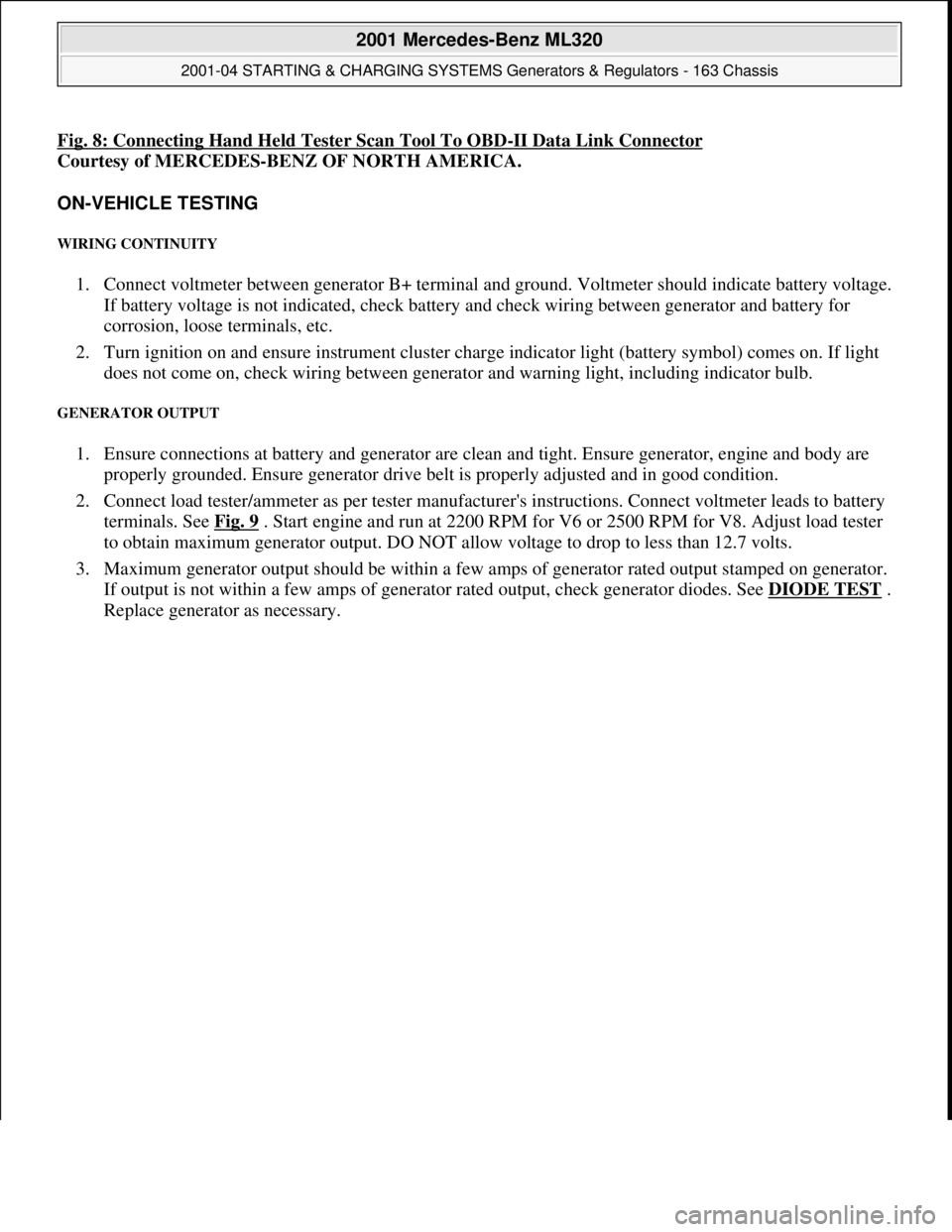
Fig. 8: Connecting Hand Held Tester Scan Tool To OBD-II Data Link Connector
Courtesy of MERCEDES-BENZ OF NORTH AMERICA.
ON-VEHICLE TESTING
WIRING CONTINUITY
1. Connect voltmeter between generator B+ terminal and ground. Voltmeter should indicate battery voltage.
If battery voltage is not indicated, check battery and check wiring between generator and battery for
corrosion, loose terminals, etc.
2. Turn ignition on and ensure instrument cluster charge indicator light (battery symbol) comes on. If light
does not come on, check wiring between generator and warning light, including indicator bulb.
GENERATOR OUTPUT
1. Ensure connections at battery and generator are clean and tight. Ensure generator, engine and body are
properly grounded. Ensure generator drive belt is properly adjusted and in good condition.
2. Connect load tester/ammeter as per tester manufacturer's instructions. Connect voltmeter leads to battery
terminals. See Fig. 9
. Start engine and run at 2200 RPM for V6 or 2500 RPM for V8. Adjust load tester
to obtain maximum generator output. DO NOT allow voltage to drop to less than 12.7 volts.
3. Maximum generator output should be within a few amps of generator rated output stamped on generator.
If output is not within a few amps of generator rated output, check generator diodes. See DIODE TEST
.
Replace
generator as necessary.
2001 Mercedes-Benz ML320
2001-04 STARTING & CHARGING SYSTEMS Generators & Regulators - 163 Chassis
me
Saturday, October 02, 2010 3:20:32 PMPage 14 © 2006 Mitchell Repair Information Company, LLC.
Page 2088 of 4133

16
Remove poly V-belt (8)
Installation:
Lock tensioning device with
a drift or pin (diameter 5 mm).
Model 163.154 /157 /172.
AR13.22-P-1202B
Model 163.174 /175.
AR13.22-P-1202BA
17
Detach the coolant line (16) at the cylinder
head on the left
6 mm socket hexagon
*WH58.30-Z-1001-06A
7 mm socket hexagon
*WH58.30-Z-1002-06A
18.1
Remove fender liner (9)
Only with engine 113.113.942 /965 / 981.
AR88.10-P-1300GH
19.1
Remove shield (10)
Only with engine 113.942 /965 /981.
20.1
Remove exhaust bracket (11)
Only with engine 113.942 /965 /981.
Support exhaust system.
21
Detach exhaust system at exhaust manifold
Installation:
On vehicles with engine
damage, the exhaust system must be
examined for swarfs before assembling and
any swarfs present must be removed, in order
to avoid consequential damage.
*BA14.10-P-1002-01B
22
Position crankshaft to 40° after ignition TDC
on cylinder 1
The engine must not be turned back;
otherwise the timing chain can get jammed.
AR05.10-P-6858V
Rotate engine at the crankshaft in running
direction until scribe mark 40° on pulley/
vibration damper corresponds with scribe
mark on timing case.
The grooves on the camshafts must be
pointing toward the inner V.
23
Lock camshafts with locating plates
Locating plate
*112589003200
Locating plate
*112589013200
24
Remove chain tensioner (17)
Model 163.154 /157 with engine 112.942/
970, model 163.172 with engine 113.942.
AR05.10-P-7800C
Model 163.174 /175 with engine 113.981/ 965.
AR05.10-P-7800CA
25.1
Remove oil filter housing (18) together with oil-
water heat exchanger
Engine 113.942.
AR18.20-P-3471B
Engine 112.942/970.
AR18.20-P-3471BA
26
Unscrew camshaft sprockets (19)
If camshaft sprockets are removed,
engine must no longer be cranked, otherwise
timing chain might jam.
Engine 113.942 /965 /981:
#
Tie timing chain tight on both camshaft
sprockets with tie straps.
Engine 112.942 /970:
#
Right-hand camshaft sprocket:
Tie timing chain tight on camshaft sprocket
with tie strap.
Left-hand camshaft sprocket:
Mark camshaft sprocket to timing chain and
remove camshaft sprocket.
It is not possible for the timing chain to
jump across at the crankshaft and balancing
shaft.
After installation:
#
Inspect basic position of camshafts.
AR05.10-P-6858V
If necessary after checking:
#
Set the basic position of camshafts
AR05.20-P-6020AU
Open-end wrench
*112589000100
Insertion tool
*112589010300
Torque wrench
*001589722100
*BA05.20-P-1001-01B
27
Remove camshaft bearing bridges (28)
Pay attention to slackening and tightening
pattern!
AR05.20-P-7103AU
28
Unscrew bolts, cylinder head
!
timing case
cover (20)
*BA01.40-P-1002-01C
Copyright DaimlerChrysler AG 20.05.2006 CD-Ausgabe G/10/04 . This WIS print-out will not be recorde
d by Modification services.
Page 4
Page 2089 of 4133

29
Slacken cylinder head bolts (21) in stages,
unscrew
Loosen cylinder head bolts according to
loosening schematic only after engine has
cooled down to prevent cylinder head from
distorting.
AR01.30-P-5800-09B
Installation:
Observe tightening pattern
and tightening instructions of cylinder head
bolts.
Oil thread and head contact surface of
cylinder head bolts.
AR01.30-P-5800-07B
Screwdriver insert
*000589031000
Screwdriver insert
*000589041000
*BA01.30-P-1001-01D
30
Remove cylinder head
Installation:
On Engine 112/113 observe
porous points in the left and right cylinder
head. If porous points are present, sealant
must be applied to the cylinder head gasket.
Notes on application of sealant to cylinder
head gasket.
Engine 112, 113
AH01.30-P-1000-04VA
The sealant must be applied within
10 minutes.
Loctite 5900 sealant.
*BR00.45-Z-1015-01A
31
Inspect version of cylinder head gasket
Assignment of cylinder head gasket
Information for assigning the cylinder head
gaskets
Engine 112, 113
AH01.30-P-1000-06V
32
Check cylinder head bolts (21)
AR01.30-P-5800-03B
*BE01.30-P-1001-04B
33
Clean sealing surfaces, inspect for cracks,
shrink holes and flatness, clean threaded
holes.
Pay attention to dowel sleeves (26) for
locating the cylinder head.
Sealing surfaces of crankcase and
cylinder head are provided with an 0.8 mm
thick silicone layer during series production.
At the time of repair installation, silicone
sealant is applied to the sealing area only in
case of any shrink holes.
The sealant must be applied within
10 minutes.
Loctite 5900 sealant.
*BR00.45-Z-1015-01A
34
Install in the reverse order
Danger!
Risk of accident
caused by vehicle starting
off by itself when engine is running.
Risk of
injury
caused by contusions and burns when
working in engine during starting procedure
Secure vehicle to prevent it from moving.
Wear closed and snug-fitting work clothes.
Do not grasp hot or rotating parts.
AS00.00-Z-0005-01A
35
Run engine and inspect for leaks
36
Inspect cooling system for leaks
Warm up engine to operating temperature
and then inspect cooling system or leaks.
AR20.00-P-1010HA
37
Read out and erase fault memory
Stored faults which can result from cables
being disconnected or from simulation during
removal and installation or test work, have to
be processed and erased in the fault
memories after completing the work:
#
Diagnosis Manual Volume 2 Index 0:
Connecting and using test equipment.
Cylinder head/cylinder head bolts
Number
Designation
Engine
112.910/911/912/
913/914/915/
916/917/920/
921/922/923/
940/941/942/
943/944/945/
946/947/949/
951/953/954/
955/960/961/
970/972/973/975
Engine
113.940/941/
942/943/944/
945/946/948/
960/961/962/
963/965/966/
967/968/969/
980/981/982/
984/986/987/
988/990/991/
992/993
BE01.30-P-1001-04B
Cylinder head bolt
Thread diameter
M
1111
Length (L) when new
mm
141.5141.5
Length (L)
mm
T
144.5
T
144.5
Copyright DaimlerChrysler AG 20.05.2006 CD-Ausgabe G/10/04 . This WIS print-out will not be recorde
d by Modification services.
Page 5
Page 2096 of 4133

16
Remove poly V-belt (8)
Installation:
Lock tensioning device with
a drift or pin (diameter 5 mm).
Model 163.154 /157 /172.
AR13.22-P-1202B
Model 163.174 /175.
AR13.22-P-1202BA
17
Detach the coolant line (16) at the cylinder
head on the left
6 mm socket hexagon
*WH58.30-Z-1001-06A
7 mm socket hexagon
*WH58.30-Z-1002-06A
18.1
Remove fender liner (9)
Only with engine 113.113.942 /965 / 981.
AR88.10-P-1300GH
19.1
Remove shield (10)
Only with engine 113.942 /965 /981.
20.1
Remove exhaust bracket (11)
Only with engine 113.942 /965 /981.
Support exhaust system.
21
Detach exhaust system at exhaust manifold
Installation:
On vehicles with engine
damage, the exhaust system must be
examined for swarfs before assembling and
any swarfs present must be removed, in order
to avoid consequential damage.
*BA14.10-P-1002-01B
22
Position crankshaft to 40° after ignition TDC
on cylinder 1
The engine must not be turned back;
otherwise the timing chain can get jammed.
AR05.10-P-6858V
Rotate engine at the crankshaft in running
direction until scribe mark 40° on pulley/
vibration damper corresponds with scribe
mark on timing case.
The grooves on the camshafts must be
pointing toward the inner V.
23
Lock camshafts with locating plates
Locating plate
*112589003200
Locating plate
*112589013200
24
Remove chain tensioner (17)
Model 163.154 /157 with engine 112.942/
970, model 163.172 with engine 113.942.
AR05.10-P-7800C
Model 163.174 /175 with engine 113.981/ 965.
AR05.10-P-7800CA
25.1
Remove oil filter housing (18) together with oil-
water heat exchanger
Engine 113.942.
AR18.20-P-3471B
Engine 112.942/970.
AR18.20-P-3471BA
26
Unscrew camshaft sprockets (19)
If camshaft sprockets are removed,
engine must no longer be cranked, otherwise
timing chain might jam.
Engine 113.942 /965 /981:
#
Tie timing chain tight on both camshaft
sprockets with tie straps.
Engine 112.942 /970:
#
Right-hand camshaft sprocket:
Tie timing chain tight on camshaft sprocket
with tie strap.
Left-hand camshaft sprocket:
Mark camshaft sprocket to timing chain and
remove camshaft sprocket.
It is not possible for the timing chain to
jump across at the crankshaft and balancing
shaft.
After installation:
#
Inspect basic position of camshafts.
AR05.10-P-6858V
If necessary after checking:
#
Set the basic position of camshafts
AR05.20-P-6020AU
Open-end wrench
*112589000100
Insertion tool
*112589010300
Torque wrench
*001589722100
*BA05.20-P-1001-01B
27
Remove camshaft bearing bridges (28)
Pay attention to slackening and tightening
pattern!
AR05.20-P-7103AU
28
Unscrew bolts, cylinder head
!
timing case
cover (20)
*BA01.40-P-1002-01C
Copyright DaimlerChrysler AG 20.05.2006 CD-Ausgabe G/10/04 . This WIS print-out will not be recorde
d by Modification services.
Page 4
Page 2097 of 4133

29
Slacken cylinder head bolts (21) in stages,
unscrew
Loosen cylinder head bolts according to
loosening schematic only after engine has
cooled down to prevent cylinder head from
distorting.
AR01.30-P-5800-09B
Installation:
Observe tightening pattern
and tightening instructions of cylinder head
bolts.
Oil thread and head contact surface of
cylinder head bolts.
AR01.30-P-5800-07B
Screwdriver insert
*000589031000
Screwdriver insert
*000589041000
*BA01.30-P-1001-01D
30
Remove cylinder head
Installation:
On Engine 112/113 observe
porous points in the left and right cylinder
head. If porous points are present, sealant
must be applied to the cylinder head gasket.
Notes on application of sealant to cylinder
head gasket.
Engine 112, 113
AH01.30-P-1000-04VA
The sealant must be applied within
10 minutes.
Loctite 5900 sealant.
*BR00.45-Z-1015-01A
31
Inspect version of cylinder head gasket
Assignment of cylinder head gasket
Information for assigning the cylinder head
gaskets
Engine 112, 113
AH01.30-P-1000-06V
32
Check cylinder head bolts (21)
AR01.30-P-5800-03B
*BE01.30-P-1001-04B
33
Clean sealing surfaces, inspect for cracks,
shrink holes and flatness, clean threaded
holes.
Pay attention to dowel sleeves (26) for
locating the cylinder head.
Sealing surfaces of crankcase and
cylinder head are provided with an 0.8 mm
thick silicone layer during series production.
At the time of repair installation, silicone
sealant is applied to the sealing area only in
case of any shrink holes.
The sealant must be applied within
10 minutes.
Loctite 5900 sealant.
*BR00.45-Z-1015-01A
34
Install in the reverse order
Danger!
Risk of accident
caused by vehicle starting
off by itself when engine is running.
Risk of
injury
caused by contusions and burns when
working in engine during starting procedure
Secure vehicle to prevent it from moving.
Wear closed and snug-fitting work clothes.
Do not grasp hot or rotating parts.
AS00.00-Z-0005-01A
35
Run engine and inspect for leaks
36
Inspect cooling system for leaks
Warm up engine to operating temperature
and then inspect cooling system or leaks.
AR20.00-P-1010HA
37
Read out and erase fault memory
Stored faults which can result from cables
being disconnected or from simulation during
removal and installation or test work, have to
be processed and erased in the fault
memories after completing the work:
#
Diagnosis Manual Volume 2 Index 0:
Connecting and using test equipment.
Cylinder head/cylinder head bolts
Number
Designation
Engine
112.910/911/912/
913/914/915/
916/917/920/
921/922/923/
940/941/942/
943/944/945/
946/947/949/
951/953/954/
955/960/961/
970/972/973/975
Engine
113.940/941/
942/943/944/
945/946/948/
960/961/962/
963/965/966/
967/968/969/
980/981/982/
984/986/987/
988/990/991/
992/993
BE01.30-P-1001-04B
Cylinder head bolt
Thread diameter
M
1111
Length (L) when new
mm
141.5141.5
Length (L)
mm
T
144.5
T
144.5
Copyright DaimlerChrysler AG 20.05.2006 CD-Ausgabe G/10/04 . This WIS print-out will not be recorde
d by Modification services.
Page 5
Page 2156 of 4133

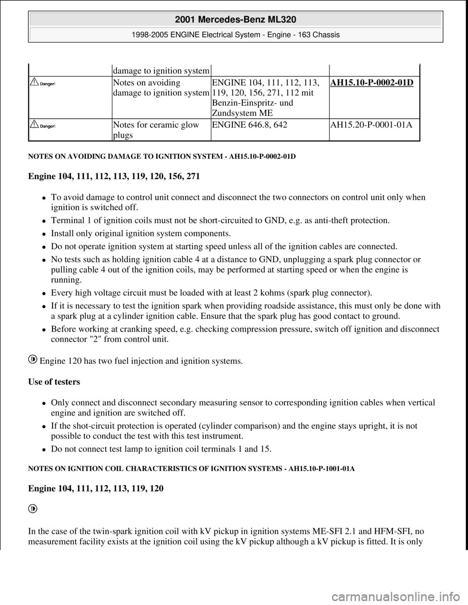
NOTES ON AVOIDING DAMAGE TO IGNITION SYSTEM - AH15.10-P-0002-01D
Engine 104, 111, 112, 113, 119, 120, 156, 271
To avoid damage to control unit connect and disconnect the two connectors on control unit only when
ignition is switched off.
Terminal 1 of ignition coils must not be short-circuited to GND, e.g. as anti-theft protection.
Install only original ignition system components.
Do not operate ignition system at starting speed unless all of the ignition cables are connected.
No tests such as holding ignition cable 4 at a distance to GND, unplugging a spark plug connector or
pulling cable 4 out of the ignition coils, may be performed at starting speed or when the engine is
running.
Every high voltage circuit must be loaded with at least 2 kohms (spark plug connector).
If it is necessary to test the ignition spark when providing roadside assistance, this must only be done with
a spark plug at a cylinder ignition cable. Ensure that the spark plug has good contact to ground.
Before working at cranking speed, e.g. checking compression pressure, switch off ignition and disconnect
connector "2" from control unit.
Engine 120 has two fuel injection and ignition systems.
Use of testers
Only connect and disconnect secondary measuring sensor to corresponding ignition cables when vertical
engine and ignition are switched off.
If the shot-circuit protection is operated (cylinder comparison) and the engine stays upright, it is not
possible to conduct the test with this test instrument.
Do not connect test lamp to ignition coil terminals 1 and 15.
NOTES ON IGNITION COIL CHARACTERISTICS OF IGNITION SYSTEMS - AH15.10-P-1001-01A
Engine 104, 111, 112, 113, 119, 120
In the case of the twin-spark ignition coil with kV pickup in ignition systems ME-SFI 2.1 and HFM-SFI, no
measurement facilit
y exists at the ignition coil using the kV pickup although a kV pickup is fitted. It is only
damage to ignition system
Notes on avoiding
damage to ignition systemENGINE 104, 111, 112, 113,
119, 120, 156, 271, 112 mit
Benzin-Einspritz- und
Zundsystem MEAH15.10-P-0002-01D
Notes for ceramic glow
plugsENGINE 646.8, 642AH15.20-P-0001-01A
2001 Mercedes-Benz ML320
1998-2005 ENGINE Electrical System - Engine - 163 Chassis
me
Saturday, October 02, 2010 3:18:54 PMPage 2 © 2006 Mitchell Repair Information Company, LLC.