Page 1155 of 4133
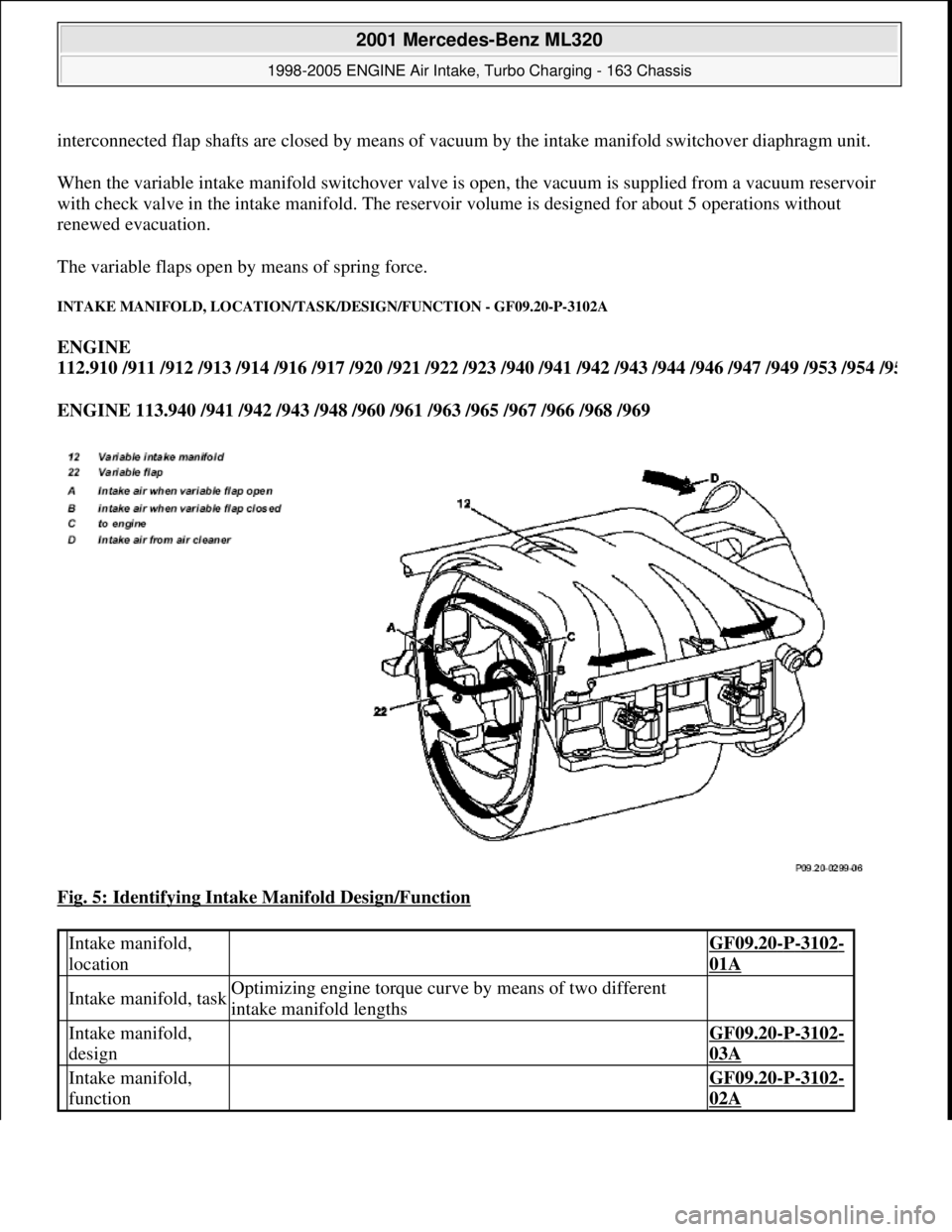
interconnected flap shafts are closed by means of vacuum by the intake manifold switchover diaphragm unit.
When the variable intake manifold switchover valve is open, the vacuum is supplied from a vacuum reservoir
with check valve in the intake manifold. The reservoir volume is designed for about 5 operations without
renewed evacuation.
The variable flaps open by means of spring force.
INTAKE MANIFOLD, LOCATION/TASK/DESIGN/FUNCTION - GF09.20-P-3102A
ENGINE
112.910 /911 /912 /913 /914 /916 /917 /920 /921 /922 /923 /940 /941 /942 /943 /944 /946 /947 /949 /953 /954 /9
5
ENGINE 113.940 /941 /942 /943 /948 /960 /961 /963 /965 /967 /966 /968 /969
Fig. 5: Identifying Intake Manifold Design/Function
Intake manifold,
location GF09.20-P-3102-
01A
Intake manifold, taskOptimizing engine torque curve by means of two different
intake manifold lengths
Intake manifold,
design GF09.20-P-3102-
03A
Intake manifold,
function GF09.20-P-3102-
02A
2001 Mercedes-Benz ML320
1998-2005 ENGINE Air Intake, Turbo Charging - 163 Chassis
me
Saturday, October 02, 2010 3:16:57 PMPage 4 © 2006 Mitchell Repair Information Company, LLC.
Page 1467 of 4133
5 - Detach plug (3) from actuator motor.
6 - Support transmission and remove rear engine crossmember (5) with engine mount.
7 - Slightly lower engine transmission unit.
8 - Support transfer case (2) with lifting device. See SUPPORTING TRANSMISSION WITH
INSPECTION PIT LIFT.
9 - Unscrew bolts (4) and take out transfer case to the back.
10 - Install in the reverse order.
11 - Check filling capacity of transfer case.
Check transfer case (2) for leaks.
Torque Specifications; Driveshaft NOTE: Hang up propeller shaft to one side and ensure that the universal joint is
not damaged.
Self-locking bolt, propeller shaft to transfer case (to front axle). See
Torque Specifications; Driveshaft
.
NOTE:
Engine 112:
Bolt of rear engine crossmember to body.
Engine 112:
Bolt or nut, rear engine mount to transmission.
NOTE: Ensure that no lines are damaged.
NOTE: Transmission plate.
NOTE: Bolt, transfer case to automatic transmission.
Bolt, transfer case to manual transmission.
NOTE: Correct oil level: Bottom edge of filler hole.
Screw plug to transfer case.
DesignationModel 163
Self-locking bolt, front propeller shaft to transfer case (to rear axle)Nm40
2001 Mercedes-Benz ML320
1998-03 AUTOMATIC TRANSMISSIONS Complete Transmissions - ML 320 - 722.662
me
Saturday, October 02, 2010 3:15:30 PMPage 298 © 2006 Mitchell Repair Information Company, LLC.
Page 1819 of 4133
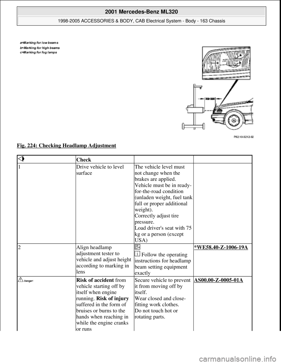
Fig. 224: Checking Headlamp Adjustment
Check
1Drive vehicle to level
surfaceThe vehicle level must
not change when the
brakes are applied.
Vehicle must be in ready-
for-the-road condition
(unladen weight, fuel tank
full or proper additional
weight).
Correctly adjust tire
pressure.
Load driver's seat with 75
kg or a person (except
USA)
2Align headlamp
adjustment tester to
vehicle and adjust height
according to marking in
lens
Follow the operating
instructions for headlamp
beam setting equipment
exactly*WE58.40-Z-1006-19A
Risk of accident from
vehicle starting off by
itself when engine
running. Risk of injury
suffered in the form of
bruises or burns to the
hands when reaching in
while the engine cranks
or runsSecure vehicle to prevent
it from moving off by
itself.
Wear closed and close-
fitting work clothes.
Do not touch hot or
rotating parts.AS00.00-Z-0005-01A
2001 Mercedes-Benz ML320
1998-2005 ACCESSORIES & BODY, CAB Electrical System - Body - 163 Chassis
me
Saturday, October 02, 2010 3:30:10 PMPage 324 © 2006 Mitchell Repair Information Company, LLC.
Page 1820 of 4133
Workshop equipment
WINDSHIELD WASHER - CHECKING AND CORRECTING FLUID LEVEL - AP82.35-P-8210GH
MODEL 163
Windshield washer fluid reservoir
Fig. 225: Locating Windshield Washer Fluid Reservoir
3Run engine and switch on
low beam
4Check headlamp range
control for proper
function(except USA)
The light beams from
both headlamps should
change uniformly
5Set headlamp range
control switch to position
0
6Check low beamsAdjust if necessary
(except USA)
Due to the common
reflector unit, the low
beams, high beams and
fog lamps are adjusted
simultaneously.
US version: ?
See "Owner's Manual"AP82.10-P-8260-01A
7Check high beam
adjustment AP82.10-P-8260-02A
8Check fog lamps AP82.10-P-8260-04A
WE58.40-Z-1006-19AHeadlamp adjustment testing unit
2001 Mercedes-Benz ML320
1998-2005 ACCESSORIES & BODY, CAB Electrical System - Body - 163 Chassis
me
Saturday, October 02, 2010 3:30:10 PMPage 325 © 2006 Mitchell Repair Information Company, LLC.
Page 1901 of 4133
19. Install TrafficStar (1) ra dio and navigation system.
Fig. 334: Identifying GPS Antenna Connector And Sound Connector
CARRYING OUT START-UP AND FU NCTION CHECK - AZ82.61-P-0001-04A
Models 129, 140, 163, 168, 170, 202, 208, 210
System description
Fig. 335: Identifying Trafficstar Display Fi eld, Automatic Button And Mode Button
Step 5 for initial start-up only applies for equipment which has already been installed in a vehicle and on
which initial calibration has been performed.
Start-up step
Entry with TrafficStar
keysFeedback on TrafficStar display field
1Start engine
2Switch on TrafficStarEnter code (see CODE
card) with
multifunction buttons
below the numbers on
the display field.CODE 1 2 3 4 5 6 7 8
3Insert navigation CD
into TrafficStarLoading time approx. 1
min.
2001 Mercedes-Benz ML320
1998-2005 ACCESSORIES & BODY, CAB Electr ical System - Body - 163 Chassis
me
Saturday, October 02, 2010 3:30:12 PMPage 406 © 2006 Mitchell Repair Information Company, LLC.
Page 1964 of 4133
AR61.20-P-1105GH
Remove/install bottom engine compartment paneling
22.6.00
MODEL
163.172 with ENGINE 113.942
MODEL
163.174 with ENGINE 113.981
MODEL
163.175 with ENGINE 113.965
P61.20-2017-12
1
Engine compartment paneling
2
Grub screw
3
Plastic clips
Remove/Install
1
Remove grub screws (2) of plastic clips (3)
6 grub screws pins.
Installation:
Check grub screws, replace
if necessary.
2
Pull out plastic clips (3)
Installation:
Check plastic clips, replace
if necessary.
3
Remove engine compartment panel (1)
Installation:
Ensure that engine
compartment panel is positioned correctly.
4
Install in the reverse order
Copyright DaimlerChrysler AG 20.05.2006 CD-Ausgabe G/10/04 . This WIS print-out will not be recorde
d by Modification services.
Page 1
Page 1970 of 4133
AP82.10-P-8260GH
Check and correct headlamp adjustment
2.7.97
MODEL
163
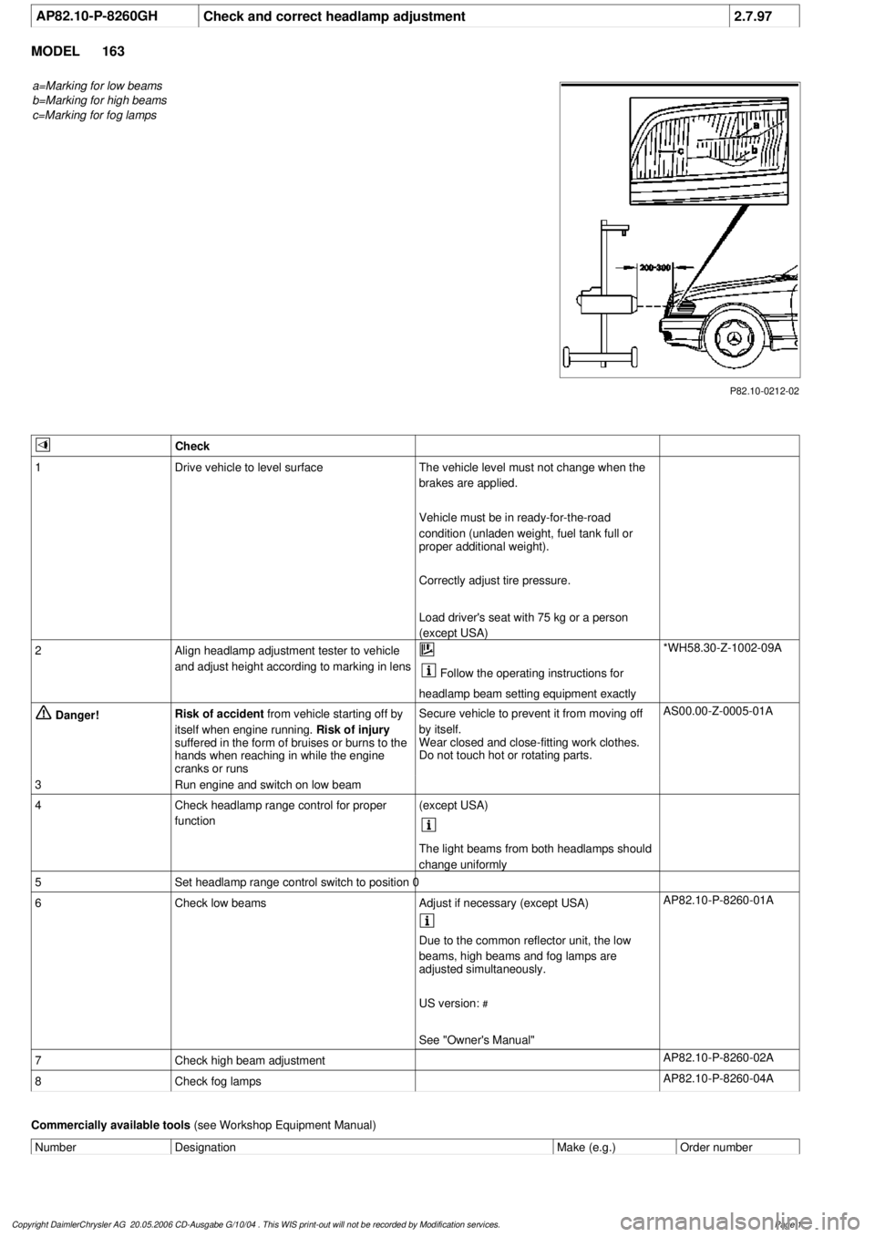
a=Marking for low beams
b=Marking for high beams
c=Marking for fog lamps
P82.10-0212-02
Check
1
Drive vehicle to level surface
The vehicle level must not change when the
brakes are applied.
Vehicle must be in ready-for-the-road
condition (unladen weight, fuel tank full or
proper additional weight).
Correctly adjust tire pressure.
Load driver's seat with 75 kg or a person
(except USA)
2
Align headlamp adjustment tester to vehicle
and adjust height according to marking in lens
Follow the operating instructions for
headlamp beam setting equipment exactly
*WH58.30-Z-1002-09A
Danger!
Risk of accident
from vehicle starting off by
itself when engine running.
Risk of injury
suffered in the form of bruises or burns to the
hands when reaching in while the engine
cranks or runs
Secure vehicle to prevent it from moving off
by itself.
Wear closed and close-fitting work clothes.
Do not touch hot or rotating parts.
AS00.00-Z-0005-01A
3
Run engine and switch on low beam
4
Check headlamp range control for proper
function
(except USA)
The light beams from both headlamps should
change uniformly
5
Set headlamp range control switch to position 0
6
Check low beams
Adjust if necessary (except USA)
AP82.10-P-8260-01A
Due to the common reflector unit, the low
beams, high beams and fog lamps are
adjusted simultaneously.
US version:
#
See "Owner's Manual"
7
Check high beam adjustment
AP82.10-P-8260-02A
8
Check fog lamps
AP82.10-P-8260-04A
Commercially available tools
(see Workshop Equipment Manual)
Number
Designation
Make (e.g.)
Order number
Copyright DaimlerChrysler AG 20.05.2006 CD-Ausgabe G/10/04 . This WIS print-out will not be recorde
d by Modification services.
Page 1
Page 2034 of 4133
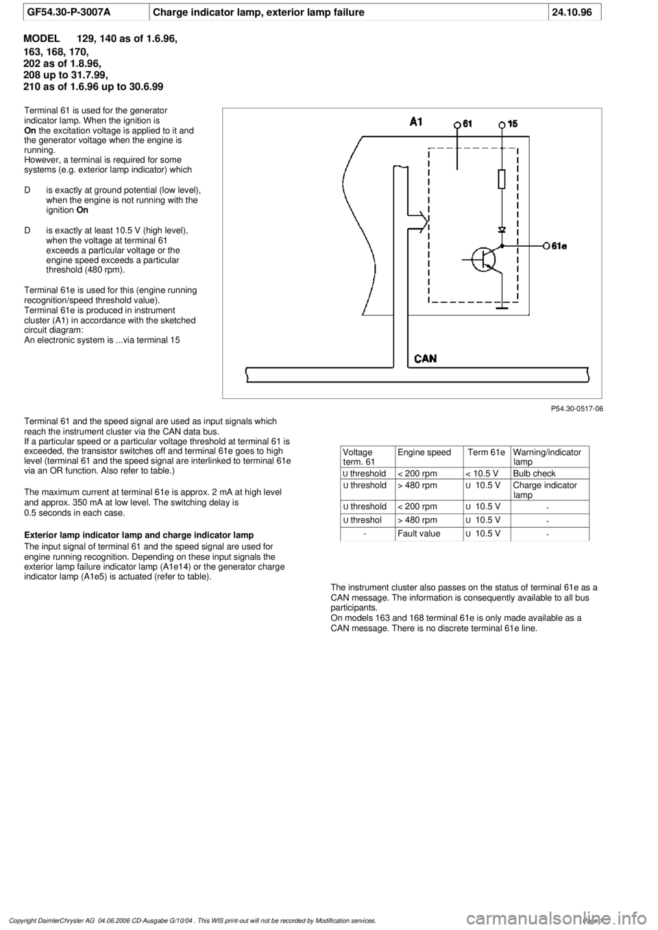
GF54.30-P-3007A
Charge indicator lamp, exterior lamp failure
24.10.96
MODEL
129, 140 as of 1.6.96,
163, 168, 170,
202 as of 1.8.96,
208 up to 31.7.99,
210 as of 1.6.96 up to 30.6.99
P54.30-0517-06
Terminal 61 is used for the generator
indicator lamp. When the ignition is
On
the excitation voltage is applied to it and
the generator voltage when the engine is
running.
However, a terminal is required for some
systems (e.g. exterior lamp indicator) which
D
is exactly at ground potential (low level),
when the engine is not running with the
ignition
On
D
is exactly at least 10.5 V (high level),
when the voltage at terminal 61
exceeds a particular voltage or the
engine speed exceeds a particular
threshold (480 rpm).
Terminal 61e is used for this (engine running
recognition/speed threshold value).
Terminal 61e is produced in instrument
cluster (A1) in accordance with the sketched
circuit diagram:
An electronic system is ...via terminal 15
Terminal 61 and the speed signal are used as input signals which
reach the instrument cluster via the CAN data bus.
If a particular speed or a particular voltage threshold at terminal 61 is
exceeded, the transistor switches off and terminal 61e goes to high
level (terminal 61 and the speed signal are interlinked to terminal 61e
via an OR function. Also refer to table.)
The maximum current at terminal 61e is approx. 2 mA at high level
and approx. 350 mA at low level. The switching delay is
0.5 seconds in each case.
Exterior lamp indicator lamp and charge indicator lamp
The input signal of terminal 61 and the speed signal are used for
engine running recognition. Depending on these input signals the
exterior lamp failure indicator lamp (A1e14) or the generator charge
indicator lamp (A1e5) is actuated (refer to table).
The instrument cluster also passes on the status of terminal 61e as a
CAN message. The information is consequently available to all bus
participants.
On models 163 and 168 terminal 61e is only made available as a
CAN message. There is no discrete terminal 61e line.
Voltage
term. 61
Engine speed
Term 61e
Warning/indicator
lamp
U
threshold
< 200 rpm
< 10.5 V
Bulb check
U
threshold
> 480 rpm
U
10.5 V
Charge indicator
lamp
U
threshold
< 200 rpm
U
10.5 V
-
U
threshol
> 480 rpm
U
10.5 V
-
-
Fault value
U
10.5 V
-
Copyright DaimlerChrysler AG 04.06.2006 CD-Ausgabe G/10/04 . This WIS print-out will not be recorde
d by Modification services.
Page 1