1997 MERCEDES-BENZ ML350 check engine
[x] Cancel search: check enginePage 3872 of 4133
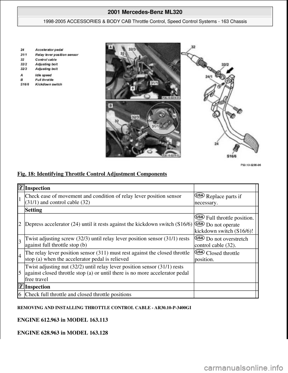
Fig. 18: Identifying Throttle Control Adjustment Components
REMOVING AND INSTALLING THROTTLE CONTROL CABLE - AR30.10-P-3400GI
ENGINE 612.963 in MODEL 163.113
ENGINE 628.963 in MODEL 163.128
Inspection
1Check ease of movement and condition of relay lever position sensor
(31/1) and control cable (32) Replace parts if
necessary.
Setting
2Depress accelerator (24) until it rests against the kickdown switch (S16/6)
Full throttle position.
Do not operate
kickdown switch (S16/6)!
3Twist adjusting screw (32/3) until relay lever position sensor (31/1) rests
against full throttle stop (b) Do not overstretch
control cable (32).
4The relay lever position sensor (311) must rest against the closed throttle
stop (a) when the accelerator pedal is relieved Closed throttle
position.
5
Twist adjusting nut (32/2) until relay lever position sensor (31/1) rests
against closed throttle stop (a) or until there is no more accelerator pedal
free travel
Inspection
6Check full throttle and closed throttle positions
2001 Mercedes-Benz ML320
1998-2005 ACCESSORIES & BODY CAB Throttle Control, Speed Control Systems - 163 Chassis
me
Saturday, October 02, 2010 3:36:28 PMPage 32 © 2006 Mitchell Repair Information Company, LLC.
Page 3874 of 4133
REMOVING AND INSTALLING ACCELERATOR PEDAL - AR30.12-P-1321GH
ENGINE 111.977 in MODEL 163.136
ENGINE 112.942 in MODEL 163.154
ENGINE 112.970 in MODEL 163.157
ENGINE 113.981 in MODEL 163.174
6Push control cable (32) from vehicle interior
towards the outside Do not push rubber grommet out
of splash wall.
7Remove entire control cable (32) from engine
compartment
8Install in the reverse order
9Check throttle control, adjust
Engine 112.942/970,
113.942/965/981 ?
Automatic transmissionAR30.10-P-
1010GJ
Engine 612.963: ?
Manual/automatic transmissionAR30.10-P-
1010GH
Engine 628.963: ?
Automatic transmissionAR30.10-P-
1010GH
2001 Mercedes-Benz ML320
1998-2005 ACCESSORIES & BODY CAB Throttle Control, Speed Control Systems - 163 Chassis
me
Saturday, October 02, 2010 3:36:28 PMPage 34 © 2006 Mitchell Repair Information Company, LLC.
Page 3876 of 4133
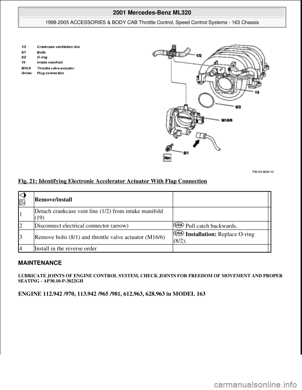
Fig. 21: Identifying Electronic Accelerator Actuator With Flap Connection
MAINTENANCE
LUBRICATE JOINTS OF ENGINE CONTROL SYSTEM, CHECK JOINTS FOR FREEDOM OF MOVEMENT AND PROPER
SEATING - AP30.10-P-3022GH
ENGINE 112.942 /970, 113.942 /965 /981, 612.963, 628.963 in MODEL 163
Remove/install
1Detach crankcase vent line (1/2) from intake manifold
(19)
2Disconnect electrical connector (arrow) Pull catch backwards.
3Remove bolts (8/1) and throttle valve actuator (M16/6) Installation: Replace O-ring
(8/2).
4Install in the reverse order
2001 Mercedes-Benz ML320
1998-2005 ACCESSORIES & BODY CAB Throttle Control, Speed Control Systems - 163 Chassis
me
Saturday, October 02, 2010 3:36:28 PMPage 36 © 2006 Mitchell Repair Information Company, LLC.
Page 3877 of 4133
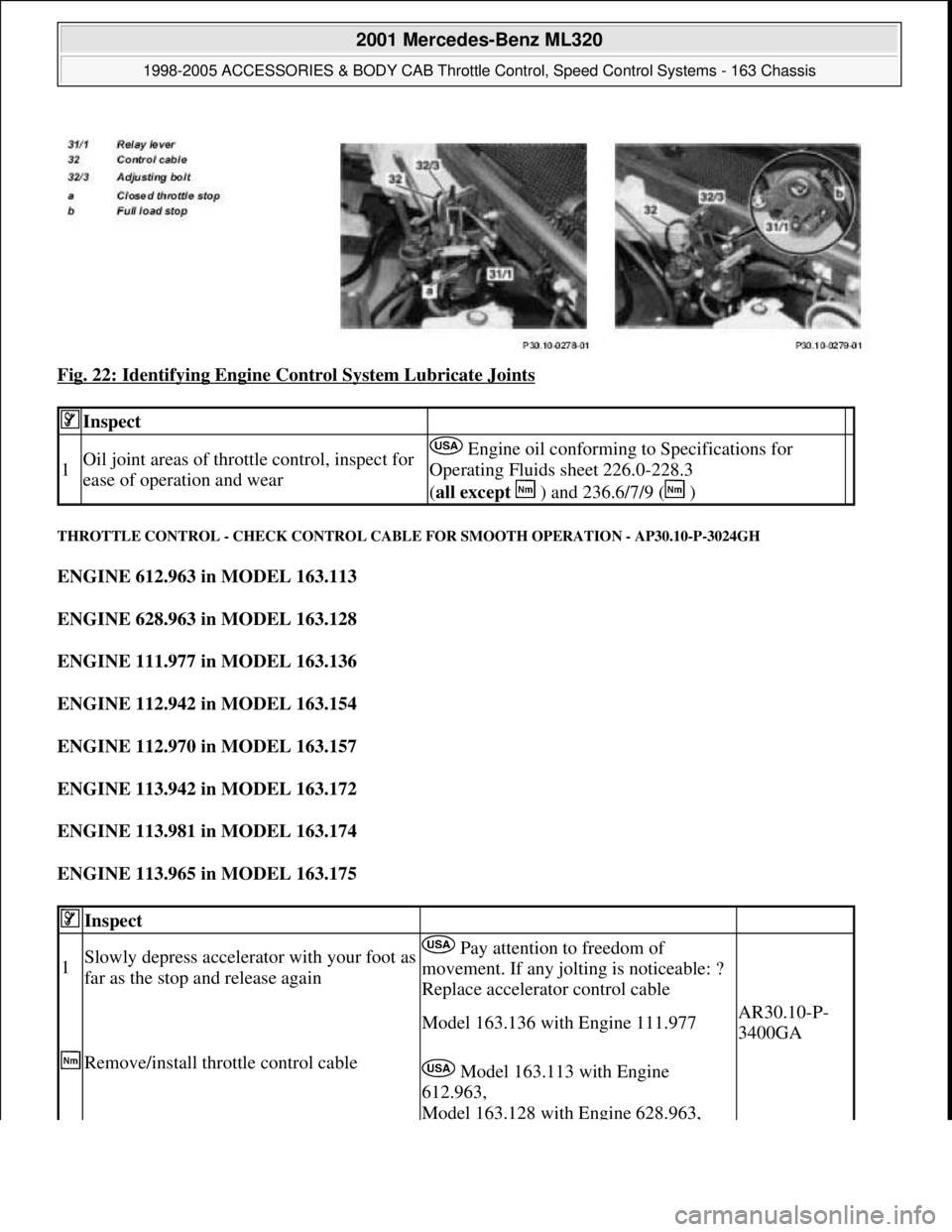
Fig. 22: Identifying Engine Control System Lubricate Joints
THROTTLE CONTROL - CHECK CONTROL CABLE FOR SMOOTH OPERATION - AP30.10-P-3024GH
ENGINE 612.963 in MODEL 163.113
ENGINE 628.963 in MODEL 163.128
ENGINE 111.977 in MODEL 163.136
ENGINE 112.942 in MODEL 163.154
ENGINE 112.970 in MODEL 163.157
ENGINE 113.942 in MODEL 163.172
ENGINE 113.981 in MODEL 163.174
ENGINE 113.965 in MODEL 163.175
Inspect
1Oil joint areas of throttle control, inspect for
ease of operation and wear Engine oil conforming to Specifications for
Operating Fluids sheet 226.0-228.3
(all except ) and 236.6/7/9 ( )
Inspect
1Slowly depress accelerator with your foot as
far as the stop and release again Pay attention to freedom of
movement. If any jolting is noticeable: ?
Replace accelerator control cable
Remove/install throttle control cable
Model 163.136 with Engine 111.977AR30.10-P-
3400GA
Model 163.113 with Engine
612.963,
Model 163.128 with Engine 628.963,
2001 Mercedes-Benz ML320
1998-2005 ACCESSORIES & BODY CAB Throttle Control, Speed Control Systems - 163 Chassis
me
Saturday, October 02, 2010 3:36:28 PMPage 37 © 2006 Mitchell Repair Information Company, LLC.
Page 3883 of 4133
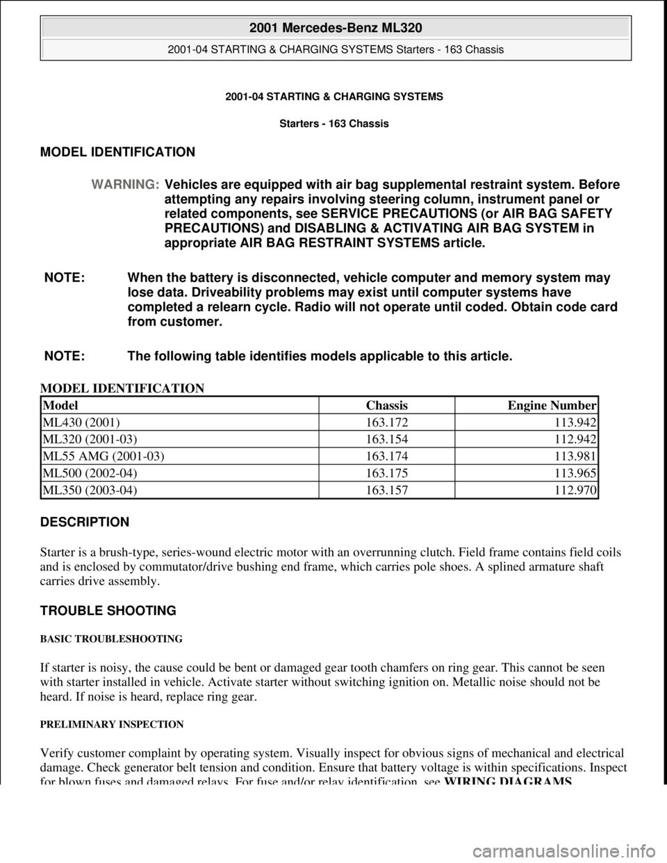
2001-04 STARTING & CHARGING SYSTEMS Starters - 163 Chassis
MODEL IDENTIFICATION
MODEL IDENTIFICATION
DESCRIPTION
Starter is a brush-type, series-wound el ectric motor with an overrunning clutch. Field frame contains field coils
and is enclosed by commutator/drive bushing end frame, which carries pole shoes. A splined armature shaft
carries drive assembly.
TROUBLE SHOOTING
BASIC TROUBLESHOOTING
If starter is noisy, the cause could be bent or damaged gear tooth chamfers on ring gear. This cannot be seen
with starter installed in ve hicle. Activate starter without switching ignition on. Me tallic noise should not be
heard. If noise is he ard, replace ring gear.
PRELIMINARY INSPECTION
Verify customer complaint by operating system. Visually inspect for obvious signs of mechanical and electrical
damage. Check generator belt tension and condition. Ensure that battery voltage is within specifications. Inspect
for blown fuses and damaged relays. For fuse and/or relay identification, see WIRING DIAGRAMS
.
WARNING:
Vehicles are equipped with air bag supplemental restraint system. Before
attempting any repairs involving steer ing column, instrument panel or
related components, see SERVICE PRECAUTIONS (or AIR BAG SAFETY
PRECAUTIONS) and DISABLING & ACTIVATING AIR BAG SYSTEM in
appropriate AIR BAG REST RAINT SYSTEMS article.
NOTE: When the battery is di sconnected, vehicle computer and memory system may
lose data. Driveability problems may exist until computer systems have
completed a relearn cycle. Radio will not operate until coded. Obtain code card
from customer.
NOTE: The following table identifies mo dels applicable to this article.
ModelChassisEngine Number
ML430 (2001)163.172113.942
ML320 (2001-03)163.154112.942
ML55 AMG (2001-03)163.174113.981
ML500 (2002-04)163.175113.965
ML350 (2003-04)163.157112.970
2001 Mercedes-Benz ML320
2001-04 STARTING & CHARGING SYSTEMS Starters - 163 Chassis
2001 Mercedes-Benz ML320
2001-04 STARTING & CHARGING SYSTEMS Starters - 163 Chassis
me
Saturday, October 02, 2010 3:19:47 PMPage 1 © 2006 Mitchell Repair Information Company, LLC.
me
Saturday, October 02, 2010 3:19:50 PMPage 1 © 2006 Mitchell Repair Information Company, LLC.
Page 3884 of 4133
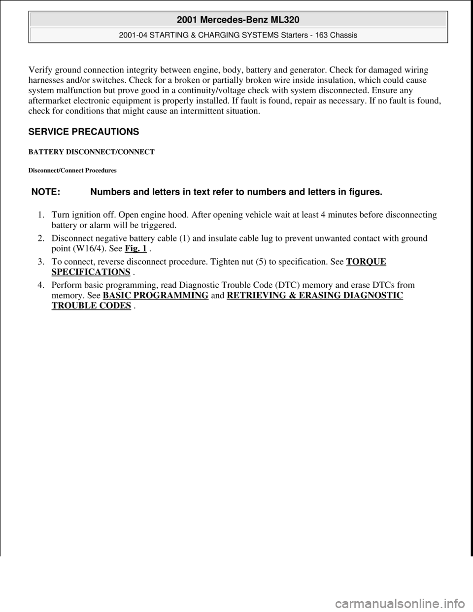
Verify ground connection integrity between engine, body, battery and generator. Check for damaged wiring
harnesses and/or switches. Check fo r a broken or partially broken wire inside insulation, which could cause
system malfunction but prove good in a continuity/vol tage check with system disconnected. Ensure any
aftermarket electronic e quipment is properly installed. If fault is found, repair as necessary. If no fault is found,
check for conditions that might cause an intermittent situation.
SERVICE PRECAUTIONS
BATTERY DISCONNECT/CONNECT
Disconnect/Connect Procedures
1. Turn ignition off. Open engine hood. After opening ve hicle wait at least 4 minutes before disconnecting
battery or alarm wi ll be triggered.
2. Disconnect negative battery cable (1) and insulate cable lug to prevent unwanted contact with ground
point (W16/4). See Fig. 1
.
3. To connect, reverse disconnect procedur e. Tighten nut (5) to specification. See TORQUE
SPECIFICATIONS .
4. Perform basic programming, read Diagnostic Tr ouble Code (DTC) memory and erase DTCs from
memory. See BASIC PROGRAMMING
and RETRIEVING & ERASING DIAGNOSTIC
TROUBLE CODES .
NOTE: Numbers and letters in text refe
r to numbers and letters in figures.
2001 Mercedes-Benz ML320
2001-04 STARTING & CHARGING SYSTEMS Starters - 163 Chassis
me
Saturday, October 02, 2010 3:19:47 PMPage 2 © 2006 Mitchell Repair Information Company, LLC.
Page 3891 of 4133
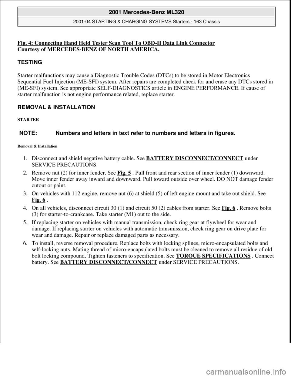
Fig. 4: Connecting Hand Held Tester Scan Tool To OBD-II Data Link Connector
Courtesy of MERCEDES-BENZ OF NORTH AMERICA.
TESTING
Starter malfunctions may cause a Di agnostic Trouble Codes (DTCs) to be stored in Motor Electronics
Sequential Fuel Injection (ME-SFI) sy stem. After repairs are completed check for and erase any DTCs stored in
(ME-SFI) system. See appropriate SE LF-DIAGNOSTICS article in ENGINE PERFORMANCE. If cause of
starter malfunction is not engine pe rformance related, replace starter.
REMOVAL & INSTALLATION
STARTER
Removal & Installation
1. Disconnect and shield negative battery cable. See BATTERY DISCONNECT/CONNECT under
SERVICE PRECAUTIONS.
2. Remove nut (2) for inner fender. See Fig. 5
. Pull front and rear section of inner fender (1) downward.
Move inner fender away inward and downward. Pull toward outside over wheel. DO NOT damage fender
cutout or paint.
3. On vehicles with 112 engine, remove nut (6) at shield (5) of left engine mount and take out shield. See
Fig. 6
.
4. On all vehicles, disconnect circuit 30 (1) and circuit 50 (2) cables from starter. See Fig. 6
. Remove bolts
(3) for starter-to-crankcase. Take starter (M1) out to the side.
5. If replacing starter on vehicles with manual transmission, check ring gear at flywheel for wear and
damage. If replacing starter on vehicles with auto matic transmission, check ring gear on drive plate for
wear and damage. Repair or repl ace damaged parts as necessary.
6. To install, reverse removal proce dure. Replace bolts with locking splines, micro-encapsulated bolts and
self-locking nuts. Mating thread of mi cro-encapsulated bolts must be cleaned to remove all residue of old
bolt locking compound. Tighten fasteners to specification. See TORQUE SPECIFICATIONS
. Connect
battery. See BATTERY DISCONNECT/CONNECTunder SERVICE PRECAUTIONS.
NOTE: Numbers and letters in text refe
r to numbers and letters in figures.
2001 Mercedes-Benz ML320
2001-04 STARTING & CHARGING SYSTEMS Starters - 163 Chassis
me
Saturday, October 02, 2010 3:19:47 PMPage 9 © 2006 Mitchell Repair Information Company, LLC.