1997 MERCEDES-BENZ ML350 check engine
[x] Cancel search: check enginePage 3464 of 4133
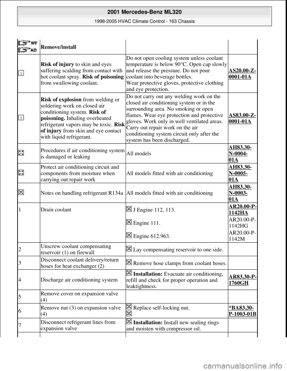
Remove/install
Risk of injury to skin and eyes
suffering scalding from contact with
hot coolant spray. Risk of poisoning
from swallowing coolant.
Do not open cooling system unless coolant
temperature is below 90°C. Open cap slowly
and release the pressure. Do not pour
coolant into beverage bottles.
Wear protective gloves, protective clothing
and eye protection.
AS20.00-Z-
0001-01A
Risk of explosion from welding or
soldering work on closed air
conditioning system. Risk of
poisoning. Inhaling overheated
refrigerant vapors may be toxic. Risk
of injury from skin and eye contact
with liquid refrigerant.Do not carry out any welding work on the
closed air conditioning system or in the
surrounding area. No smoking or open
flames. Wear eye protection and protective
gloves. Work only in well ventilated areas.
Carry out repair work on the air
conditioning system circuit only after the
system has been discharged.
AS83.00-Z-
0001-01A
Procedures if air conditioning system
is damaged or leakingAll models
AH83.30-
N-0004-
01A
Protect air conditioning circuit and
components from moisture when
carrying out repair work
All models fitted with air conditioning
AH83.30-
N-0005-
01A
Notes on handling refrigerant R134aAll models fitted with air conditioning
AH83.30-
N-0003-
01A
1Drain coolant J Engine 112, 113.AR20.00-P-
1142HA
Engine 111.AR20.00-P-
1142HG
Engine 612.963.AR20.00-P-
1142M
2Unscrew coolant compensating
reservoir (1) on firewall Lay compensating reservoir to one side.
3Disconnect coolant delivery/return
hoses for heat exchanger (2) Remove hose clamps from coolant hoses.
4Discharge air conditioning system
Installation: Evacuate air conditioning,
refill and check for proper operation and
leaktightness.AR83.30-P-
1760GH
5Remove cover on expansion valve
(4)
6Remove nut (3) on expansion valve
(4) Replace self-locking nut.
*BA83.30-
P-1003-01B
7Disconnect refrigerant lines from
expansion valve Installation: Install new sealing rings
and moisten with compressor oil.
2001 Mercedes-Benz ML320
1998-2005 HVAC Climate Control - 163 Chassis
me
Saturday, October 02, 2010 3:23:19 PMPage 220 © 2006 Mitchell Repair Information Company, LLC.
Page 3482 of 4133

GF54.30-P-3003A
Indicator/warning messages triggered via CAN data buses, function
24.10.96
MODEL
129, 140 as of 1.6.96,
163, 168, 170,
202 as of 1.8.96,
208 up to 31.7.99,
210 as of 1.6.96 up to 30.6.99
Indicator and warning displays triggered via CAN
Low brake fluid level/parking brake indicator lamp (A1e7)
The parking brake signal comes from the traction system
control module.
The brake fluid signal comes directly from the switch (S11)
(except model 163).
Brake pad wear indicator lamp (A1e6)
The parking brake signal comes from the traction system
control module (N47)
Low engine oil level indicator lamp (A1e12)
The oil level signal comes from the injection system control
module (N3).
For vehicles with ASSYST, also refer to document: ASSYST
engine oil monitoring.
Preglow indicator lamp (A1e16)
The signal comes directly from the injection system control
module (N3).
Coolant level and temperature warning lamp (A1e11) model 168
only as of 9.99
The coolant temperature signal comes from the injection
system control module (N3)
-----------------------------------------------------------------------------------------
ABS MIL (A1e17)
The parking brake signal comes from the traction system
control module (N47).
"CHECK ENGINE" MIL (A1e26),
I
only
The signal comes from the injection system control module (N3)
ETS (A1e35) or ASR (A1e22) or ESP (A1e42) MIL
Lamp illuminated if there is a fault in the respective system.
The signal comes from the traction system control module
(N47).
ETS (A1e36) or ASR (A1e21) or ESP (A1e41) warning lamp
The lamp indicates that the respective system is active.
The signal comes from the traction system control module
(N47).
-----------------------------------------------------------------------------------------
Severe leak warning (
I
as of 97 only)
The fuel reserve indicator lamp (A1e4) flashes. The signal
comes from the injection system control module (N3).
The warning takes place at the earliest 30 minutes after cold
start with the engine idling and the vehicle stationary.
Also refer to document: Purge system with leak test, function
Fog lamps indicator lamp (A1e57), model 163 only except
I
)
The signal comes from the All-activity module (AAM, N10)
"LOW RANGE" indicator lamp (A1e53), model 163 only
The signal comes from the transfer case control module (N78)
Active service system (ASSYST)
Engines 112, 113, 611 (engines with oil
sensor)
GF00.20-P-2009A
Engine oil monitoring, function
Model 210 as of 01.03.97 with engine M111,
OM602, OM604, OM605 and OM606
As of 06.97 models 129, 140, 170, 202 except
engines 112, 113, 611
(Valid for engines with low oil level switch).
GF00.20-P-2009B
Displaying coolant temperature, function
Model 168 as of 9.99
GF54.30-P-3020GC
Purge system with leak test, function
GF47.30-P-3016L
Bus systems, overall function
GF54.00-P-0004A
Copyright DaimlerChrysler AG 04.06.2006 CD-Ausgabe G/10/04 . This WIS print-out will not be recorde
d by Modification services.
Page 1
Page 3489 of 4133
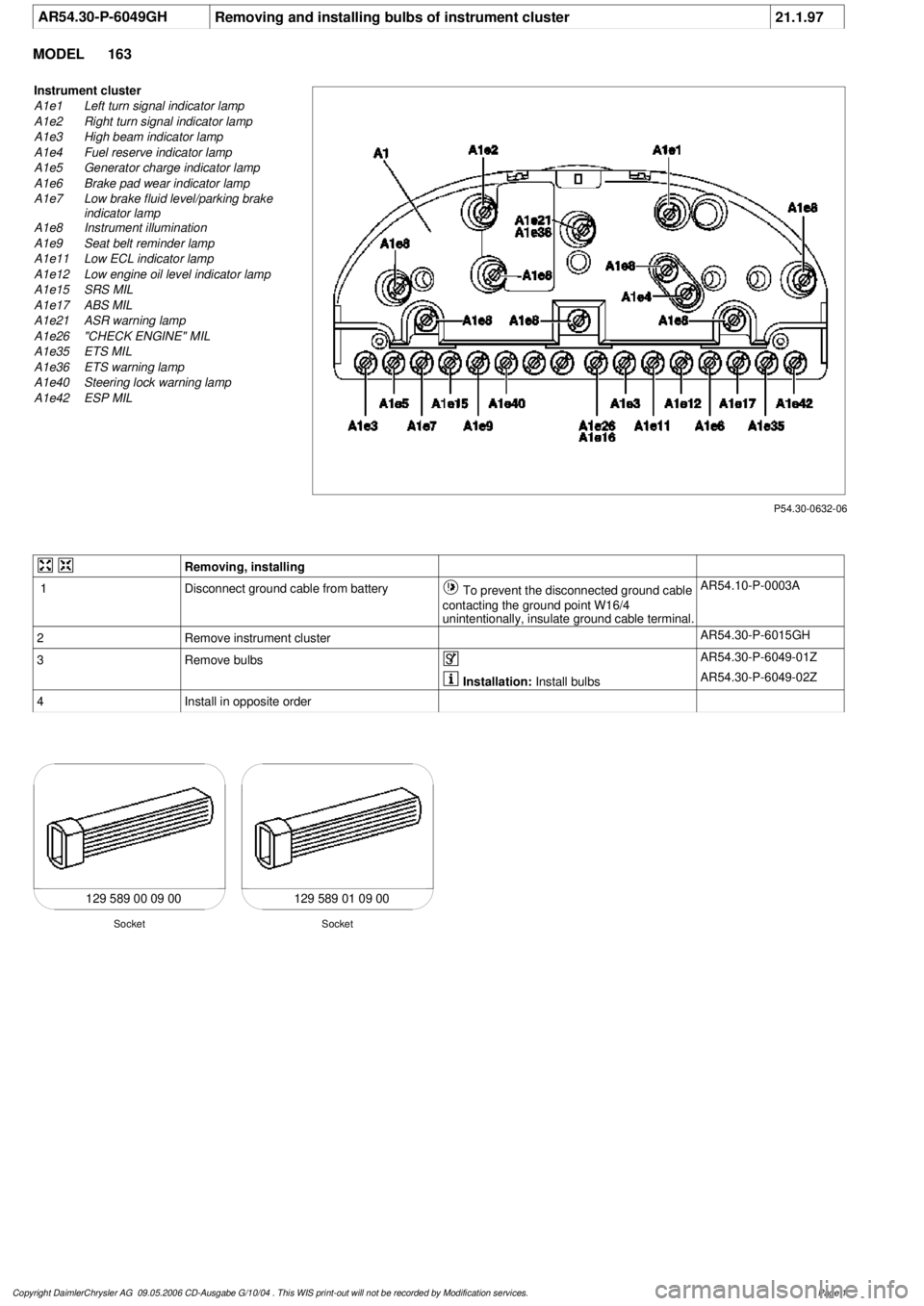
AR54.30-P-6049GH
Removing and installing bulbs of instrument cluster
21.1.97
MODEL
163
P54.30-0632-06
Instrument cluster
A1e1
Left turn signal indicator lamp
A1e2
Right turn signal indicator lamp
A1e3
High beam indicator lamp
A1e4
Fuel reserve indicator lamp
A1e5
Generator charge indicator lamp
A1e6
Brake pad wear indicator lamp
A1e7
Low brake fluid level/parking brake
indicator lamp
A1e8
Instrument illumination
A1e9
Seat belt reminder lamp
A1e11
Low ECL indicator lamp
A1e12
Low engine oil level indicator lamp
A1e15
SRS MIL
A1e17
ABS MIL
A1e21
ASR warning lamp
A1e26
"CHECK ENGINE" MIL
A1e35
ETS MIL
A1e36
ETS warning lamp
A1e40
Steering lock warning lamp
A1e42
ESP MIL
Removing, installing
1
Disconnect ground cable from battery
To prevent the disconnected ground cable
contacting the ground point W16/4
unintentionally, insulate ground cable terminal.
AR54.10-P-0003A
2
Remove instrument cluster
AR54.30-P-6015GH
3
Remove bulbs
AR54.30-P-6049-01Z
Installation:
Install bulbs
AR54.30-P-6049-02Z
4
Install in opposite order
129 589 00 09 00 129 589 01 09 00
Socket
Socket
Copyright DaimlerChrysler AG 09.05.2006 CD-Ausgabe G/10/04 . This WIS print-out will not be recorde
d by Modification services.
Page 1
Page 3498 of 4133

AF54.30-P-8400A
Instrument cluster indicates: Oil sensor defective, oil level below min. or oil level
above max. with engine running and at operating temperature. No DTC stored.
19.5.98
MODEL
129.0, 163.1, 202.0, 208.3 /4, 210.0 /2 /6, 220.0 /1 with ENGINE 112
MODEL
129.0, 163.1, 202.0, 208.3 /4, 210.0 /2, 220.0 /1 with ENGINE 113
Damage code
Cause
Remedy
54 201 90
Oil low, connector defective or coding error
1
Shut off engine and wait 2 min. (key
position 0)
Instrument cluster indicates oil sensor
defective, oil level below min. or oil level
above max. with engine warm and running.
No DTC stored in DTC memory!
2
Check oil level with oil dipstick
3
Check oil level on instrument cluster:
- Key in steering wheel lock position 2,
engine not running
- Wait until - - - - - - appears on
instrument cluster
- When this is displayed press the reset
button for the tripodometer twice within
1 sec. (display appears only after
expiration of a waiting time (max. 30
min.) depending on engine oil
temperature)
Oil level is at bottom mark on oil dipstick
and instrument cluster indicates:
-1L
, -
1,5L
or -2L
#
4
Add quantity of oil indicated on
instrument cluster display and repeat
test.
Oil level at upper mark on dipstick and
instrument cluster indicates either oil level
okay or -1L
, -
1,5L
, -2L
#
5
Recode instrument cluster
AF54.30-P-8600A
Problem still present
#
6
Check cable to oil sensor, oil sensor
connectors, control module and fuse
box (see wiring diagram) for good contact
Copyright DaimlerChrysler AG 05.06.2006 CD-Ausgabe G/10/04 . This WIS print-out will not be recorde
d by Modification services.
Page 1
Page 3740 of 4133
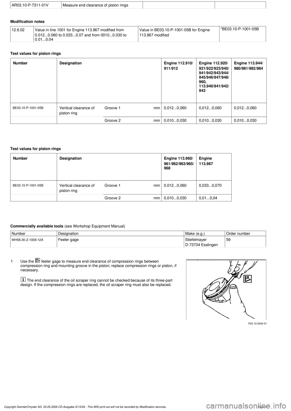
AR03.10-P-7311-01V
Measure end clearance of piston rings
Modification notes
12.6.02
Value in line 1001 for Engine 113.967 modified from
0.012...0.060 to 0.033...0.07 and from 0010...0.030 to
0.01...0.04
Value in BE03.10-P-1001-05B for Engine
113.967 modified
*BE03.10-P-1001-05B
Test values for piston rings
Number
Designation
Engine 112.910/
911/912
Engine 112.920/
921/922/923/940/
941/942/943/944/
945/946/947/948/
960,
113.940/941/942/
943
Engine 113.944/
980/981/982/984
BE03.10-P-1001-05B
Vertical clearance of
piston ring
Groove 1
mm
0,012...0,0600,012...0,0600,012...0,060
Groove 2
mm
0,010...0,0300,010...0,0300,010...0,030
Test values for piston rings
Number
Designation
Engine 113.960/
961/962/963/965/
968
Engine
113.967
BE03.10-P-1001-05B
Vertical clearance of
piston ring
Groove 1
mm
0,012...0,0600,033...0,070
Groove 2
mm
0,010...0,030
0,01...0,04
Commercially available tools
(see Workshop Equipment Manual)
Number
Designation
Make (e.g.)
Order number
WH58.30-Z-1008-12A
Feeler gage
Stiefelmayer
D-73734 Esslingen
59
P03.10-2034-01
1
Use the
feeler gage to measure end clearance of compression rings between
compression ring and mounting groove in the piston; replace compression rings or piston, if
necessary.
The end clearance of the oil scraper ring cannot be checked because of its three-part
design. If the compression rings are replaced, the oil scraper ring must also be replaced.
Copyright DaimlerChrysler AG 20.05.2006 CD-Ausgabe G/10/04 . This WIS print-out will not be recorde
d by Modification services.
Page 1
Page 3741 of 4133
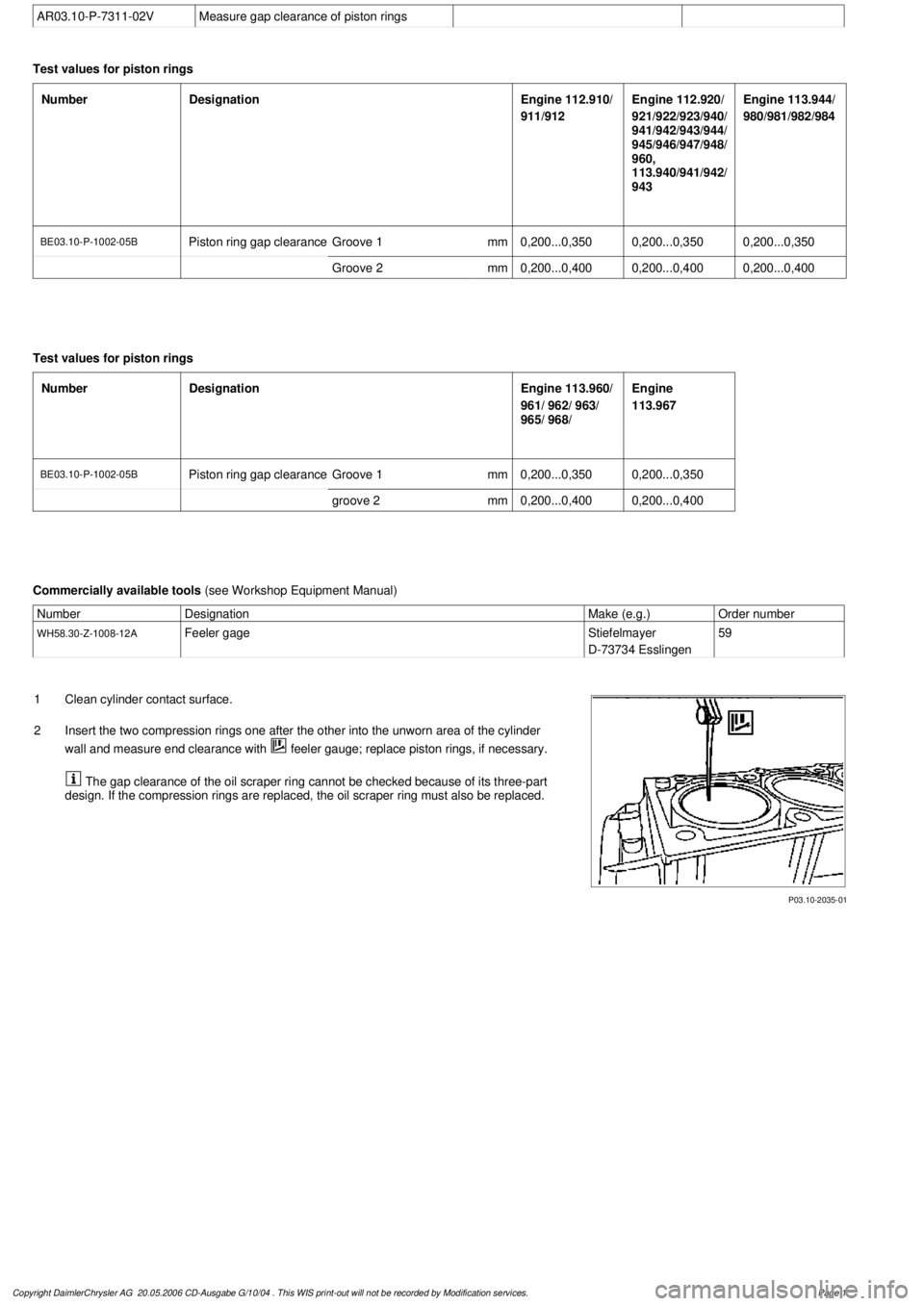
AR03.10-P-7311-02V
Measure gap clearance of piston rings
Test values for piston rings
Number
Designation
Engine 112.910/
911/912
Engine 112.920/
921/922/923/940/
941/942/943/944/
945/946/947/948/
960,
113.940/941/942/
943
Engine 113.944/
980/981/982/984
BE03.10-P-1002-05B
Piston ring gap clearance
Groove 1
mm
0,200...0,3500,200...0,3500,200...0,350
Groove 2
mm
0,200...0,4000,200...0,4000,200...0,400
Test values for piston rings
Number
Designation
Engine 113.960/
961/ 962/ 963/
965/ 968/
Engine
113.967
BE03.10-P-1002-05B
Piston ring gap clearance
Groove 1
mm
0,200...0,3500,200...0,350
groove 2
mm
0,200...0,4000,200...0,400
Commercially available tools
(see Workshop Equipment Manual)
Number
Designation
Make (e.g.)
Order number
WH58.30-Z-1008-12A
Feeler gage
Stiefelmayer
D-73734 Esslingen
59
P03.10-2035-01
1
Clean cylinder contact surface.
2
Insert the two compression rings one after the other into the unworn area of the cylinder
wall and measure end clearance with
feeler gauge; replace piston rings, if necessary.
The gap clearance of the oil scraper ring cannot be checked because of its three-part
design. If the compression rings are replaced, the oil scraper ring must also be replaced.
Copyright DaimlerChrysler AG 20.05.2006 CD-Ausgabe G/10/04 . This WIS print-out will not be recorde
d by Modification services.
Page 1
Page 3746 of 4133

11
Oil piston pin (2) and conrod bush
12
Assemble piston (3) and conrod (4)
Install piston (3) with arrow in direction of
travel.
13
Push in piston pin (2) by hand
14
Insert circlip (1) of piston pin (2) in the groove
on piston (3)
Do not damage piston (3). Place a clean
cloth underneath.
15
Oil cleaned parts (cylinder bore, conrod
bearing journal, conrod bearing shells and
pistons)
16
Fit on tensioning strap (10) and tension
Piston ring gaps must be offset 120°.
Tensioning strap
*000589041400
17
Install piston (3) with arrow pointing in
direction of travel
Rotate crankshaft far enough so that the
connecting rod when inserting piston into
cylinder bore does not line up at the
connecting rod journal!
18
Inspect conrod bolts (6)
AR03.10-P-6111-01BV
Thread and shank length
*BE03.10-P-1001-03A
19
Install conrod bearings and fit on conrod
bearing cap (5)
The connecting rod bearing shell (7) with
oil drilling (arrow) must be mounted in the
connecting rod, otherwise the piston pin (2) is
not lubricated.
The anti-twist locks (8) of the connecting rod
bearing shells (7) must be seated in the
grooves (9) in the conrods (4) and connecting
rod bearing caps (5).
AR03.10-P-6111-06AV
The connecting rod and connecting rod
bearing cap are cracked (broken) (arrow).
They must not be installed the wrong side
round!
20
Tighten conrod bolts (6)
AR03.10-P-6111-02BV
*BA03.10-P-1001-01E
21
Rotate crankshaft
To inspect ease of operation.
22
Install oil pump
-
Ensure oil return flow check valve is
correctly located.
-
Clean strainer of oil pump.
-
Fill oil pump with engine oil before
installing so that it pumps oil when first
started.
All except models 203, 209, 211.061/065/070,
220 without 4MATIC, 230.474 /475
AR18.10-P-6020B
Model 203 without 4MATIC, 209,
211.061/065/070
AR18.10-P-6020PV
Model 203 with 4MATIC, model 220 with
4MATIC
AR18.10-P-6020PW
Model 230.474/475
AR18.10-P-6020R
23
Fit on cylinder head
Models 463.206/ 209/ 232/ 233/ 240/ 241/
243/ 244/ 245/ 246/ 247/ 248/ 249/ 250/ 254
AR01.30-P-5800GV
Engine 112 in model 129 and engine 113 in
models 129, 202, 208, 210
AR01.30-P-5800B
Engine 112 in models 170, 202, 208, 210,
220 and engine 113 in models 220,
230.474 /475
AR01.30-P-5800BA
Model 163
AR01.30-P-5800MV
Models 203, 209 with engines 112, 113
Models 211.061/065/070
AR01.30-P-5800PV
24
Fit on top part of oil pan
Model 463
AR01.45-P-7500FG
Model 230.474/475
AR01.45-P-7500R
Model 220 without 4MATIC
AR01.45-P-7500I
Model 220 with 4MATIC
AR01.45-P-7500IW
Model 210 with 4MATIC
AR01.45-P-7500FA
Model 210 without 4MATIC
AR01.45-P-7500F
Models 202, 208
AR01.45-P-7500FC
Model 203 without 4MATIC, 209 with engines
112,113
AR01.45-P-7500PV
Model 203 with 4MATIC
AR01.45-P-7500PW
Model 211.061/065/070
AR01.45-P-7500TV
Model 170
AR01.45-P-7500SV
Model 163
AR01.45-P-7500FB
Model 129
AR01.45-P-7500FD
Copyright DaimlerChrysler AG 20.05.2006 CD-Ausgabe G/10/04 . This WIS print-out will not be recorde
d by Modification services.
Page 3
Page 3752 of 4133
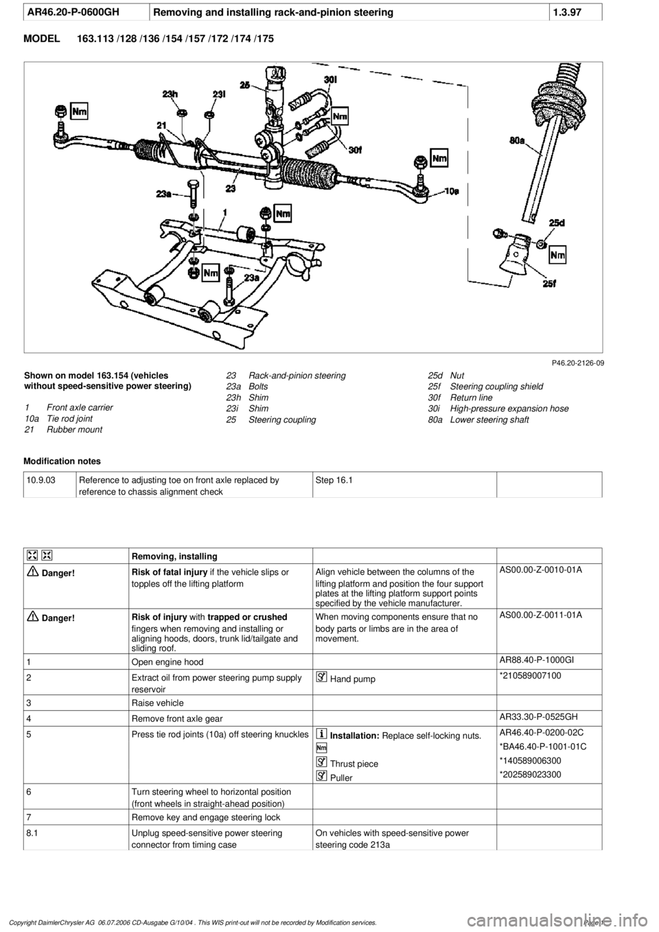
AR46.20-P-0600GH
Removing and installing rack-and-pinion steering
1.3.97
MODEL
163.113 /128 /136 /154 /157 /172 /174 /175
P46.20-2126-09
Shown on model 163.154 (vehicles
without speed-sensitive power steering)
1
Front axle carrier
10a
Tie rod joint
21
Rubber mount
25d
Nut
25f
Steering coupling shield
30f
Return line
30i
High-pressure expansion hose
80a
Lower steering shaft
23
Rack-and-pinion steering
23a
Bolts
23h
Shim
23i
Shim
25
Steering coupling
Modification notes
10.9.03
Reference to adjusting toe on front axle replaced by
reference to chassis alignment check
Step 16.1
Removing, installing
Danger!
Risk of fatal injury
if the vehicle slips or
topples off the lifting platform
Align vehicle between the columns of the
lifting platform and position the four support
plates
at the lifting platform support points
specified by the vehicle manufacturer.
AS00.00-Z-0010-01A
Danger!
Risk of injury
with
trapped or crushed
fingers when removing and installing or
aligning hoods, doors, trunk lid/tailgate and
sliding roof.
When moving components ensure that no
body parts or limbs are in the area of
movement.
AS00.00-Z-0011-01A
1
Open engine hood
AR88.40-P-1000GI
2
Extract oil from power steering pump supply
reservoir
Hand pump
*210589007100
3
Raise vehicle
4
Remove front axle gear
AR33.30-P-0525GH
5
Press tie rod joints (10a) off steering knuckles
Installation:
Replace self-locking nuts.
AR46.40-P-0200-02C
*BA46.40-P-1001-01C
Thrust piece
*140589006300
Puller
*202589023300
6
Turn steering wheel to horizontal position
(front wheels in straight-ahead position)
7
Remove key and engage steering lock
8.1
Unplug speed-sensitive power steering
connector from timing case
On vehicles with speed-sensitive power
steering code 213a
Copyright DaimlerChrysler AG 06.07.2006 CD-Ausgabe G/10/04 . This WIS print-out will not be recorde
d by Modification services.
Page 1