1997 MERCEDES-BENZ ML350 turn signal
[x] Cancel search: turn signalPage 3 of 4133

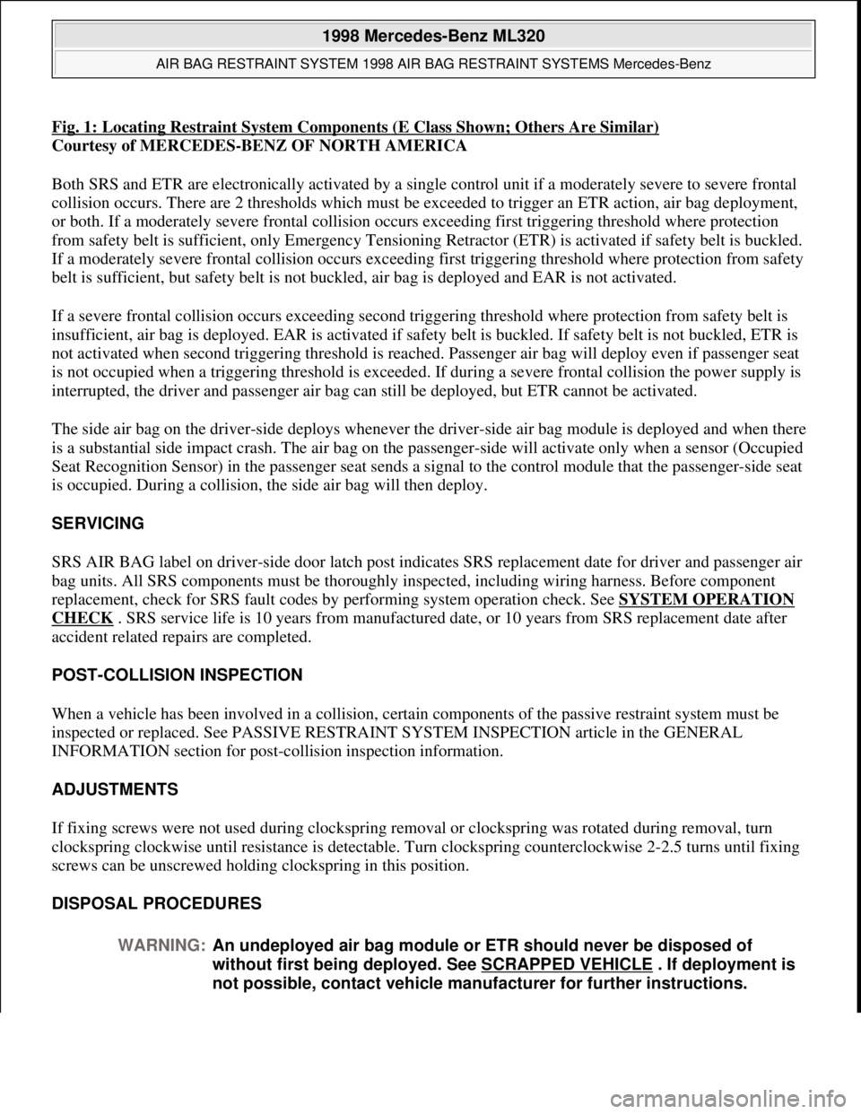
Fig. 1: Locating Restraint System Components (E Class Shown; Others Are Similar)
Courtesy of MERCEDES-BENZ OF NORTH AMERICA
Both SRS and ETR are electronically activated by a single control unit if a moderately severe to severe frontal
collision occurs. There are 2 thresholds which must be exceeded to trigger an ETR action, air bag deployment,
or both. If a moderately severe frontal collision occurs exceeding first triggering threshold where protection
from safety belt is sufficient, only Emergency Tensioning Retractor (ETR) is activated if safety belt is buckled.
If a moderately severe frontal collision occurs exceeding first triggering threshold where protection from safety
belt is sufficient, but safety belt is not buckled, air bag is deployed and EAR is not activated.
If a severe frontal collision occurs exceeding second triggering threshold where protection from safety belt is
insufficient, air bag is deployed. EAR is activated if safety belt is buckled. If safety belt is not buckled, ETR is
not activated when second triggering threshold is reached. Passenger air bag will deploy even if passenger seat
is not occupied when a triggering threshold is exceeded. If during a severe frontal collision the power supply is
interrupted, the driver and passenger air bag can still be deployed, but ETR cannot be activated.
The side air bag on the driver-side deploys whenever the driver-side air bag module is deployed and when there
is a substantial side impact crash. The air bag on the passenger-side will activate only when a sensor (Occupied
Seat Recognition Sensor) in the passenger seat sends a signal to the control module that the passenger-side seat
is occupied. During a collision, the side air bag will then deploy.
SERVICING
SRS AIR BAG label on driver-side door latch post indicates SRS replacement date for driver and passenger air
bag units. All SRS components must be thoroughly inspected, including wiring harness. Before component
replacement, check for SRS fault codes by performing system operation check. See SYSTEM OPERATION
CHECK . SRS service life is 10 years from manufactured date, or 10 years from SRS replacement date after
accident related repairs are completed.
POST-COLLISION INSPECTION
When a vehicle has been involved in a collision, certain components of the passive restraint system must be
inspected or replaced. See PASSIVE RESTRAINT SYSTEM INSPECTION article in the GENERAL
INFORMATION section for post-collision inspection information.
ADJUSTMENTS
If fixing screws were not used during clockspring removal or clockspring was rotated during removal, turn
clockspring clockwise until resistance is detectable. Turn clockspring counterclockwise 2-2.5 turns until fixing
screws can be unscrewed holding clockspring in this position.
DISPOSAL PROCEDURES
WARNING:An undeployed air bag module or ETR should never be disposed of
without first being deployed. See SCRAPPED VEHICLE
. If deployment is
not possible, contact vehicle manufacturer for further instructions.
1998 Mercedes-Benz ML320
AIR BAG RESTRAINT SYSTEM 1998 AIR BAG RESTRAINT SYSTEMS Mercedes-Benz
me
Saturday, October 02, 2010 3:33:13 PMPage 3 © 2006 Mitchell Repair Information Company, LLC.
Page 19 of 4133

CLEARING FAULT CODES
Connect Hand-Held Tester (965 589 00 01) to Data Link Connector (DLC). DLC is located in right rear corner
of engine compartment. It may be necessary to use Adapter (965 589 00 40 or 965 589 00 50) to connect HHT
to DLC. After HHT displays module number and version, press return key to start sequence. Using HHT,
follow HHT prompts to clear SRS fault codes. SRS codes are clear when ignition is turned on and SRS warning
light functions normally. See SYSTEM OPERATION CHECK
.
UNDERSTANDING DIAGNOSTIC CHART INFORMATION
SRS & ETR Diagnosis Chart Column Identification
For example, see Fig. 7
under DIAGNOSTIC TESTS. First column of chart identifies TEST STEP (1.0 for
example). Second column of chart identifies HHT fault code (017, 003 for example). First code in column is for
vehicles without side air bags. Second code in column (when listed) is for vehicles with side air bags only.
Other 5 columns are self-explanatory.
Using SRS & ETR Diagnosis Chart
For reading and understanding fault code diagnosis chart, use the following example: Read test step 3.0
(first column), HHT fault Code 002, 004 (second column). See Fig. 7
. Read TEST SCOPE/HHT
ACTUAL VALUE NO./TEXT column (third column). Driver-side air bag squib connector R12/3 is
being tested. HHT will identify if problem is with too much resistance or not enough resistance in driver-
side air bag squib circuit. Read TEST CONDITION column (fifth column). Test circuit with HHT
connected to DLC, with ignition in position "2". Read NOMINAL VALUE/HHT DISPLAY column
(sixth column). HHT will display a check or an "F". If HHT displays a check, circuit is okay. If HHT
displays an "F", go to step 3.1.
Read TEST CONNECTION (NOT FOR HHT) column (forth column). Driver-Side air bag squib
connector R12/3, terminals No. 1 and 2 are identified. Read TEST CONDITION column. Test circuit
027
(Passenger Seat Occupation Signal)22
032, 033
(Communication Interference)(1)
034
(Digital Crash Output, Harness Fault)(1)
035
(Analog Crash Output, Harness Fault)(1)
036
(Auto Child Seat Recognition Light)22.0, 23.0
(1)Test information is not available.
NOTE: To properly identify components or connectors being tested, see COMPONENT
IDENTIFICATION table.
1998 Mercedes-Benz ML320
AIR BAG RESTRAINT SYSTEM 1998 AIR BAG RESTRAINT SYSTEMS Mercedes-Benz
me
Saturday, October 02, 2010 3:33:14 PMPage 19 © 2006 Mitchell Repair Information Company, LLC.
Page 55 of 4133

5 Contents
Vehicle careCleaning and care
of the vehicle .............................278
Power washer ..............................279
Tar stains .....................................279
Paintwork, painted body
components .................................279
Engine cleaning ..........................280
Vehicle washing .........................280
Ornamental moldings ................280
Headlamps, taillamps,
turn signal lenses ......................280
Window cleaning ........................ 281
Wiper blades ............................... 281
Light alloy wheels ...................... 281
Instrument cluster ..................... 281
Steering wheel and
gear selector lever ...................... 281Cup holder .................................. 282
Seat belts ..................................... 282
Headliner .................................... 282
Upholstery .................................. 282
Hard plastic trim items ............. 282
Plastic and rubber parts ........... 282
Technical dataSpare parts service ....................... 284
Warranty coverage ........................ 284
Identification labels ...................... 285
Layout of poly-V-belt drive ........... 286
Technical data ................................ 287
Fuels, coolants, lubricants
etc. – capacities ........................ 292
Engine oils ...................................... 294
Engine oil additives ...................... 294
Air conditioner refrigerant .......... 294Brake fluid ......................................294
Premium unleaded gasoline ........295
Fuel requirements .........................295
Gasoline additives .........................296
Coolants ...........................................296
Consumer information ..................298
IndexIndex ................................................300
Page 77 of 4133

27 Central locking system
Te ch n ica l
data Instruments
and controlsOperationDrivingInstrument
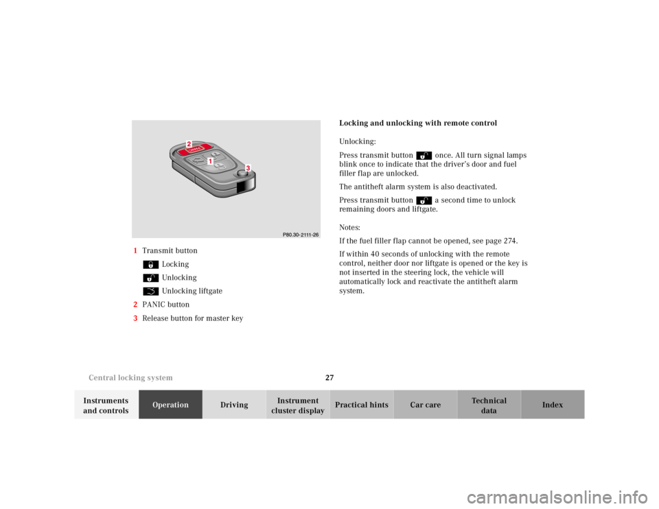
cluster displayPractical hints Car care Index 1Transmit button
‹ Locking
ΠUnlocking
Š Unlocking liftgate
2PANIC button
3Release button for master keyLocking and unlocking with remote control
Unlocking :
Press transmit button Πonce. All turn signal lamps
blink once to indicate that the driver’s door and fuel
filler flap are unlocked.
The antitheft alarm system is also deactivated.
Press transmit button Πa second time to unlock
remaining doors and liftgate.
Notes:
If the fuel filler flap cannot be opened, see page 274.
If within 40 seconds of unlocking with the remote
control, neither door nor liftgate is opened or the key is
not inserted in the steering lock, the vehicle will
automatically lock and reactivate the antitheft alarm
system.
Page 78 of 4133

28 Central locking system
Te ch n ica l
data Instruments
and controlsOperationDrivingInstrument
cluster displayPractical hints Car care Index
Locking:
Press transmit button ‹ once. All turn signal lamps
blink three times to indicate that the vehicle is locked
and the antitheft alarm is activated.
Notes:
If the turn signal lamps do not blink three times when
locking the vehicle, a door, the liftgate, or the hood is
not properly closed. Close the respective element and
lock the vehicle again with the remote control.
If the vehicle cannot be locked or unlocked by pressing
the transmit button, then it may be necessary to change
the batteries in the remote control or to synchronize the
remote control, see page 270 and page 271.
Unlocking the liftgate
Press transmit button Š to unlock the liftgate. This
also deactivates the antitheft alarm.
Important!
A minimum height clearance of 7 ft. (2.15 m) is
required to open the liftgate.Panic button
To activate press and hold button (1) for at least one
second. An audible alarm and blinking turn signal
lamps will operate for approximately 3 minutes.
Additionally the interior lights switch on automatically
for approximately 3 minutes.
To deactivate press button (1) again, or press transmit
button‹, ŒorŠ on the remote control, or
turn key in steering lock to position 1.
Page 85 of 4133

35 Antitheft alarm system
Te ch n ica l
data Instruments
and controlsOperationDrivingInstrument
cluster displayPractical hints Car care Index Antitheft alarm system
The indicator lamp is located in the center console.
The antitheft alarm is automatically armed or disarmed
with the remote control by locking or unlocking the
vehicle.
The antitheft alarm is armed within approximately
15 seconds after locking the vehicle with the remote
control.
A blinking lamp in the center console indicates that the
alarm is armed.
Notes:
Use of the key in the front door locks does not arm or
disarm the antitheft alarm system.
The alarm sounds when unlocking the driver’s door
with the mechanical key. Cancel alarm by turning key in
steering lock to position 1, or with the remote control by
pressing buttonŒ.
If the vehicle battery voltage falls below 10 volts, the
alarm is automatically canceled and the antitheft alarm
system is disarmed. When the voltage is above this
value again, the antitheft alarm system is armed again.Operation:
Once the alarm system has been armed, the turn signal
lamps will flash rapidly (approximately 3 minutes) and
the horn will sound intermittently (approximately
30 seconds) when someone:
•opens a door,
•opens the liftgate,
•opens the hood,
•breaks a window,
•attempts to raise the vehicle.
The alarm will stay on even if the activating element (a
door, for example) is immediately closed.
If the alarm stays on for more than 20 seconds, an
emergency call is initiated automatically. See Tele Aid
on page 148.
Note:
The alarm system will cycle three times when triggered.
The interior lights are automatically switched on when
the alarm comes on and go out when canceling the
alarm.
Page 86 of 4133

36 Tow-away protection
Te ch n ica l
data Instruments
and controlsOperationDrivingInstrument
cluster displayPractical hints Car care Index
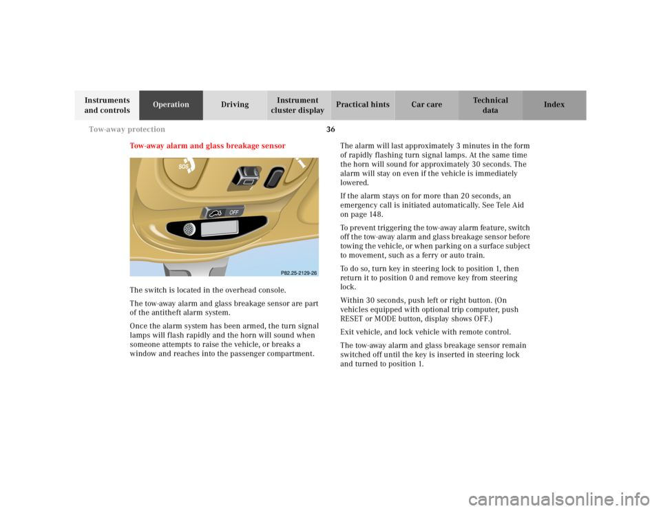
Tow-away alarm and glass breakage sensor
The switch is located in the overhead console.
The tow-away alarm and glass breakage sensor are part
of the antitheft alarm system.
Once the alarm system has been armed, the turn signal
lamps will flash rapidly and the horn will sound when
someone attempts to raise the vehicle, or breaks a
window and reaches into the passenger compartment.The alarm will last approximately 3 minutes in the form
of rapidly flashing turn signal lamps. At the same time
the horn will sound for approximately 30 seconds. The
alarm will stay on even if the vehicle is immediately
lowered.
If the alarm stays on for more than 20 seconds, an
emergency call is initiated automatically. See Tele Aid
on page 148.
To prevent triggering the tow-away alarm feature, switch
off the tow-away alarm and glass breakage sensor before
towing the vehicle, or when parking on a surface subject
to movement, such as a ferry or auto train.
To do so, turn key in steering lock to position 1, then
return it to position 0 and remove key from steering
lock.
Within 30 seconds, push left or right button. (On
vehicles equipped with optional trip computer, push
RESET or MODE button, display shows OFF.)
Exit vehicle, and lock vehicle with remote control.
The tow-away alarm and glass breakage sensor remain
switched off until the key is inserted in steering lock
and turned to position 1.
Page 127 of 4133

77 Instrument cluster
Te ch n ica l
data Instruments
and controlsOperationDrivingInstrument
cluster displayPractical hints Car care Index 1Coolant temperature gauge, see page 81
2Outside temperature indicator (optional), see
page 82
3Fuel gauge with reserve and fuel cap placement
warning lamp, see page 220
4Left turn signal indicator lamp, see exterior lamp
switch, page 90
5Knob for odometer / trip odometer readout / reset,
FSS indicator, and intensity of instrument lamps,
see page 80
64-ETS+ and ESP warning lamp, see page 221
For 4-ETS+ (four wheel electronic traction system),
see page 203;
for ESP (electronic stability program), see page 205.7Speedometer
8Selectable:
Trip odometer, see page 80
Main odometer, see page 80
FSS display, see page 87
Engine oil level indicator, see page 89
9Right turn signal indicator lamp, see exterior lamp
switch, page 90
10Knob for setting clock, see page 80
11Tachometer, see page 82
12Gear range indicator display, see selector lever
positions, page 168
13Clock, see page 80