Page 2171 of 4133
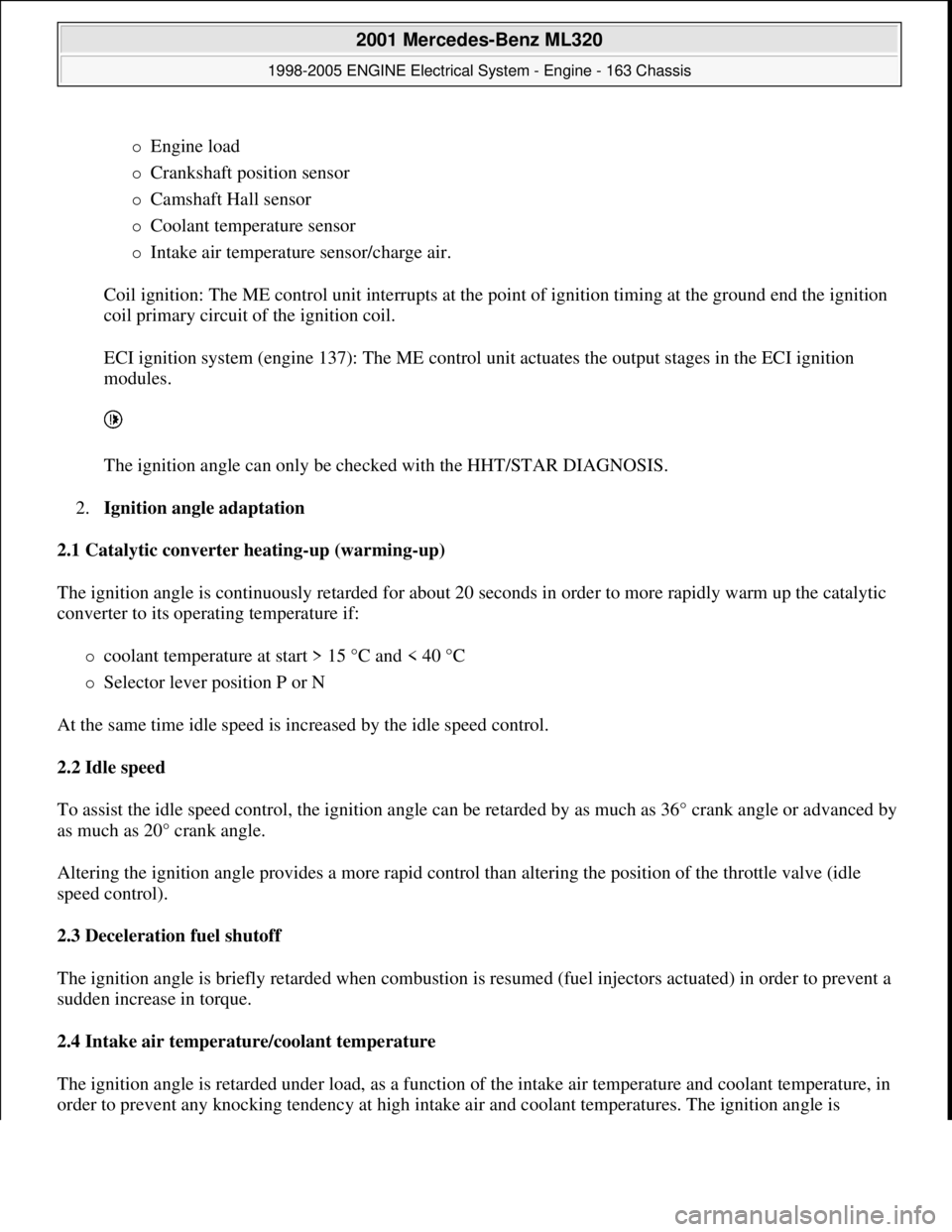
Engine load
Crankshaft position sensor
Camshaft Hall sensor
Coolant temperature sensor
Intake air temperature sensor/charge air.
Coil ignition: The ME control unit interrupts at the point of ignition timing at the ground end the ignition
coil primary circuit of the ignition coil.
ECI ignition system (engine 137): The ME control unit actuates the output stages in the ECI ignition
modules.
The ignition angle can only be checked with the HHT/STAR DIAGNOSIS.
2.Ignition angle adaptation
2.1 Catalytic converter heating-up (warming-up)
The ignition angle is continuously retarded for about 20 seconds in order to more rapidly warm up the catalytic
converter to its operating temperature if:
coolant temperature at start > 15 °C and < 40 °C
Selector lever position P or N
At the same time idle speed is increased by the idle speed control.
2.2 Idle speed
To assist the idle speed control, the ignition angle can be retarded by as much as 36° crank angle or advanced by
as much as 20° crank angle.
Altering the ignition angle provides a more rapid control than altering the position of the throttle valve (idle
speed control).
2.3 Deceleration fuel shutoff
The ignition angle is briefly retarded when combustion is resumed (fuel injectors actuated) in order to prevent a
sudden increase in torque.
2.4 Intake air temperature/coolant temperature
The ignition angle is retarded under load, as a function of the intake air temperature and coolant temperature, in
order to prevent an
y knocking tendency at high intake air and coolant temperatures. The ignition angle is
2001 Mercedes-Benz ML320
1998-2005 ENGINE Electrical System - Engine - 163 Chassis
me
Saturday, October 02, 2010 3:18:54 PMPage 17 © 2006 Mitchell Repair Information Company, LLC.
Page 2204 of 4133
ENGINE 112.970 in MODEL 163.157
ENGINE 113.942 in MODEL 163.172
ENGINE 113.981 in MODEL 163.174
ENGINE 113.965 in MODEL 163.175
Fig. 28: Identifying Starter Remove/Install Components
Modification notes
3.9.03Check ring gear, newly
recordedStage 7
Removing/installing
Risk of explosion caused by
oxyhydrogen gas. Risk of
poisoning and caustic burns
caused by swallowing battery
acid. Risk of injury through
burns to skin and eyes from
battery acid or when handling
damaged lead-acid batteriesNo fire, sparks, open
flames or smoking. Wear
acid-resistant gloves,
clothing and safety
glasses. Only pour battery
acid into suitable and
appropriately marked
containers.AS54.10-Z-0001-01A
Notes on self-locking nuts and
bolts AH00.00-N-0001-01A
2001 Mercedes-Benz ML320
1998-2005 ENGINE Electrical System - Engine - 163 Chassis
me
Saturday, October 02, 2010 3:18:54 PMPage 50 © 2006 Mitchell Repair Information Company, LLC.
Page 2205 of 4133
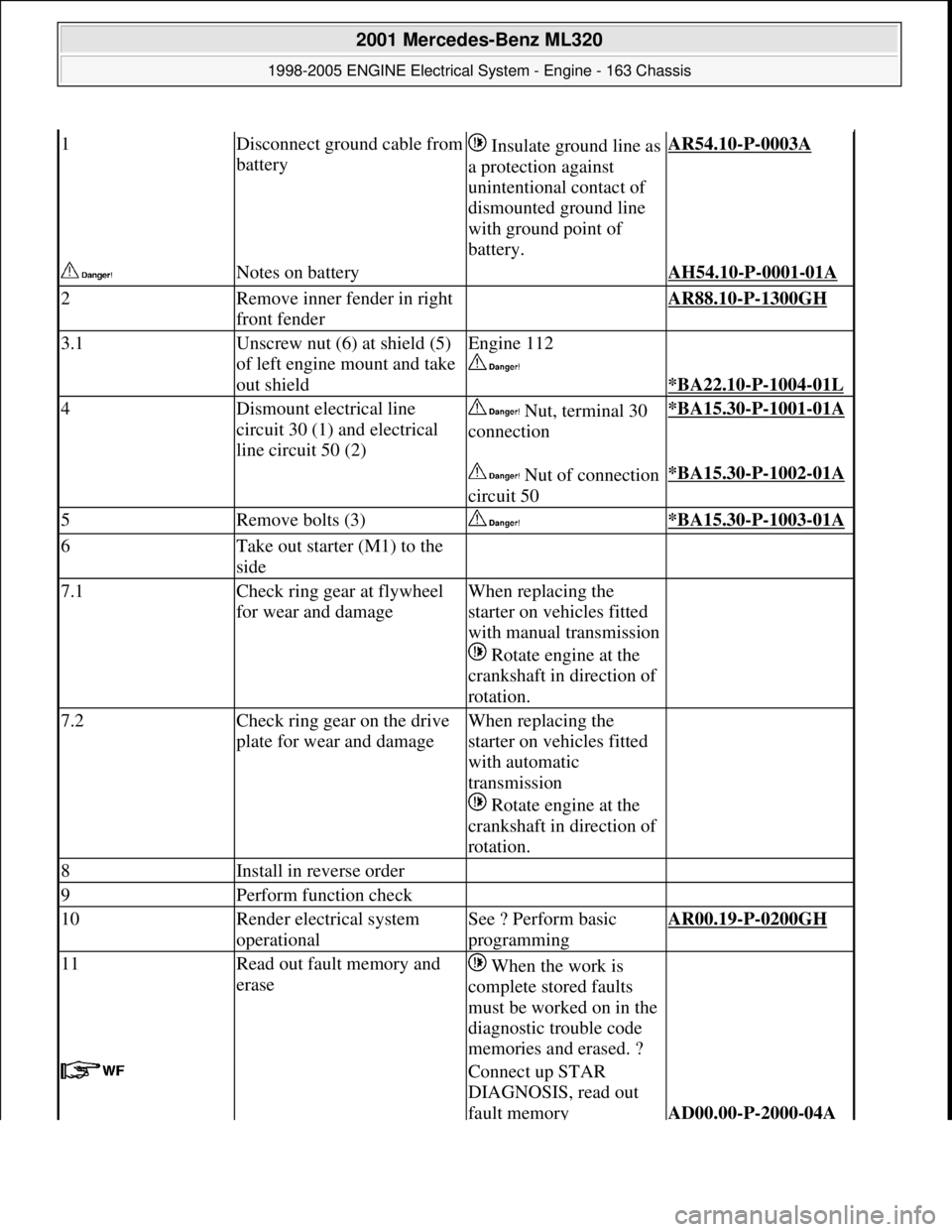
1Disconnect ground cable from
battery Insulate ground line as
a protection against
unintentional contact of
dismounted ground line
with ground point of
battery.AR54.10-P-0003A
Notes on battery AH54.10-P-0001-01A
2Remove inner fender in right
front fender AR88.10-P-1300GH
3.1Unscrew nut (6) at shield (5)
of left engine mount and take
out shieldEngine 112
*BA22.10-P-1004-01L
4Dismount electrical line
circuit 30 (1) and electrical
line circuit 50 (2) Nut, terminal 30
connection*BA15.30-P-1001-01A
Nut of connection
circuit 50*BA15.30-P-1002-01A
5Remove bolts (3) *BA15.30-P-1003-01A
6Take out starter (M1) to the
side
7.1Check ring gear at flywheel
for wear and damageWhen replacing the
starter on vehicles fitted
with manual transmission
Rotate engine at the
crankshaft in direction of
rotation.
7.2Check ring gear on the drive
plate for wear and damageWhen replacing the
starter on vehicles fitted
with automatic
transmission
Rotate engine at the
crankshaft in direction of
rotation.
8Install in reverse order
9Perform function check
10Render electrical system
operationalSee ? Perform basic
programmingAR00.19-P-0200GH
11Read out fault memory and
erase When the work is
complete stored faults
must be worked on in the
diagnostic trouble code
memories and erased. ?
Connect up STAR
DIAGNOSIS, read out
fault memory
AD00.00-P-2000-04A
2001 Mercedes-Benz ML320
1998-2005 ENGINE Electrical System - Engine - 163 Chassis
me
Saturday, October 02, 2010 3:18:54 PMPage 51 © 2006 Mitchell Repair Information Company, LLC.
Page 2207 of 4133
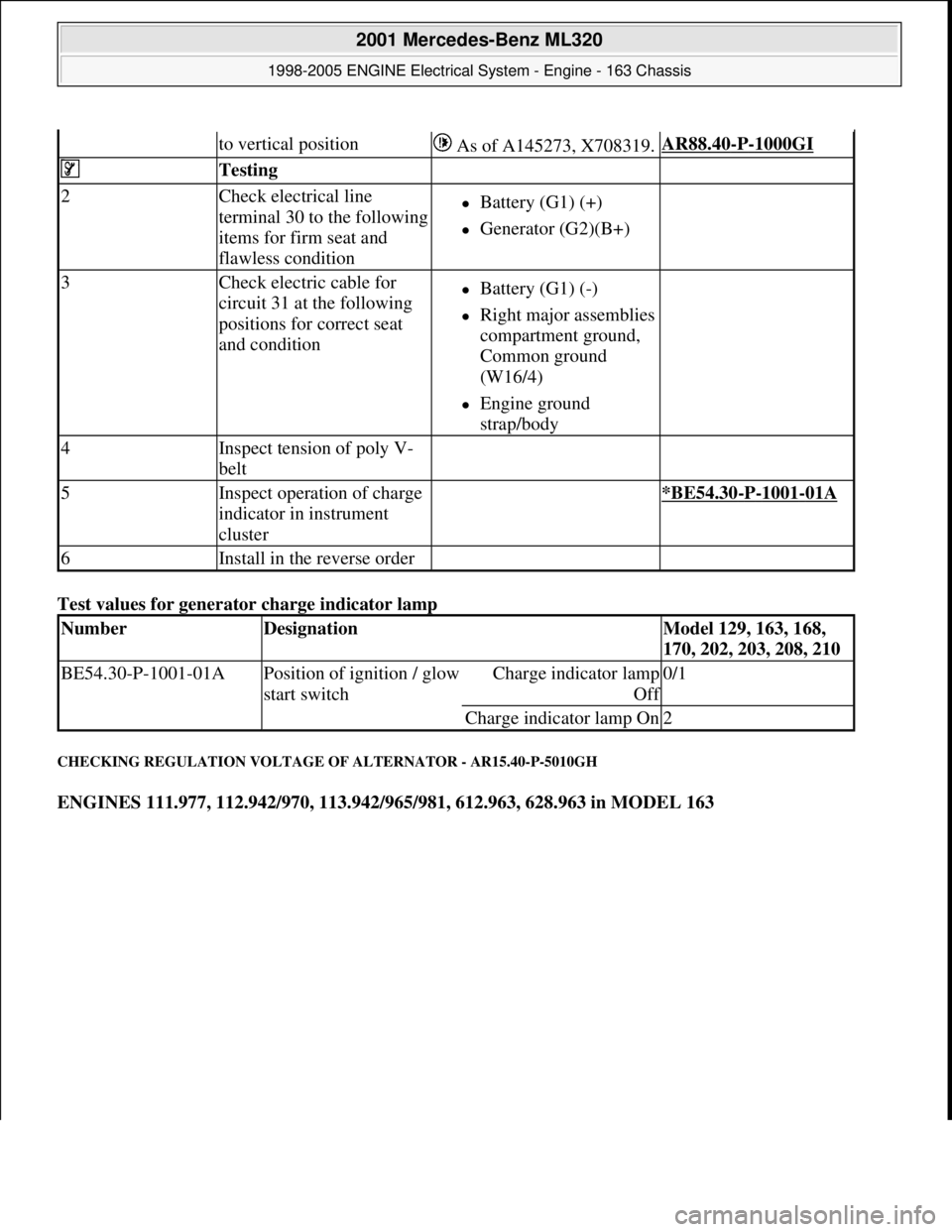
Test values for generator charge indicator lamp
CHECKING REGULATION VOLTAGE OF ALTERNATOR - AR15.40-P-5010GH
ENGINES 111.977, 112.942/970, 113.942/965/981, 612.963, 628.963 in MODEL 163
to vertical position As of A145273, X708319.AR88.40-P-1000GI
Testing
2Check electrical line
terminal 30 to the following
items for firm seat and
flawless conditionBattery (G1) (+)
Generator (G2)(B+)
3Check electric cable for
circuit 31 at the following
positions for correct seat
and conditionBattery (G1) (-)
Right major assemblies
compartment ground,
Common ground
(W16/4)
Engine ground
strap/body
4Inspect tension of poly V-
belt
5Inspect operation of charge
indicator in instrument
cluster *BE54.30-P-1001-01A
6Install in the reverse order
NumberDesignationModel 129, 163, 168,
170, 202, 203, 208, 210
BE54.30-P-1001-01APosition of ignition / glow
start switchCharge indicator lamp
Of
f
0/1
Charge indicator lamp On2
2001 Mercedes-Benz ML320
1998-2005 ENGINE Electrical System - Engine - 163 Chassis
me
Saturday, October 02, 2010 3:18:54 PMPage 53 © 2006 Mitchell Repair Information Company, LLC.
Page 2208 of 4133

Fig. 30: Identifying Connection Diagram - Checking For Alternator Regulation Voltage
Checking
Risk of explosion caused
by oxyhydrogen gas. Risk
of poisoning and caustic
burns caused by
swallowing battery acid.
Risk of injury caused by
burns to skin and eyes
from battery acid or when
handling damaged lead-
acid batteriesNo fire, sparks, open flames
or smoking. Wear acid-
resistant gloves, clothing and
safety glasses. Only pour
battery acid into suitable and
appropriately marked
containers.
AS54.10-Z-0001-01A
Notes on battery AH54.10-P-0001-01A
1Check condition of
battery (G1) AR54.10-P-1129Z
2Check whether
preconditions for
alternator testing have
been fulfilled AR15.40-P-5009GH
3Attach volt ampere tester
(079) according to
connection plan Volt ampere tester with
load resistance*WH58.30-Z-1002-09A
Volt ampere tester ETT
011.00*WH58.30-Z-1003-09A
Risk of accident caused Secure vehicle to prevent it AS00.00-Z-0005-01A
2001 Mercedes-Benz ML320
1998-2005 ENGINE Electrical System - Engine - 163 Chassis
me
Saturday, October 02, 2010 3:18:54 PMPage 54 © 2006 Mitchell Repair Information Company, LLC.
Page 2209 of 4133

by vehicle starting off by
itself when engine is
running. Risk of injury
caused by contusions and
burns during starting
procedure or when
working near the running
enginefrom moving by itself.
Wear closed and snug-fitting
work clothes.
Do not grasp hot or rotating
parts.
4Start engine
5Check function of charge
indicator lamp when
engine is idling and with
increasing engine speed
(up to 3000 rpm) Charge indicator lamp
must extinguish.
6Load battery (G1) using a
permanent consumer and
check regulation voltage
of alternator (G2)Engines 111, 112, 113*BE15.40-P-1001-02A
Engines 612, 628*BE15.40-P-1001-02C
Volt ampere tester with
load resistance*WH58.30-Z-1002-09A
Volt ampere tester ETT
011.00*WH58.30-Z-1003-09A
Regulation voltage > 15.0
V: ?
Replace regulator
Engine 628
Engines 111, 112, 113
Replace alternator
(G2)
AR15.40-P-5760GH
Engine 612
Regulation voltage < 13.0
V: ?
Check electrical
connections for
charging system for
transition resistances;
repair if necessary.
Electrical connections OK: ?
AR15.40-P-5032GI
Check alternator (G2)
diodes AR15.40-P-9301-02EA
2001 Mercedes-Benz ML320
1998-2005 ENGINE Electrical System - Engine - 163 Chassis
me
Saturday, October 02, 2010 3:18:54 PMPage 55 © 2006 Mitchell Repair Information Company, LLC.
Page 2210 of 4133
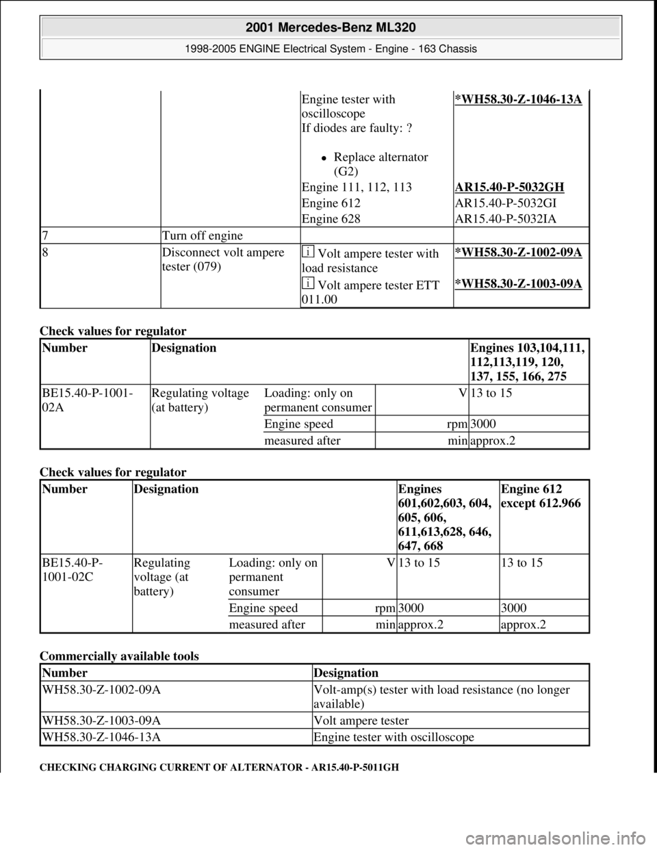
Check values for regulator
Check values for regulator
Commercially available tools
CHECKING CHARGING CURRENT OF ALTERNATOR - AR15.40-P-5011GH
Engine tester with
oscilloscope
If diodes are faulty: ?
Replace alternator
(G2)
*WH58.30-Z-1046-13A
Engine 111, 112, 113AR15.40-P-5032GH
Engine 612AR15.40-P-5032GI
Engine 628AR15.40-P-5032IA
7Turn off engine
8Disconnect volt ampere
tester (079) Volt ampere tester with
load resistance*WH58.30-Z-1002-09A
Volt ampere tester ETT
011.00*WH58.30-Z-1003-09A
NumberDesignationEngines 103,104,111,
112,113,119, 120,
137, 155, 166, 275
BE15.40-P-1001-
02ARegulating voltage
(at battery)Loading: only on
permanent consumerV13 to 15
Engine speedrpm3000
measured afterminapprox.2
NumberDesignationEngines
601,602,603, 604,
605, 606,
611,613,628, 646,
647, 668Engine 612
except 612.966
BE15.40-P-
1001-02CRegulating
voltage (at
battery)Loading: only on
permanent
consumerV13 to 1513 to 15
Engine speedrpm30003000
measured afterminapprox.2approx.2
NumberDesignation
WH58.30-Z-1002-09AVolt-amp(s) tester with load resistance (no longer
available)
WH58.30-Z-1003-09AVolt ampere tester
WH58.30-Z-1046-13AEngine tester with oscilloscope
2001 Mercedes-Benz ML320
1998-2005 ENGINE Electrical System - Engine - 163 Chassis
me
Saturday, October 02, 2010 3:18:54 PMPage 56 © 2006 Mitchell Repair Information Company, LLC.
Page 2211 of 4133
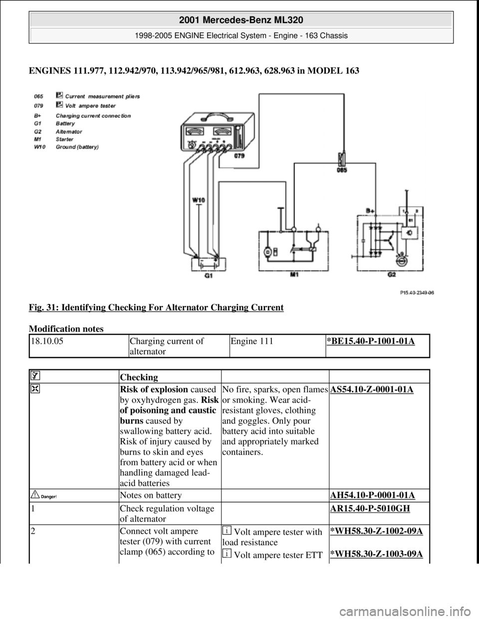
ENGINES 111.977, 112.942/970, 113.942/965/981, 612.963, 628.963 in MODEL 163
Fig. 31: Identifying Checking For Alternator Charging Current
Modification notes
18.10.05Charging current of
alternatorEngine 111*BE15.40-P-1001-01A
Checking
Risk of explosion caused
by oxyhydrogen gas. Risk
of poisoning and caustic
burns caused by
swallowing battery acid.
Risk of injury caused by
burns to skin and eyes
from battery acid or when
handling damaged lead-
acid batteriesNo fire, sparks, open flames
or smoking. Wear acid-
resistant gloves, clothing
and goggles. Only pour
battery acid into suitable
and appropriately marked
containers.AS54.10-Z-0001-01A
Notes on battery AH54.10-P-0001-01A
1Check regulation voltage
of alternator AR15.40-P-5010GH
2Connect volt ampere
tester (079) with current
clamp (065) according to Volt ampere tester with
load resistance*WH58.30-Z-1002-09A
Volt ampere tester ETT *WH58.30-Z-1003-09A
2001 Mercedes-Benz ML320
1998-2005 ENGINE Electrical System - Engine - 163 Chassis
me
Saturday, October 02, 2010 3:18:54 PMPage 57 © 2006 Mitchell Repair Information Company, LLC.