Page 2327 of 4133
Model 215.373/375
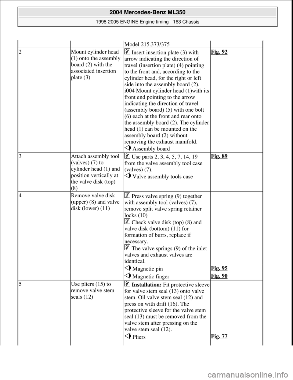
2Mount cylinder head
(1) onto the assembly
board (2) with the
associated insertion
plate (3) Insert insertion plate (3) with
arrow indicating the direction of
travel (insertion pl ate) (4) pointing
to the front and, according to the
cylinder head, for the right or left
side into the assembly board (2).
i004 Mount cylinder head (1)with its
front end pointing to the arrow
indicating the dir ection of travel
(assembly board) (5) with one bolt
(6) each at the front and rear onto
the assembly board (2). The cylinder
head (1) can be mounted on the
assembly board (2) without
removing the exhaust manifold.
Assembly boardFig. 92
3Attach assembly tool
(valves) (7) to
cylinder head (1) and
position vertically at
the valve disk (top)
(8) Use parts 2, 3, 4, 5, 7, 14, 19
from the valve assembly tool case
(valves) (7).
Valve assembly tools caseFig. 89
4Remove valve disk
(upper) (8) and valve
disk (lower) (11) Press valve spring (9) together
with assembly tool (valves) (7),
remove split valve spring retainer
locks (10)
Check valve disk (top) (8) and
valve disk (bottom) (11) for
formation of burrs, replace if
necessary.
The valve springs (9) of the inlet
valves and exhaust valves are
identical.
Magnetic pinFig. 95
Magnetic fingerFig. 90
5Use pliers (15) to
remove valve stem
seals (12) Installation: Fit protective sleeve
for valve stem seal (13) onto valve
stem. Oil valve stem seal (12) and
press on with drift (16). The
protective sleeve for the valve stem
seal (13) must be removed from the
valve stem after pressing on the
valve stem seal (12).
PliersFig. 77
2004 Mercedes-Benz ML350
1998-2005 ENGINE Engine timing - 163 Chassis
me
Saturday, October 02, 2010 3:39:38 PMPage 86 © 2006 Mitchell Repair Information Company, LLC.
Page 2328 of 4133
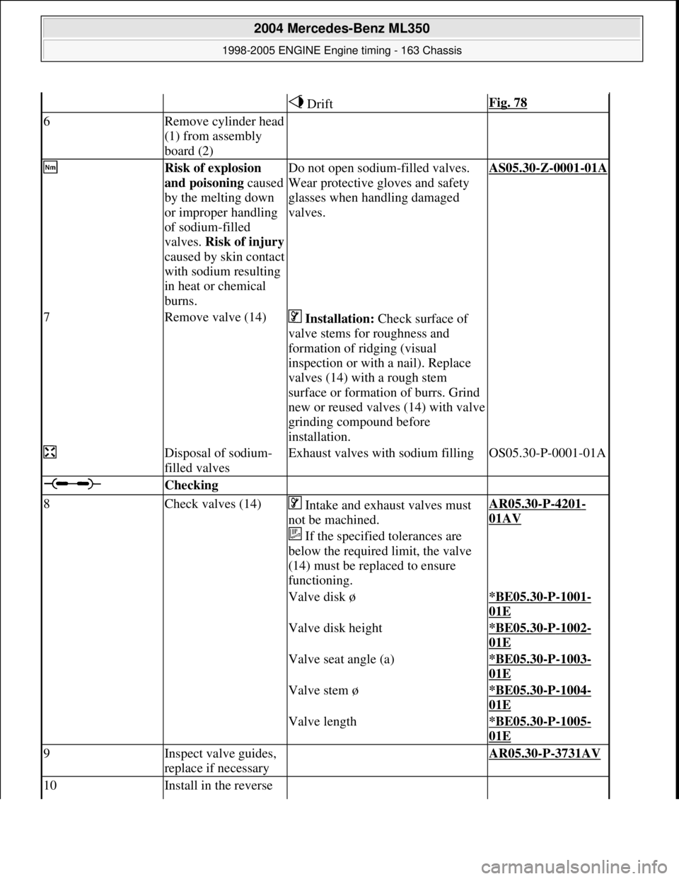
DriftFig. 78
6Remove cylinder head
(1) from assembly
board (2)
Risk of explosion
and poisoning caused
by the melting down
or improper handling
of sodium-filled
valves. Risk of injury
caused by skin contact
with sodium resulting
in heat or chemical
burns.Do not open sodium-filled valves.
Wear protective gloves and safety
glasses when handling damaged
valves.AS05.30-Z-0001-01A
7Remove valve (14) Installation: Check surface of
valve stems for roughness and
formation of ridging (visual
inspection or with a nail). Replace
valves (14) with a rough stem
surface or formation of burrs. Grind
new or reused valves (14) with valve
grinding compound before
installation.
Disposal of sodium-
filled valvesExhaust valves with sodium fillingOS05.30-P-0001-01A
Checking
8Check valves (14) Intake and exhaust valves must
not be machined.
If the specified tolerances are
below the required limit, the valve
(14) must be replaced to ensure
functioning.AR05.30-P-4201-
01AV
Valve disk ø*BE05.30-P-1001-
01E
Valve disk height*BE05.30-P-1002-
01E
Valve seat angle (a)*BE05.30-P-1003-
01E
Valve stem ø*BE05.30-P-1004-
01E
Valve length*BE05.30-P-1005-
01E
9Inspect valve guides,
replace if necessary AR05.30-P-3731AV
10Install in the reverse
2004 Mercedes-Benz ML350
1998-2005 ENGINE Engine timing - 163 Chassis
me
Saturday, October 02, 2010 3:39:38 PMPage 87 © 2006 Mitchell Repair Information Company, LLC.
Page 2329 of 4133
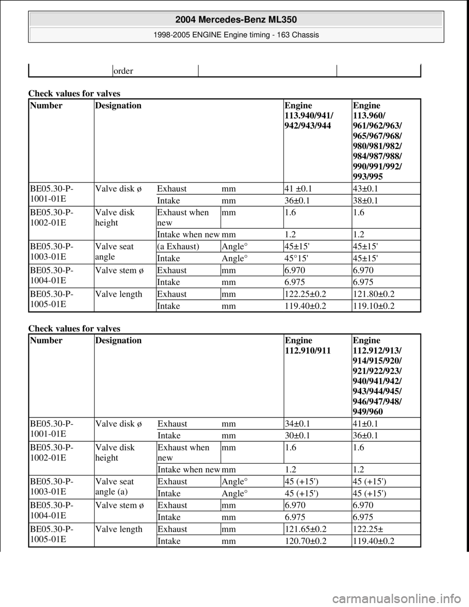
Check values for valves
Check values for valves
order
NumberDesignationEngine
113.940/941/
942/943/944Engine
113.960/
961/962/963/
965/967/968/
980/981/982/
984/987/988/
990/991/992/
993/995
BE05.30-P-
1001-01EValve disk øExhaustmm41 ±0.143±0.1
Intakemm36±0.138±0.1
BE05.30-P-
1002-01EValve disk
heightExhaust when
newmm1.61.6
Intake when newmm1.21.2
BE05.30-P-
1003-01EValve seat
angle(a Exhaust)Angle°45±15'45±15'
IntakeAngle°45°15'45±15'
BE05.30-P-
1004-01EValve stem øExhaustmm6.9706.970
Intakemm6.9756.975
BE05.30-P-
1005-01EValve lengthExhaustmm122.25±0.2121.80±0.2
Intakemm119.40±0.2119.10±0.2
NumberDesignationEngine
112.910/911Engine
112.912/913/
914/915/920/
921/922/923/
940/941/942/
943/944/945/
946/947/948/
949/960
BE05.30-P-
1001-01EValve disk øExhaustmm34±0.141±0.1
Intakemm30±0.136±0.1
BE05.30-P-
1002-01EValve disk
heightExhaust when
newmm1.61.6
Intake when newmm1.21.2
BE05.30-P-
1003-01EValve seat
angle (a)ExhaustAngle°45 (+15')45 (+15')
IntakeAngle°45 (+15')45 (+15')
BE05.30-P-
1004-01EValve stem øExhaustmm6.9706.970
Intakemm6.9756.975
BE05.30-P-
1005-01EValve lengthExhaustmm121.65±0.2122.25±
Intakemm120.70±0.2119.40±0.2
2004 Mercedes-Benz ML350
1998-2005 ENGINE Engine timing - 163 Chassis
me
Saturday, October 02, 2010 3:39:38 PMPage 88 © 2006 Mitchell Repair Information Company, LLC.
Page 2335 of 4133
2. Coat the outside of valve guide (5) with oil.
3. Position the valve guide (5) and knock into the cylinder head as far as the stop (arrow) of the insertion
drift (3). Check the secure seati ng of the valve guide (5). The instal lation depth of the valve guide (5)
is set by the drift punch (3).
Fig. 106: Identifying Valve Guide
4. Check the valve guide (5) with the feeler gauge (4). The side of the feeler gauge (4) marked
with '0' must be inserted completely into the valve gui de (5). The valve guide (5) must be replaced if the
feeler gauge (4) cannot be insert ed completely. The valve guide (5) is made of powdered metal, so
reaming is not possible.
Fig. 107: Identifying Valve Guide And Feeler Gauge
2004 Mercedes-Benz ML350
1998-2005 ENGINE Engine timing - 163 Chassis
me
Saturday, October 02, 2010 3:39:38 PMPage 94 © 2006 Mitchell Repair Information Company, LLC.
Page 2340 of 4133
Fig. 114: Identifying Feeler (102 589 01 23 00)
1. Clean bore of valve guide (1) (never use a hard object).
2. Inspect surface of bore for scores or signs of rubbi ng. If damage to the surface is present, the valve
guide must be replaced and the valve stem inspected for uneven areas. If the stem is damaged, the valve
must be replaced together with the valve guide.
Fig. 115: Identifying Valve Guide
3. If it is possible to inse rt the side of the hole gauge (3) marked with "+220" over its full length (5 mm)
into the valve guide, it is then necessary to repl ace the valve guide. Inspect bore of valve guide in
longitudinal and tran sverse direction.
Fig. 116: Inserting Side Of Hole Gauge
CHECK, REMOVE, INSTALL VA LVE GUIDES - AR05.30-P-3731AV
2004 Mercedes-Benz ML350
1998-2005 ENGINE Engine timing - 163 Chassis
me
Saturday, October 02, 2010 3:39:38 PMPage 99 © 2006 Mitchell Repair Information Company, LLC.
Page 2351 of 4133
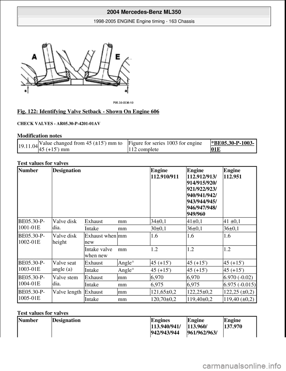
Fig. 122: Identifying Valve Setback - Shown On Engine 606
CHECK VALVES - AR05.30-P-4201-01AV
Modification notes
Test values for valves
Test values for valves
19.11.04Value changed from 45 (±15') mm to
45 (+15') mmFigure for series 1003 for engine
112 complete*BE05.30-P-1003-
01E
NumberDesignationEngine
112.910/911Engine
112.912/913/
914/915/920/
921/922/923/
940/941/942/
943/944/945/
946/947/948/
949/960Engine
112.951
BE05.30-P-
1001-01EValve disk
dia.Exhaustmm34±0,141±0,141 ±0,1
Intakemm30±0,136±0,136±0,1
BE05.30-P-
1002-01EValve disk
heightExhaust when
newmm1.61.61.6
Intake valve
when newmm1.21.21.2
BE05.30-P-
1003-01EValve seat
angle (a)ExhaustAngle°45 (+15')45 (+15')45 (+15')
IntakeAngle°45 (+15')45 (+15')45 (+15')
BE05.30-P-
1004-01EValve stem
dia.Exhaustmm6,9706,9706.970 (-0.02)
Intakemm6,9756,9756.975 (-0.015)
BE05.30-P-
1005-01EValve lengthExhaustmm121,65±0,2122,25±0,2122,25 (±0,2)
Intakemm120,70±0,2119,40±0,2119,40 (±0,2)
NumberDesignationEngines
113.940/941/
942/943/944Engine
113.960/
961/962/963/ Engine
137.970
2004 Mercedes-Benz ML350
1998-2005 ENGINE Engine timing - 163 Chassis
me
Saturday, October 02, 2010 3:39:39 PMPage 110 © 2006 Mitchell Repair Information Company, LLC.
Page 2352 of 4133
Fig. 123: Identifying Valve Dimensions
CHECKING AND MACHINING DIMENSIONS FOR VALVE SEATS - AR05.30-P-4510-01AV
Test values for valve seat rings
965/967/968/
980/981/982/
984/987/988/
990/991/992/
993/995
BE05.30-P-
1001-01EValve disk
dia.Exhaustmm41±0,143±0,136±0,1
Intakemm36±0,138±0,133±0,1
BE05.30-P-
1002-01EValve disk
heightExhaust when
newmm1.61.61.6
Intake valve
when newmm1.21.21.1
BE05.30-P-
1003-01EValve seat
angle(aExhaust)Angle°45±15'45±15'45±15'
IntakeAngle°45±15'45±15'45±15'
BE05.30-P-
1004-01EValve stem
dia.Exhaustmm6,9706,9706,970
Intakemm6,9756,9755,975
BE05.30-P-
1005-01EValve lengthExhaustmm122,25±0,2121,80±0,2104,30 ±0,2
Intakemm119,40±0,2119,10±0,2103,60 ±0,2
NumberDesignationEngine
112.910/
911Engine 112.912/
914/915/920/
921/922/923/
940/941/942/
943/944/945/
2004 Mercedes-Benz ML350
1998-2005 ENGINE Engine timing - 163 Chassis
me
Saturday, October 02, 2010 3:39:39 PMPage 111 © 2006 Mitchell Repair Information Company, LLC.
Page 2355 of 4133
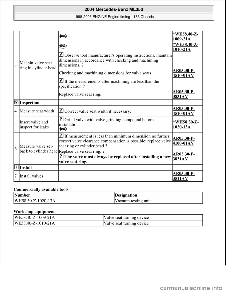
Commercially available tools
Workshop equipment
3Machin valve seat
ring in cylinder head
*WE58.40-Z-
1009-21A
*WE58.40-Z-
1010-21A
Observe tool manufacturer's operating instructions, maintain
dimensions in accordance with checking and machining
dimensions. ?
Checking and machining dime nsions for valve seatsAR05.30-P-
4510-01AV
If the measurements after machining are less than the
specification ?
Replace valve seat ring.AR05.30-P-
3831AV
Inspection
4Measure seat width Correct valve seat width if necessary.AR05.30-P-
4510-01AV
5Insert valve and
inspect for leaks Grind valve with valve grinding compound before
installation.
*WH58.30-Z-
1020-13A
6Measure valve set-
back to cylinder head
If measurement is less than minimum dimension no further
correct valve clearance compensation is possible; replace valve
seat ring or cylinder head ?AR05.30-P-
4100-01AV
Replace valve seat ring. ?
The valve must always be rep laced after installing a new
valve seat ring. AR05.30-P-
3831AV
Install
7Install valves AR05.30-P-
3511AV
NumberDesignation
WH58.30-Z-1020-13AVacuum testing unit
WE58.40-Z-1009-21AValve seat turning device
WE58.40-Z-1010-21AValve seat turning device
2004 Mercedes-Benz ML350
1998-2005 ENGINE Engine timing - 163 Chassis
me
Saturday, October 02, 2010 3:39:39 PMPage 114 © 2006 Mitchell Repair Information Company, LLC.