Page 2296 of 4133
i040*WH58.30-Z-
1003-28A
3Place camshaft bearing
bridge on board (4) Fig. 56
4
Remove the rocker arm
spindle (3) by tapping
gently with a hammer If it is tapped very hard, th ere is a danger of distorting the
camshaft bearing bridge and da maging the hollow rocker arm
spindle (3).
Fig. 53
Check
5
Inspect bearing
surfaces of rocker arms
for damage Pay attention to any long score marks caused by the
removal of the rocker arm spindl es (3). Replace the rocker arm
if damaged.
Installing
6
Insert the guide shafts
into the camshaft
bearing bridge. At the same time, preassemble the rocker arm on guide
shaft.
Fig. 54
Fig. 55
Risk of injury to skin
and eyes caused by
handling hot or glowing
objects.
Wear safety gloves, protective cl othing and safety glasses, if
necessary.AS00.00-Z-
0002-01A
7
Heat camshaft bearing
bridge to approx. 150°
C
Heat the camshaft bearing bridge uniformly, but do not
heat it over 160°C; there is a danger of structural changes.
WH58.30-Z-
1001-28A
*WH58.30-Z-
1003-28A
8Cool the rocker arm
spindle (3)
9
Place heated camshaft
bearing bridge on board
(4) Fig. 56
10Install rocker arm
spindle (3)
Insert the rocker arm spindle (3) in the camshaft bearing
bridge by tapping gently with a hammer and simultaneously
remove the guide shaft. Ensure that the rocker arms do not get
jammed.
11Align the rocker arm
spindle (3)
In order to align and secure the rocker arm spindle (3), fit
two screws through the mount ing bores in the camshaft
bearing bridge. The oil supply bores of the rocker arm spindle
(3) point towards the cylinder head.
Engines 112, 113 except engines 113.967 /990 in models 219,
engines 113.964 /971 /989 /993AR05.20-P-
7103AU
Engine 113.993 in model 463AR05.20-P-
7103GX
2004 Mercedes-Benz ML350
1998-2005 ENGINE Engine timing - 163 Chassis
me
Saturday, October 02, 2010 3:39:38 PMPage 55 © 2006 Mitchell Repair Information Company, LLC.
Page 2299 of 4133
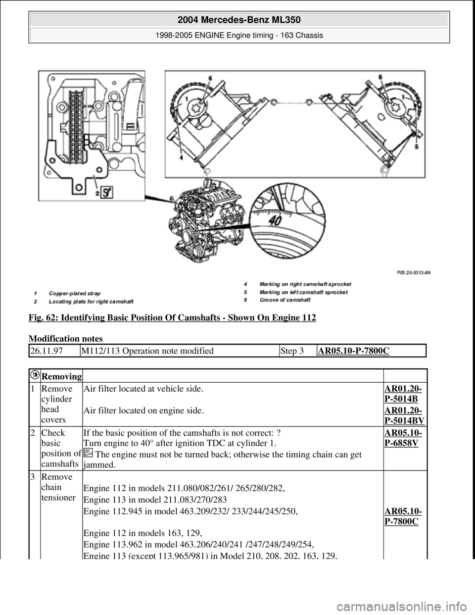
Fig. 62: Identifying Basic Position Of Camshafts - Shown On Engine 112
Modification notes
26.11.97M112/113 Operation note modifiedStep 3AR05.10-P-7800C
Removing
1Remove
cylinder
head
coversAir filter located at vehicle side.AR01.20-
P-5014B
Air filter located on engine side.AR01.20-
P-5014BV
2Check
basic
position o
f
camshafts
If the basic position of the camshafts is not correct: ?
Turn engine to 40° after ignition TDC at cylinder 1.
The engine must not be turned back; otherwise the timing chain can get
jammed.
AR05.10-
P-6858V
3Remove
chain
tensioner
Engine 112 in models 211.080/082/261/ 265/280/282,
Engine 113 in model 211.083/270/283
Engine 112.945 in model 463.209/232/ 233/244/245/250,AR05.10-
P-7800C
Engine 112 in models 163, 129,
Engine 113.962 in model 463.206/240/241 /247/248/249/254,
Engine 113 (except 113.965/981) in Model 210, 208, 202, 163, 129,
2004 Mercedes-Benz ML350
1998-2005 ENGINE Engine timing - 163 Chassis
me
Saturday, October 02, 2010 3:39:38 PMPage 58 © 2006 Mitchell Repair Information Company, LLC.
Page 2302 of 4133
Camshaft
Camshaft
tensionerEngine 112.945 in model 463.209/232/233 /244/245/250,AR05.10-
P-7800C
Engine 112 in models 163, 129
Engine 113.962 in model 463.206/240/241 /247/248/249/254,
Engine 113 (except 113.965/981) in Model 210, 208, 202, 163, 129,
Engine 113.982 in model 463.243/246
Engine 112 in Model 170, 202, 203, 208, 209, 210,AR05.10-
P-7800CA
Engine 113 in models 163.174/175, 209
Engine 112 in Model 211.061 /065, 220, 230.467,AR05.10-
P-
7800AM
Engine 113 in models 211.070/076/276,
215.373/374/375,220.070/073/074/075 /083/ 084/170/173/174/175/183/184/875,
230.474/475
Check
13Inspect
timing AR05.10-
P-6858V
Check
general
notes on
valve
timing,
scribe
marksEngine 112, 113AH05.10-
P-1000-
01A
The engine must not be turned back; otherwise the timing chain can get
jammed.
14Install
cylinder
head
coversAir filter located at vehicle side.AR01.20-
P-5014B
Air filter located on engine side.AR01.20-
P-5014BV
NumberDesignationEngines
113.940/941/
942/943/944/
948/961/962/
963/964/965/
966/967/968/
969/971/980/
981/982/984/
986/992/995Engine
112
except
112.951/976
BA05.20-P-
1001-01BBolt, camshaft
sprocketM12x45Stage 1Nm5050
Stage 2Angle°9090
2004 Mercedes-Benz ML350
1998-2005 ENGINE Engine timing - 163 Chassis
me
Saturday, October 02, 2010 3:39:38 PMPage 61 © 2006 Mitchell Repair Information Company, LLC.
Page 2308 of 4133
Camshaft
engine 113.990 /991
Model 209 except 209.475
Model 211 except
211.076 /261 /265 /270 /276
Model 463 with engine
113.962
Model 463 with engine
113.982
Model 211.076/276
Model 215.374,
220.074 /174AR15.10-P-2000RVK
Model 203 with engine 113
Model 171
Model 209.475
Model 211.261 /265/270AR15.10-P-2000AC
*BA15.10-P-1002-03A
13Install chain tensioner (2)Model 129, 463
Model 163 except
163.174/175
Model 202, 208, 210 with
engine 113AR05.10-P-7800C
Model 170, 202, 203, 208,
209, 210 with engine 112
Model 163.174/175
Model 209.375/475
Model 209.376/476 up to
23.4.04AR05.10-P-7800CA
Model 203 with engine 113
Model 209.376/476 as of
24.4.04AR05.10-P-7800AC
Model 211.0 with engine
112, 113
Model 211.276
Model 215
Model 220, 230 with engine
112, 113AR05.10-P-7800AM
Model 211.2 except 211.276
with engine 112, 113
Model 171 with engine 113
14Check engine valve
timing AR05.10-P-6858V
15Install cylinder head
coversAir filter mount ed on vehicleAR01.20-P-5014B
Air filter mounted on engineAR01.20-P-5014BV
2004 Mercedes-Benz ML350
1998-2005 ENGINE Engine timing - 163 Chassis
me
Saturday, October 02, 2010 3:39:38 PMPage 67 © 2006 Mitchell Repair Information Company, LLC.
Page 2315 of 4133
Fig. 77: Identifying Pl iers (606 589 00 37 00)
Fig. 78: Identifying Drift (119 589 00 43 00)
Engine 111, 271
Shown on engine 111
1. Use pliers (1) to pull of f valve stem seals (86)
2. Check surface of valve stems for roughness and format ion of burrs (visual inspection or with a nail).
Replace valves with a rough stem surface or formation of burrs.
3. Fit protective sleeve (2) onto valve stem.
4. Oil valve stem seals (86).
5. Press on the valve stem seal s (86) with a drift (3).
2004 Mercedes-Benz ML350
1998-2005 ENGINE Engine timing - 163 Chassis
me
Saturday, October 02, 2010 3:39:38 PMPage 74 © 2006 Mitchell Repair Information Company, LLC.
Page 2316 of 4133
Fig. 79: Identifying Replacem ent Of Valve Stem Seals - Shown On Engine 111
Engines 112, 113
Shown on Engine 112
1. Use pliers (1) to pull of f valve stem seals (86)
2. Check surface of valve stems for roughness and format ion of burrs (visual inspection or with a nail).
Replace valves with a rough stem surface or formation of burrs.
3. Fit protective sleeve (2) onto valve stem.
4. Oil valve stem seals (86).
5. Press on the valve stem seal s (86) with a drift (3).
2004 Mercedes-Benz ML350
1998-2005 ENGINE Engine timing - 163 Chassis
me
Saturday, October 02, 2010 3:39:38 PMPage 75 © 2006 Mitchell Repair Information Company, LLC.
Page 2321 of 4133
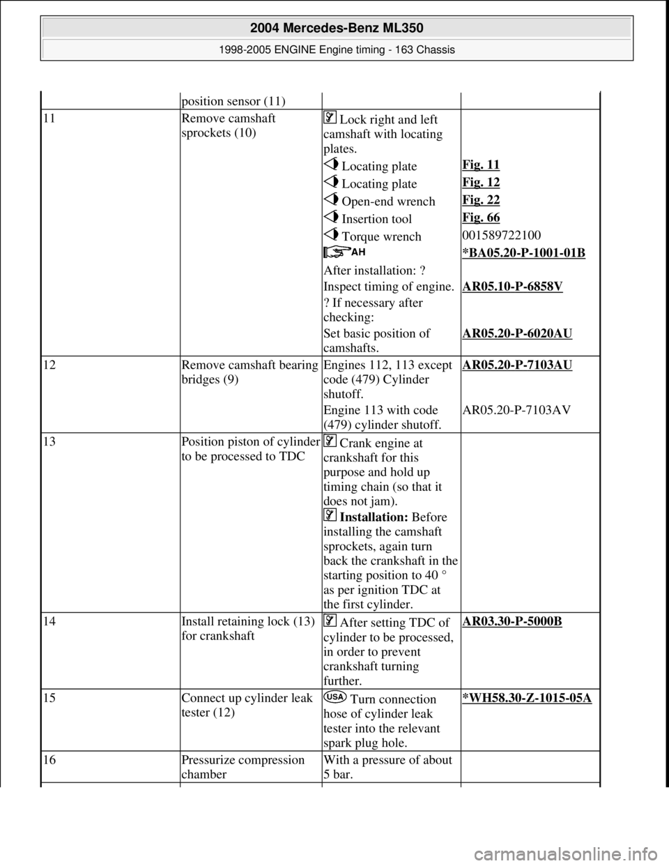
position sensor (11)
11Remove camshaft
sprockets (10) Lock right and left
camshaft with locating
plates.
Locating plateFig. 11
Locating plateFig. 12
Open-end wrenchFig. 22
Insertion toolFig. 66
Torque wrench001589722100
*BA05.20-P-1001-01B
After installation: ?
Inspect timing of engine.AR05.10-P-6858V
? If necessary after
checking:
Set basic position of
camshafts.AR05.20-P-6020AU
12Remove camsha ft bearing
bridges (9)Engines 112, 113 except
code (479) Cylinder
shutoff.AR05.20-P-7103AU
Engine 113 with code
(479) cylinder shutoff.AR05.20-P-7103AV
13Position piston of cylinder
to be processed to TDC Crank engine at
crankshaft for this
purpose and hold up
timing chain (so that it
does not jam).
Installation: Before
installing the camshaft
sprockets, again turn
back the crankshaft in the
starting position to 40 °
as per ignition TDC at
the first cylinder.
14Install retaining lock (13)
for crankshaft After setting TDC of
cylinder to be processed,
in order to prevent
crankshaft turning
further.AR03.30-P-5000B
15Connect up cylinder leak
tester (12) Turn connection
hose of cylinder leak
tester into the relevant
spark plug hole.*WH58.30-Z-1015-05A
16Pressurize compression
chamberWith a pressure of about
5 bar.
2004 Mercedes-Benz ML350
1998-2005 ENGINE Engine timing - 163 Chassis
me
Saturday, October 02, 2010 3:39:38 PMPage 80 © 2006 Mitchell Repair Information Company, LLC.
Page 2322 of 4133
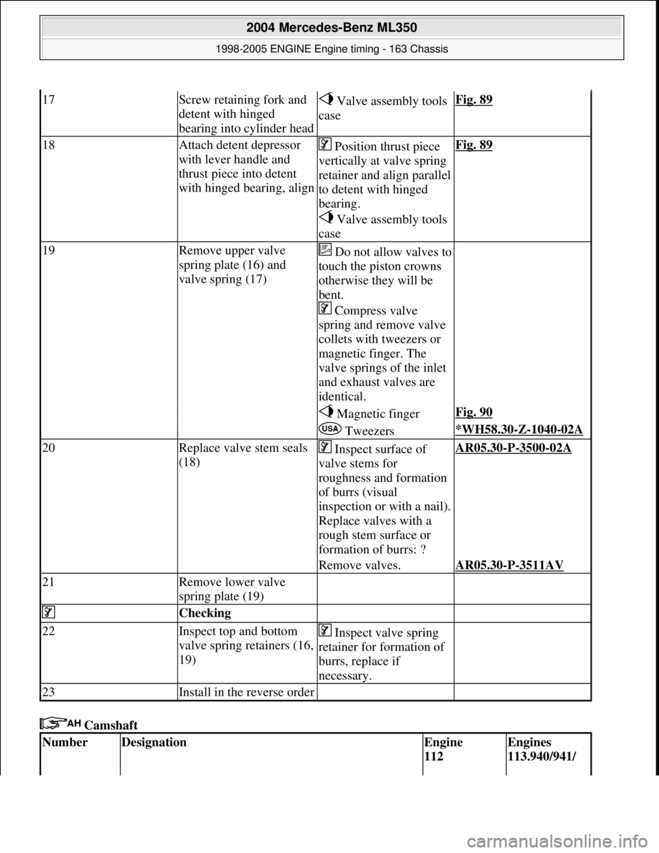
Camshaft
17Screw retaining fork and
detent with hinged
bearing into cylinder head Valve assembly tools
caseFig. 89
18Attach detent depressor
with lever handle and
thrust piece into detent
with hinged bearing, align Position thrust piece
vertically at valve spring
retainer and align parallel
to detent with hinged
bearing.
Valve assembly tools
caseFig. 89
19Remove upper valve
spring plate (16) and
valve spring (17)Do not allow valves to
touch the piston crowns
otherwise they will be
bent.
Compress valve
spring and remove valve
collets with tweezers or
magnetic finger. The
valve springs of the inlet
and exhaust valves are
identical.
Magnetic fingerFig. 90
Tweezers*WH58.30-Z-1040-02A
20Replace valve stem seals
(18) Inspect surface of
valve stems for
roughness and formation
of burrs (visual
inspection or with a nail).
Replace valves with a
rough stem surface or
formation of burrs: ?AR05.30-P-3500-02A
Remove valves.AR05.30-P-3511AV
21Remove lower valve
spring plate (19)
Checking
22Inspect top and bottom
valve spring retainers (16,
19) Inspect valve spring
retainer for formation of
burrs, replace if
necessary.
23Install in the reverse order
NumberDesignationEngine
112 Engines
113.940/941/
2004 Mercedes-Benz ML350
1998-2005 ENGINE Engine timing - 163 Chassis
me
Saturday, October 02, 2010 3:39:38 PMPage 81 © 2006 Mitchell Repair Information Company, LLC.