Page 53 of 1202
PP18S-01
PP-6
- PREPARATIONENGINE MECHANICAL
1996 TERCEL (RM440U)
EQUIPMENT
Caliper gauge
CO/HC meter
Compression gauge
Connecting rod aligner
Cylinder gauge
Dial indicator
Dye penetrant
Engine tune-up tester
Heater
Magnetic finger
Micromerer
OBD II scan toolIdle speed
Piston ring compressor
Piston ring expander
Plastigage
Precision straight edge
Soft brush
Spring testerValve spring
Steel squareValve spring
Torque wrench
Valve seat cutter
Vernier calipers
Page 138 of 1202

SS0N6-04
SS-8
- SERVICE SPECIFICATIONSENGINE MECHANICAL
1996 TERCEL (RM440U)
TORQUE SPECIFICATION
Part tightenedN´mkgf´cmft´lbf
Cylinder head cover x Cylinder head7.07061 in.´lbf
No. 2 idler pulley x Cylinder head2828020
Camshaft timing pulley x Camshaft5151037
No. 1 idler pulley x Cylinder block18.518513
Crankshaft pulley x Crankshaft1551,55011 2
No. 2 crankshaft pulley x Crankshaft pulley1919514
RH engine mounting insulator x RH engine mounting bracket6465047
RH engine mounting insulator x Body7374054
No. 1 engine hanger x Cylinder head2121015
No. 2 engine hanger x Cylinder head5353038
Cylinder head x Cylinder block 1st
2nd45
Turn 90°450
Turn 90°33
Turn 90°
Camshaft bearing cap x Cylinder head131309
Intake manifold x Cylinder head19.519514
Intake manifold stay x Intake manifold2020015
Intake manifold stay x Cylinder block2020015
Exhaust manifold x Cylinder head4848035
Exhaust manifold stay x Cylinder block4040029
Exhaust manifold stay x Exhaust manifold4040029
Exhaust manifold heat insulator x Exhaust manifold8.08069 in.´lbf
Water outlet housing x Cylinder head3030022
Camshaft position sensor x Cylinder head8.08069 in.´lbf
EGR VSV x Cylinder head17.517513
EGR valve x Cylinder head17.517513
EGR pipe x EGR valve4040029
EGR pipe x Intake manifold3030022
PS ump bracket x Cylinder head4344032
Fuel inlet hose x Fuel filter2930022
Front exhaust pipe x Exhaust manifold6263049
Connecting rod cap x Connecting rod4040029
Crankshaft bearing cap x Cylinder block5858042
Rear oil seal retainer x Cylinder block7.57565 in.´lbf
Oil filter union x Cylinder block2525018
Oil pressure switch x Cylinder block131309
RH engine mounting bracket x Cylinder block5959043
Knock sensor x Cylinder block4545033
Generator bracket x Cylinder block2424018
Rear end plate x Cylinder block101007
Flywheel x Crankshaft9090065
Drive plate x Crankshaft9090065
Drive plate x Torque converter clutch2525018
A/C compressor bracket x Cylinder block2728020
PS pump adjusting strut x Cylinder block2121015
Page 494 of 1202

EM3445
EM9405
EM3447
Plastigage
EM3448
EM3449
EM-72
- ENGINE MECHANICALCYLINDER BLOCK
1996 TERCEL (RM440U)
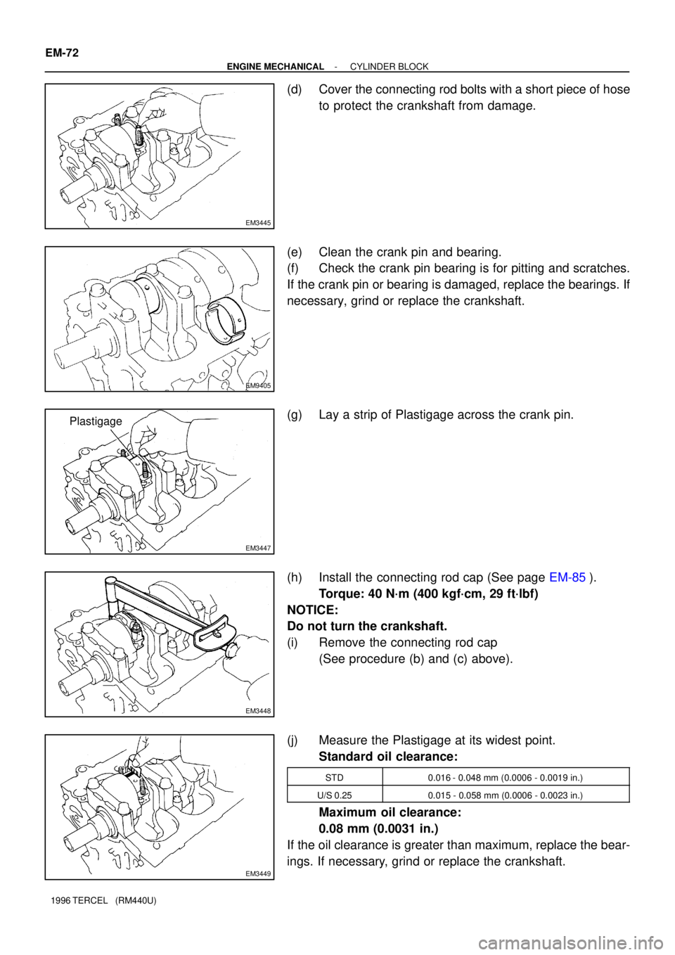
(d) Cover the connecting rod bolts with a short piece of hose
to protect the crankshaft from damage.
(e) Clean the crank pin and bearing.
(f) Check the crank pin bearing is for pitting and scratches.
If the crank pin or bearing is damaged, replace the bearings. If
necessary, grind or replace the crankshaft.
(g) Lay a strip of Plastigage across the crank pin.
(h) Install the connecting rod cap (See page EM-85).
Torque: 40 N´m (400 kgf´cm, 29 ft´lbf)
NOTICE:
Do not turn the crankshaft.
(i) Remove the connecting rod cap
(See procedure (b) and (c) above).
(j) Measure the Plastigage at its widest point.
Standard oil clearance:
STD0.016 - 0.048 mm (0.0006 - 0.0019 in.)
U/S 0.250.015 - 0.058 mm (0.0006 - 0.0023 in.)
Maximum oil clearance:
0.08 mm (0.0031 in.)
If the oil clearance is greater than maximum, replace the bear-
ings. If necessary, grind or replace the crankshaft.
Page 509 of 1202

P20551
P20530
Front
Z14291
1
2 3
45
6
7
89
10
EM3480
P20569
Front Mark
(Cavity)
FrontPush
- ENGINE MECHANICALCYLINDER BLOCK
EM-87
1996 TERCEL (RM440U)
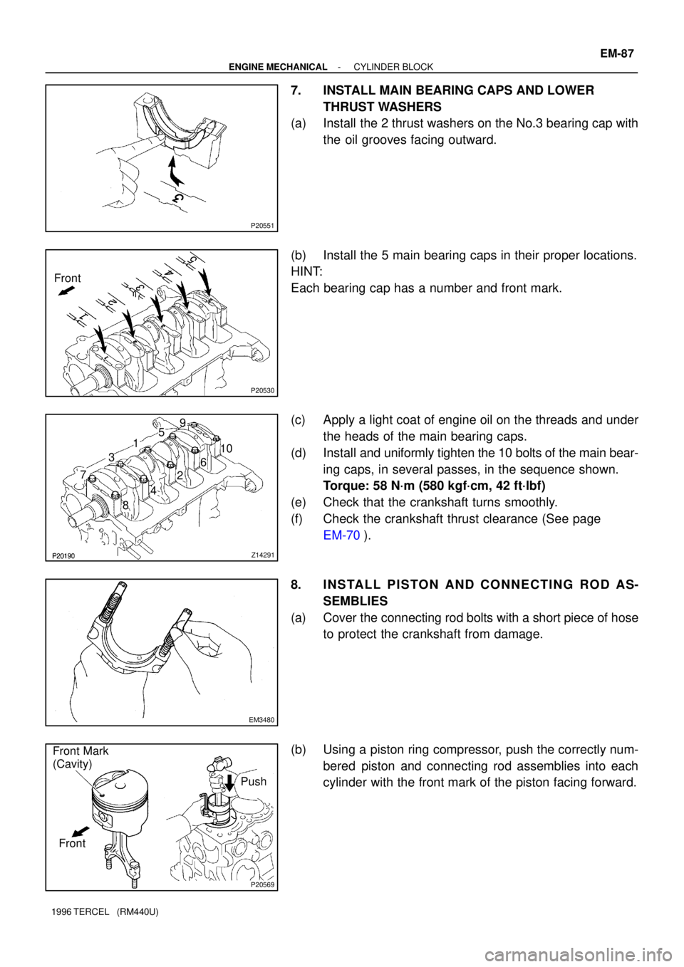
7. INSTALL MAIN BEARING CAPS AND LOWER
THRUST WASHERS
(a) Install the 2 thrust washers on the No.3 bearing cap with
the oil grooves facing outward.
(b) Install the 5 main bearing caps in their proper locations.
HINT:
Each bearing cap has a number and front mark.
(c) Apply a light coat of engine oil on the threads and under
the heads of the main bearing caps.
(d) Install and uniformly tighten the 10 bolts of the main bear-
ing caps, in several passes, in the sequence shown.
Torque: 58 N´m (580 kgf´cm, 42 ft´lbf)
(e) Check that the crankshaft turns smoothly.
(f) Check the crankshaft thrust clearance (See page
EM-70).
8. INSTALL PISTON AND CONNECTING ROD AS-
SEMBLIES
(a) Cover the connecting rod bolts with a short piece of hose
to protect the crankshaft from damage.
(b) Using a piston ring compressor, push the correctly num-
bered piston and connecting rod assemblies into each
cylinder with the front mark of the piston facing forward.
Page 510 of 1202

EM3481
Front Mark
(Protrusion)
Front
EM3448
P20475
Seal Packing
A'B'
A
B
A - A' B - B' EM-88
- ENGINE MECHANICALCYLINDER BLOCK
1996 TERCEL (RM440U)
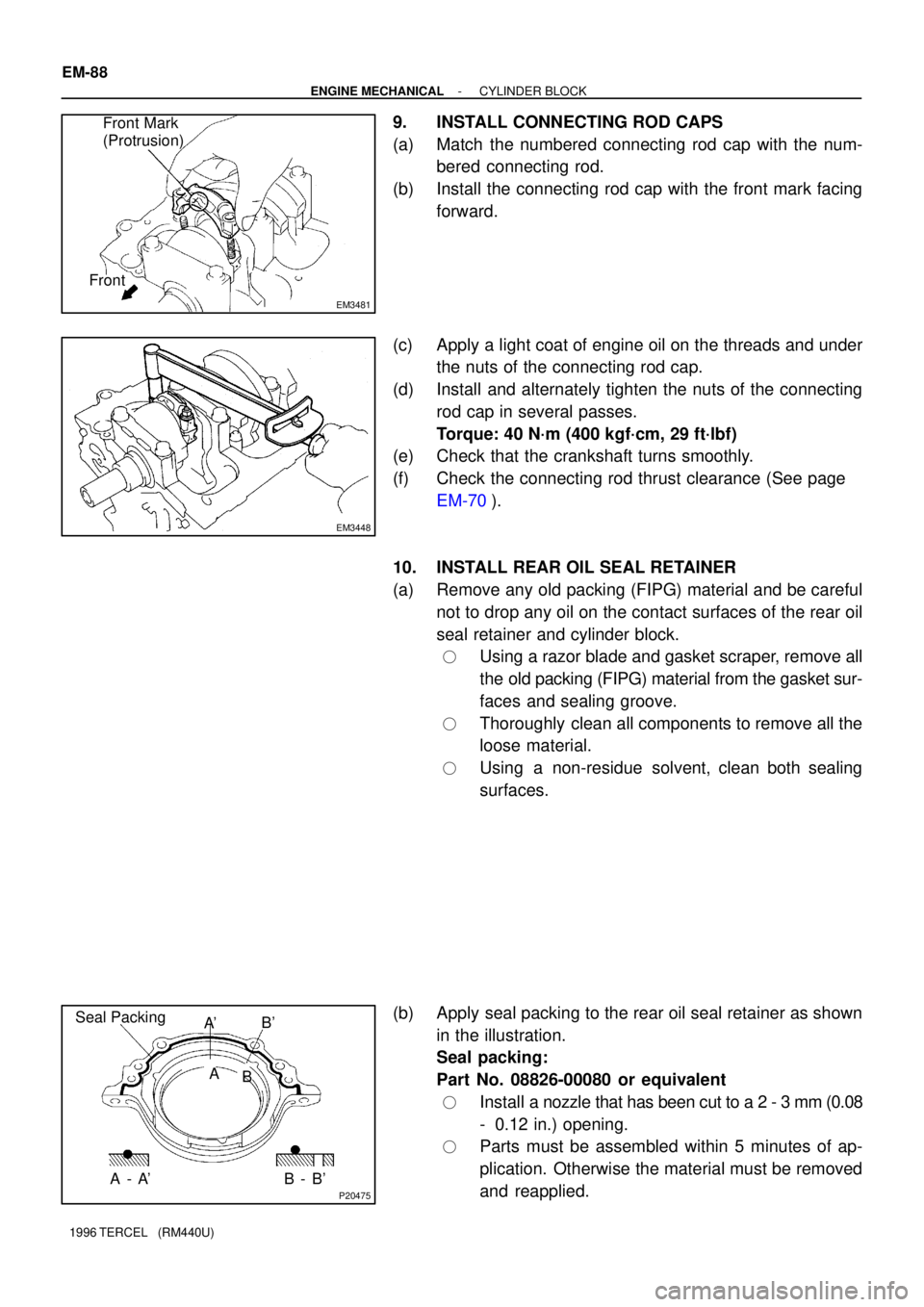
9. INSTALL CONNECTING ROD CAPS
(a) Match the numbered connecting rod cap with the num-
bered connecting rod.
(b) Install the connecting rod cap with the front mark facing
forward.
(c) Apply a light coat of engine oil on the threads and under
the nuts of the connecting rod cap.
(d) Install and alternately tighten the nuts of the connecting
rod cap in several passes.
Torque: 40 N´m (400 kgf´cm, 29 ft´lbf)
(e) Check that the crankshaft turns smoothly.
(f) Check the connecting rod thrust clearance (See page
EM-70).
10. INSTALL REAR OIL SEAL RETAINER
(a) Remove any old packing (FIPG) material and be careful
not to drop any oil on the contact surfaces of the rear oil
seal retainer and cylinder block.
�Using a razor blade and gasket scraper, remove all
the old packing (FIPG) material from the gasket sur-
faces and sealing groove.
�Thoroughly clean all components to remove all the
loose material.
�Using a non-residue solvent, clean both sealing
surfaces.
(b) Apply seal packing to the rear oil seal retainer as shown
in the illustration.
Seal packing:
Part No. 08826-00080 or equivalent
�Install a nozzle that has been cut to a 2 - 3 mm (0.08
- 0.12 in.) opening.
�Parts must be assembled within 5 minutes of ap-
plication. Otherwise the material must be removed
and reapplied.
Page 800 of 1202
AT3328
Z15031
B
B
A
C
A AA
B
OR0038
AT5616
AT2713
- AUTOMATIC TRANSAXLE (A242L)VALVE BODY ASSEMBLY
AX-17
799 Author�: Date�:
1996 TERCEL (RM440U)
6. REMOVE MANUAL DETENT SPRING
Remove the bolt and detent spring.
Torque: 10 N´m (100 kgf´cm, 7 ft´lbf)
HINT:
Check that the manual valve lever is in contact with the center
of the roller at the tip of the detent spring.
7. DISCONNECT SOLENOID CONNECTOR
8. REMOVE VALVE BODY
(a) Remove the 12 bolts.
Bolt length:
A: 20 mm (0.79 in.)
B: 30 mm (1.18 in.)
C: 55 mm (2.17 in.)
Torque: 10 N´m (100 kgf´cm, 7 ft´lbf)
(b) Disconnect the throttle cable.
NOTICE:
Be careful not to entangle the kick-down switch and sole-
noid wire.
(c) Disconnect the manual valve connecting rod.
(d) Remove the valve body.
9. REMOVE 2ND BRAKE APPLY GASKET
HINT:
Replace the used gasket with a new one.
Page 835 of 1202

SA128-02
FA1535
SST
F03986
SA-18
- SUSPENSION AND AXLEFRONT DRIVE SHAFT
1996 TERCEL (RM440U)
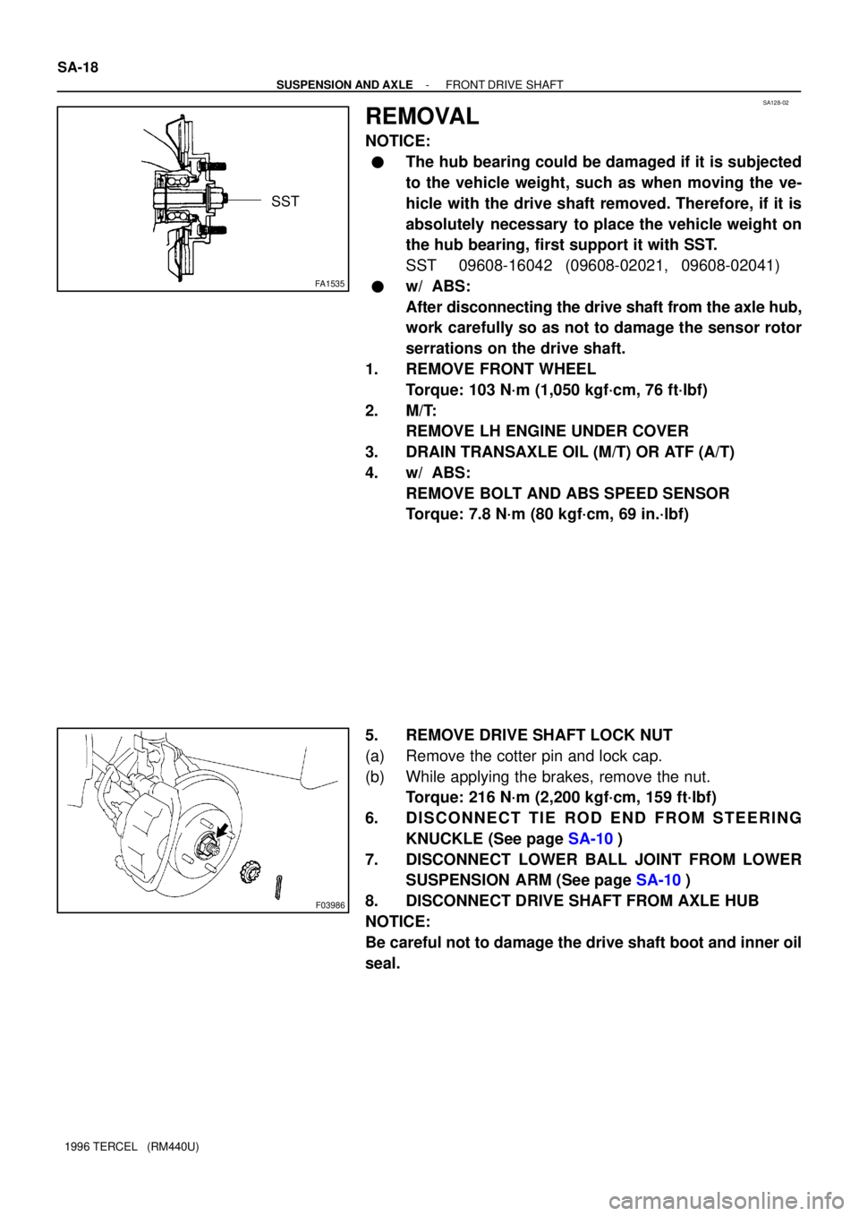
REMOVAL
NOTICE:
�The hub bearing could be damaged if it is subjected
to the vehicle weight, such as when moving the ve-
hicle with the drive shaft removed. Therefore, if it is
absolutely necessary to place the vehicle weight on
the hub bearing, first support it with SST.
SST 09608-16042 (09608-02021, 09608-02041)
�w/ ABS:
After disconnecting the drive shaft from the axle hub,
work carefully so as not to damage the sensor rotor
serrations on the drive shaft.
1. REMOVE FRONT WHEEL
Torque: 103 N´m (1,050 kgf´cm, 76 ft´lbf)
2. M/T:
REMOVE LH ENGINE UNDER COVER
3. DRAIN TRANSAXLE OIL (M/T) OR ATF (A/T)
4. w/ ABS:
REMOVE BOLT AND ABS SPEED SENSOR
Torque: 7.8 N´m (80 kgf´cm, 69 in.´lbf)
5. REMOVE DRIVE SHAFT LOCK NUT
(a) Remove the cotter pin and lock cap.
(b) While applying the brakes, remove the nut.
Torque: 216 N´m (2,200 kgf´cm, 159 ft´lbf)
6. DISCONNECT TIE ROD END FROM STEERING
KNUCKLE (See page SA-10)
7. DISCONNECT LOWER BALL JOINT FROM LOWER
SUSPENSION ARM (See page SA-10)
8. DISCONNECT DRIVE SHAFT FROM AXLE HUB
NOTICE:
Be careful not to damage the drive shaft boot and inner oil
seal.