Page 76 of 1202
PP19D-01
- PREPARATIONCHARGING
PP-29
76 Author�: Date�:
1996 TERCEL (RM440U)
CHARGING
SST (Special Service Tools)
09285-76010Injection Pump Camshaft Bearing
Cone ReplacerRotor rear bearing cover
09286-4601 1Injection Pump Spline Shaft
PullerRectifier end frame
09950-60010Replacer Set
(09951-00460)Replacer 46Rotor front bearing
09820-00021Alternator Rear Bearing Puller
09820-00030Alternator Rear Bearing ReplacerRotor rear bearing
09820-63010Alternator Pulley Set Nut Wrench
Set
Page 77 of 1202
PP3IU-01
PP-30
- PREPARATIONCHARGING
1996 TERCEL (RM440U)
RECOMMENDED TOOLS
09082-00040TOYOTA Electrical Tester.
09200-00010Engine Adjust Kit .
09905-00013Snap Ring Pliers .Generator washer
Page 78 of 1202
PP19F-01
- PREPARATIONCHARGING
PP-31
1996 TERCEL (RM440U)
EQUIPMENT
Battery specific gravity gauge
Belt tension gauge
Torque wrench
Vernier calipersRotor (Slip ring), Brush
Page 127 of 1202
PP17B-01
PP-80
- PREPARATIONAIR CONDITIONING
127 Author�: Date�:
1996 TERCEL (RM440U)
AIR CONDITIONING
SST (Special Service Tools)
07110-58060Air Conditioner Service Tool Set
(07117-58060)Refrigerant Drain Service Valve
(07117-58070)T-Joint
(07117-58080)Quick Disconnect AdapterDischarge (diam. 16 mm)
(07117-58090)Quick Disconnect AdapterSuction (diam. 13 mm)
(07117-78050)Refrigerant Charging Gauge
(07117-88060)Refrigerant Charging HoseDischarge (Red)
(07117-88070)Refrigerant Charging HoseSuction (Blue)
(07117-88080)Refrigerant Charging HoseUtility (Green)
07112-66040Magnetic Clutch Remover
07112-76050Magnetic Clutch Stopper
07114-84020Snap Ring Pliers
Page 151 of 1202
SS0NH-03
- SERVICE SPECIFICATIONSCHARGING
SS-21
151 Author�: Date�:
1996 TERCEL (RM440U)
CHARGING
SERVICE DATA
BatterySpecific gravity at 20°C (68°F)1.25 - 1.29
Drive beltTension New belt
Used belt160 ± 20 lbf
100 ± 20 lbf
GeneratorRated output
Rotor coil resistance
Type A at 20°C (68°F)
Type B at 20°C (68°F)
Slip ring diameter STD
Minimum
Brush exposed length STD
Minimum12 V 70 A, 60 A
2.2 - 2.4 W
2.8 - 3.0 W
14.2 - 14.4 mm (0.559 - 0.567 in.)
12.8 mm (0.504 in.)
10.5 mm (0.413 in.)
1.5 mm (0.059 in.)
Voltage regulatorRegulating voltage at 25°C (77°F)
at 115°C (239°F)13.9 - 15.1 V
13.5 - 14.3 V
Page 152 of 1202
SS0NI-03
SS-22
- SERVICE SPECIFICATIONSCHARGING
1996 TERCEL (RM440U)
TORQUE SPECIFICATION
Part tightenedN´mkgf´cmft´lbf
Generator x Generator bracket4142030
Generator x Adjusting lever121209
Bearing retainer x Drive end frame2.62723 in.´lbf
Rectifier end frame x Drive end frame Type A, B4.54640 in.´lbf
Generator pulley x Rotor11 01,12581
Rectifier holder x Coil lead on rectifier end frame Type A, B1.962017 in.´lbf
Rear end cover x Rectifier holder Type A, B4.44540 in.´lbf
Terminal insulator x Rectifier holder4.14236 in.´lbf
Page 308 of 1202
BE6653R14671F06870
ON
GND
IG1
(-) (+)
F07208
GND (-) (+) LOCK
- DIAGNOSTICSANTI-LOCK BRAKE SYSTEM
DI-133
1996 TERCEL (RM440U)
INSPECTION PROCEDURE
1 Check battery positive voltage.
OK:
Voltage: 10 - 14 V
NG Check and repair charging system.
OK
2 Check voltage between terminals IG1 and GND of ABS ECU connector.
PREPARATION:
Disconnect the ABS ECU with connectors still connected.
CHECK:
(a) Turn the ignition switch ON.
(b) Measure the voltage between terminals IG1 and GND of
the ABS ECU connector.
OK:
Voltage: 10 - 14 V
NG Check and repair ABS ECU.
OK
3 Check continuity between terminal GND of ECU connector and body ground.
CHECK:
Measure the resistance between terminal GND of the ABS ECU
connector and body ground.
OK:
Resistance: 1 W or less
OK Repair or replace harness or connector.
NG
Page 347 of 1202

R14285 AB0119H00021
Airbag Sensor Assembly ON
IG2 ACC
(+) (-)
DI-172
- DIAGNOSTICSSUPPLEMENTAL RESTRAINT SYSTEM
1996 TERCEL (RM440U)
DTC 31 Airbag Sensor Assembly Malfunction
CIRCUIT DESCRIPTION
The airbag sensor assembly consists of a airbag sensor, safing sensor, drive circuit, diagnosis circuit and
ignition control, etc.
It receives signals from the airbag sensor, judges whether or not the SRS must be activated, and diagnostic
system malfunction.
DTC 31 is recorded when occurrence of a malfunction in the airbag sensor assembly is detected.
DTC No.DTC Detection ConditionTrouble Area
31�Airbag sensor assembly malfunction�Airbag sensor assembly
INSPECTION PROCEDURE
HINT:
When a malfunction code other than code 31 is displayed at the same time, first repair the malfunction indi-
cated by the malfunction code other than code 31.
1 Preparation (See step 1 on page DI-177)
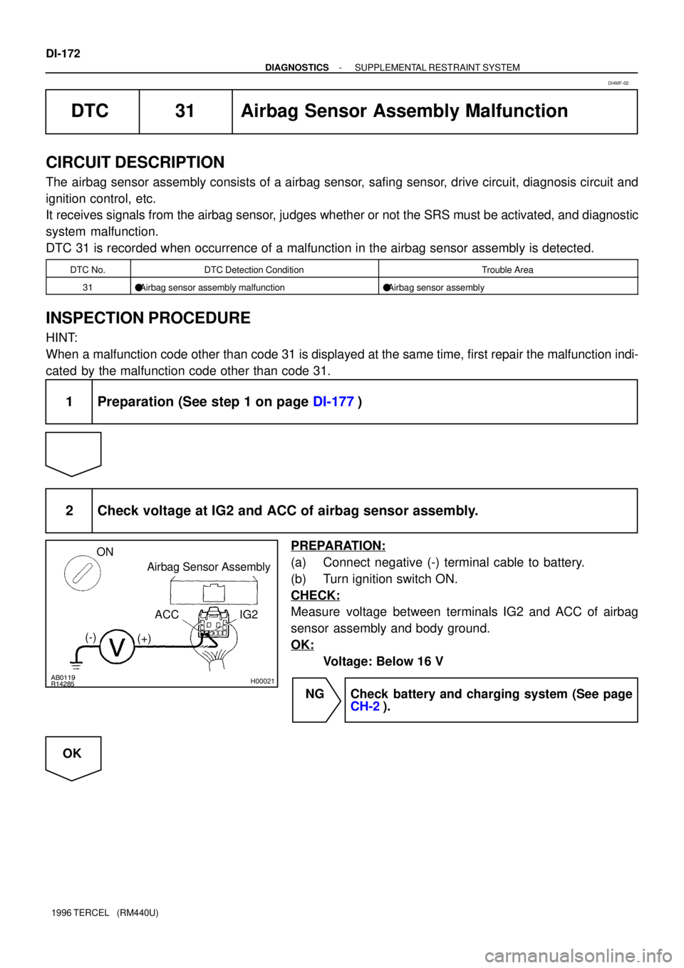
2 Check voltage at IG2 and ACC of airbag sensor assembly.
PREPARATION:
(a) Connect negative (-) terminal cable to battery.
(b) Turn ignition switch ON.
CHECK:
Measure voltage between terminals IG2 and ACC of airbag
sensor assembly and body ground.
OK:
Voltage: Below 16 V
NG Check battery and charging system (See page
CH-2).
OK
DI4MF-02