Page 313 of 1202
W00708
A6 L
Battery 2Motor
RelayABS ECU
R-L W-BL
L
A7
A7
1
6
A7
A7
4
A75 1
3
A6
Solenoid
Relay
ABS ECU
ABS ECU W-B
W-B
EA
ABS Control Relay
DLC1
22
EB
ABS ActuatorEA110 13IC2 1E
Y
23
Short Pin
A5
4
ABS ECU Y
EA1R-L R-L
R-LR-L
R-L
1 Driver Side J/B
C7
C8 7
GAUGE
Light ABS Warning 1
3
ABS ECU
A1218
WA12 V
L-R DI-138
- DIAGNOSTICSANTI-LOCK BRAKE SYSTEM
1996 TERCEL (RM440U)
ABS Warning Light Circuit
CIRCUIT DESCRIPTION
If the ECU detects trouble, it lights the ABS warning light while at the same time prohibiting ABS control. At
this time, the ECU records a DTC in memory.
After removing the short pin of the DLC1, connect between terminals Tc and E
1 of the DLC1 to make the
ABS warning light blink and output the DTC.
WIRING DIAGRAM
DI4LZ-02
Page 314 of 1202
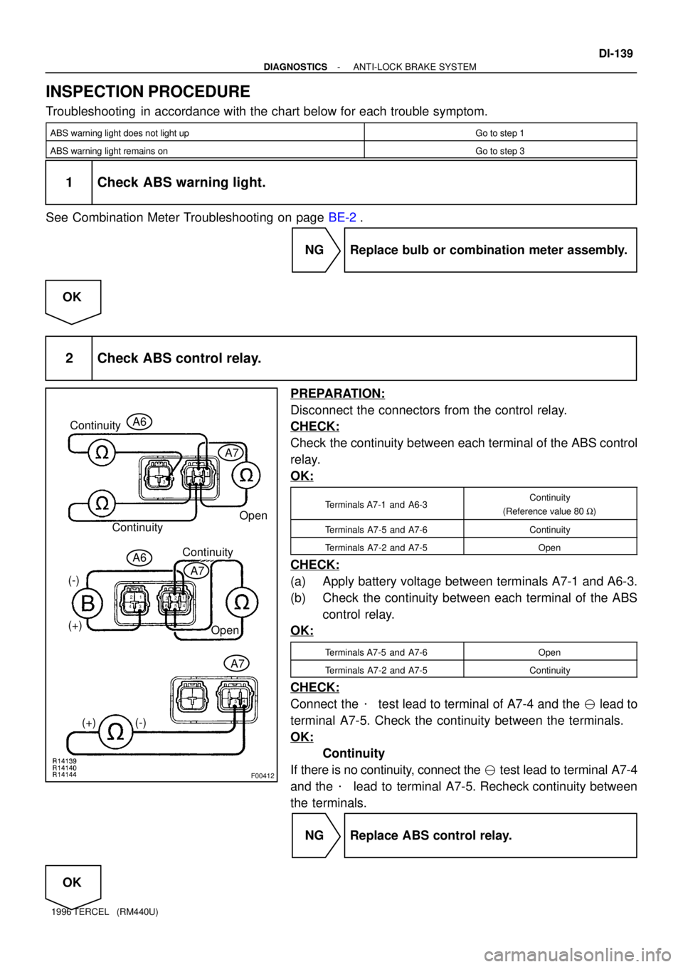
F00412
Continuity
Open A6
A7
(-)
(+)
1
62
3
45
Continuity
1
62
5 3 1 2
3 4
4 5
A7
A6Continuity
Open
(+) (-)A7
- DIAGNOSTICSANTI-LOCK BRAKE SYSTEM
DI-139
1996 TERCEL (RM440U)
INSPECTION PROCEDURE
Troubleshooting in accordance with the chart below for each trouble symptom.
ABS warning light does not light upGo to step 1
ABS warning light remains onGo to step 3
1 Check ABS warning light.
See Combination Meter Troubleshooting on page BE-2.
NG Replace bulb or combination meter assembly.
OK
2 Check ABS control relay.
PREPARATION:
Disconnect the connectors from the control relay.
CHECK:
Check the continuity between each terminal of the ABS control
relay.
OK:
Terminals A7-1 and A6-3Continuity
(Reference value 80 W)
Terminals A7-5 and A7-6Continuity
Terminals A7-2 and A7-5Open
CHECK:
(a) Apply battery voltage between terminals A7-1 and A6-3.
(b) Check the continuity between each terminal of the ABS
control relay.
OK:
Terminals A7-5 and A7-6Open
Terminals A7-2 and A7-5Continuity
CHECK:
Connect the � test lead to terminal of A7-4 and the � lead to
terminal A7-5. Check the continuity between the terminals.
OK:
Continuity
If there is no continuity, connect the � test lead to terminal A7-4
and the � lead to terminal A7-5. Recheck continuity between
the terminals.
NG Replace ABS control relay.
OK
Page 315 of 1202
DI-140
- DIAGNOSTICSANTI-LOCK BRAKE SYSTEM
1996 TERCEL (RM440U)
Repair or replace and check for open in harness and connector between DLC1 and ABS control
relay and body ground (See page IN-26).
3 Is DTC output?
Check DTC on page DI-1 11.
YES Repair circuit indicated by code output.
NO
4 Does ABS warning light go off if short pin is removed?
NO Check for short in harness and connector be-
tween warning light and DLC1 and ECU (See
page IN-26).
YES
5 Check ABS control relay (See step 2).
NG Replace ABS control relay.
OK
Repair or replace and check for short in harness and connector between DLC1 and ABS control
relay (See page IN-26).
Page 367 of 1202
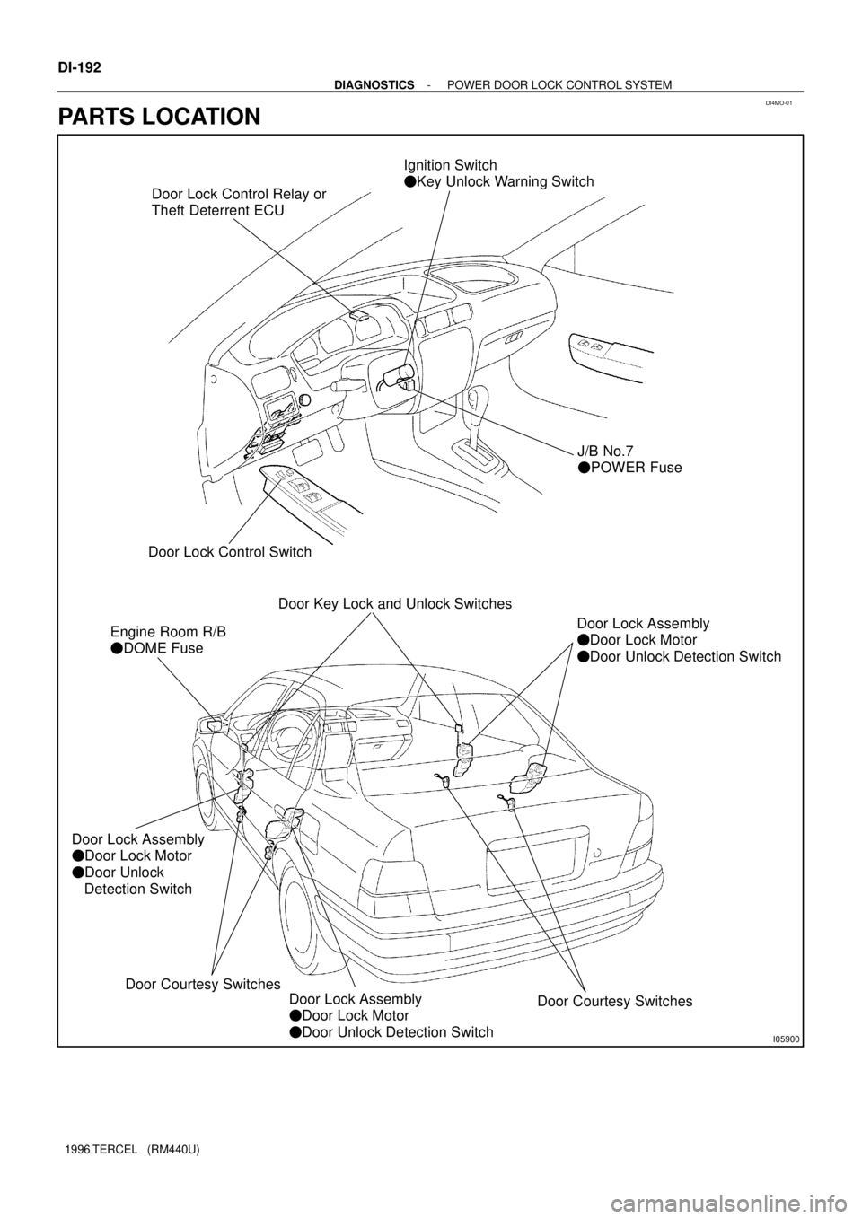
DI4MO-01
I05900
Door Lock Control Relay or
Theft Deterrent ECUIgnition Switch
� Key Unlock Warning Switch
J/B No.7
� POWER Fuse
Door Lock Control Switch
Door Key Lock and Unlock Switches
Engine Room R/B
� DOME Fuse
Door Lock Assembly
� Door Lock Motor
� Door Unlock Detection SwitchDoor Courtesy Switches
Door Lock Assembly
� Door Lock Motor
� Door Unlock Detection Switch
Door Lock Assembly
� Door Lock Motor
� Door Unlock
Detection Switch
Door Courtesy Switches DI-192
- DIAGNOSTICSPOWER DOOR LOCK CONTROL SYSTEM
1996 TERCEL (RM440U)
PARTS LOCATION
Page 370 of 1202
I05883Door Lock Control Relay
T6
- DIAGNOSTICSPOWER DOOR LOCK CONTROL SYSTEM
DI-195
1996 TERCEL (RM440U)
w/o Theft Deterrent System
TerminalsSymbolsConditionSTD Value
3 e 4ACT(-) - ACT(+)Ignition switch ºOFFº.Below 50 W
8 e GroundB - GroundAlways.10 - 14 V
916UL3 E
Door key lock and unlock switch ºUNLOCKº.
(Driver's)Below 1 W
9 e 16UL3 - EDoor key lock and unlock switch ºOFFº or ºLOCKº.
(Driver's)1 MW or higher
1016L1 E
Door lock control switch ºLOCKº and
door key lock and unlock switch ºLOCKº .Below 1 W
10 e 16L1 - EDoor lock control switch ºOFFº or ºUNLOCKº and door key
lock and unlock switch ºOFFº or ºUNLOCKº.1 MW or higher
1116UL1 EDoor lock control switch ºUNLOCKº .Below 1 W11 e 16UL1 - EDoor lock control switch ºOFFº or ºLOCKº.1 MW or higher
16 e GroundE - GroundAlways.Below 1 W
Page 371 of 1202
DI4MQ-01
DI-196
- DIAGNOSTICSPOWER DOOR LOCK CONTROL SYSTEM
1996 TERCEL (RM440U)
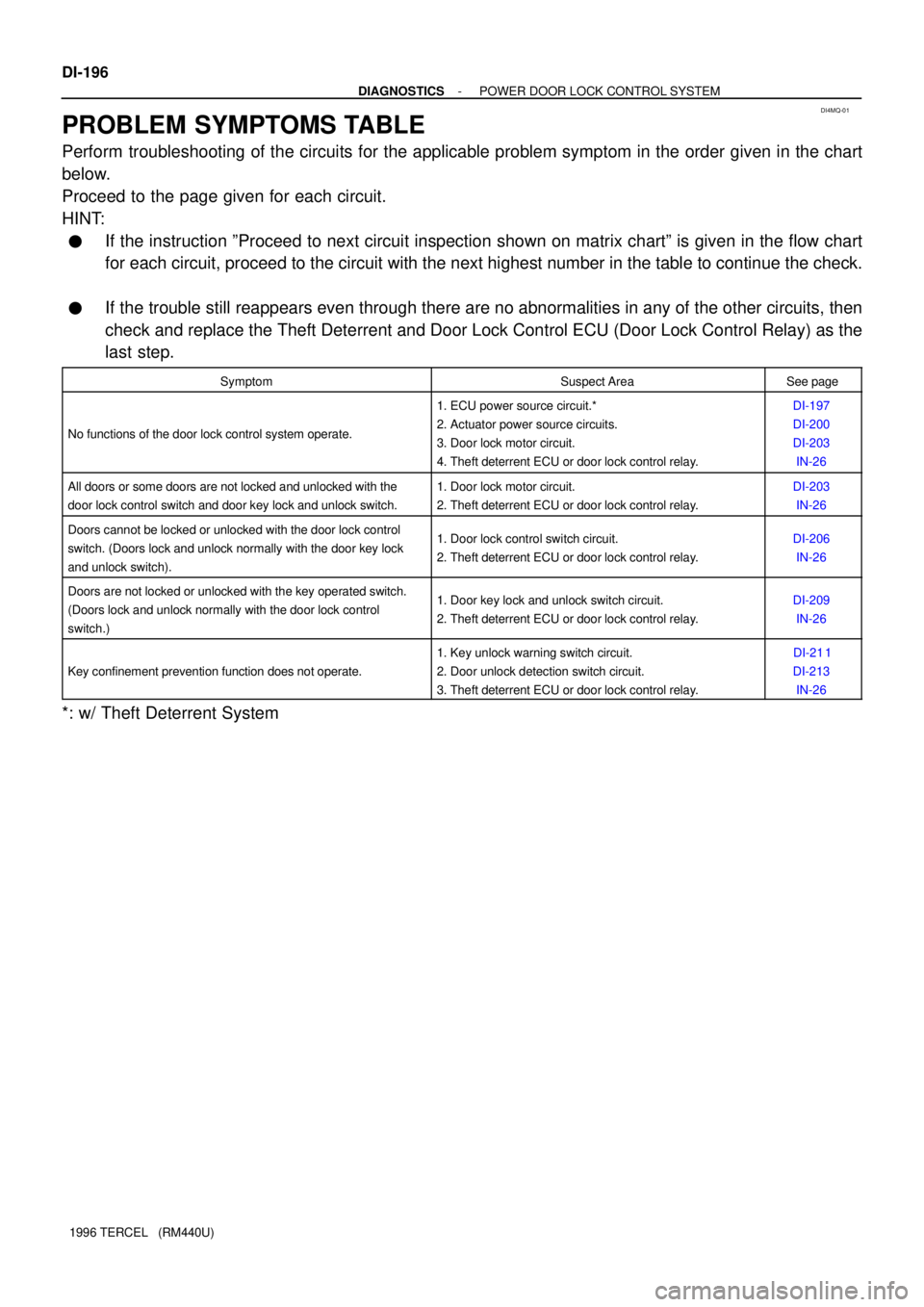
PROBLEM SYMPTOMS TABLE
Perform troubleshooting of the circuits for the applicable problem symptom in the order given in the chart
below.
Proceed to the page given for each circuit.
HINT:
�If the instruction ºProceed to next circuit inspection shown on matrix chartº is given in the flow chart
for each circuit, proceed to the circuit with the next highest number in the table to continue the check.
�If the trouble still reappears even through there are no abnormalities in any of the other circuits, then
check and replace the Theft Deterrent and Door Lock Control ECU (Door Lock Control Relay) as the
last step.
SymptomSuspect AreaSee page
No functions of the door lock control system operate.
1. ECU power source circuit.*
2. Actuator power source circuits.
3. Door lock motor circuit.
4. Theft deterrent ECU or door lock control relay.DI-197
DI-200
DI-203
IN-26
All doors or some doors are not locked and unlocked with the
door lock control switch and door key lock and unlock switch.1. Door lock motor circuit.
2. Theft deterrent ECU or door lock control relay.DI-203
IN-26
Doors cannot be locked or unlocked with the door lock control
switch. (Doors lock and unlock normally with the door key lock
and unlock switch).1. Door lock control switch circuit.
2. Theft deterrent ECU or door lock control relay.DI-206
IN-26
Doors are not locked or unlocked with the key operated switch.
(Doors lock and unlock normally with the door lock control
switch.)1. Door key lock and unlock switch circuit.
2. Theft deterrent ECU or door lock control relay.DI-209
IN-26
Key confinement prevention function does not operate.
1. Key unlock warning switch circuit.
2. Door unlock detection switch circuit.
3. Theft deterrent ECU or door lock control relay.DI-21 1
DI-213
IN-26
*: w/ Theft Deterrent System
Page 372 of 1202
DI4MR-02
N20816
BatteryEngine Room
Relay BlockInstrument Panel
Junction BlockTheft Deterrent ECU
+B1
T41
1D8
1K11
L-Y L-Y
2
MAIN FL
EA2BDOME 1
- DIAGNOSTICSPOWER DOOR LOCK CONTROL SYSTEM
DI-197
1996 TERCEL (RM440U)
CIRCUIT INSPECTION
ECU Power Source Circuit (w / Theft deterrent System)
CIRCUIT DESCRIPTION
This circuit provides power to operate the theft deterrent and door lock ECU.
WIRING DIAGRAM
Page 373 of 1202
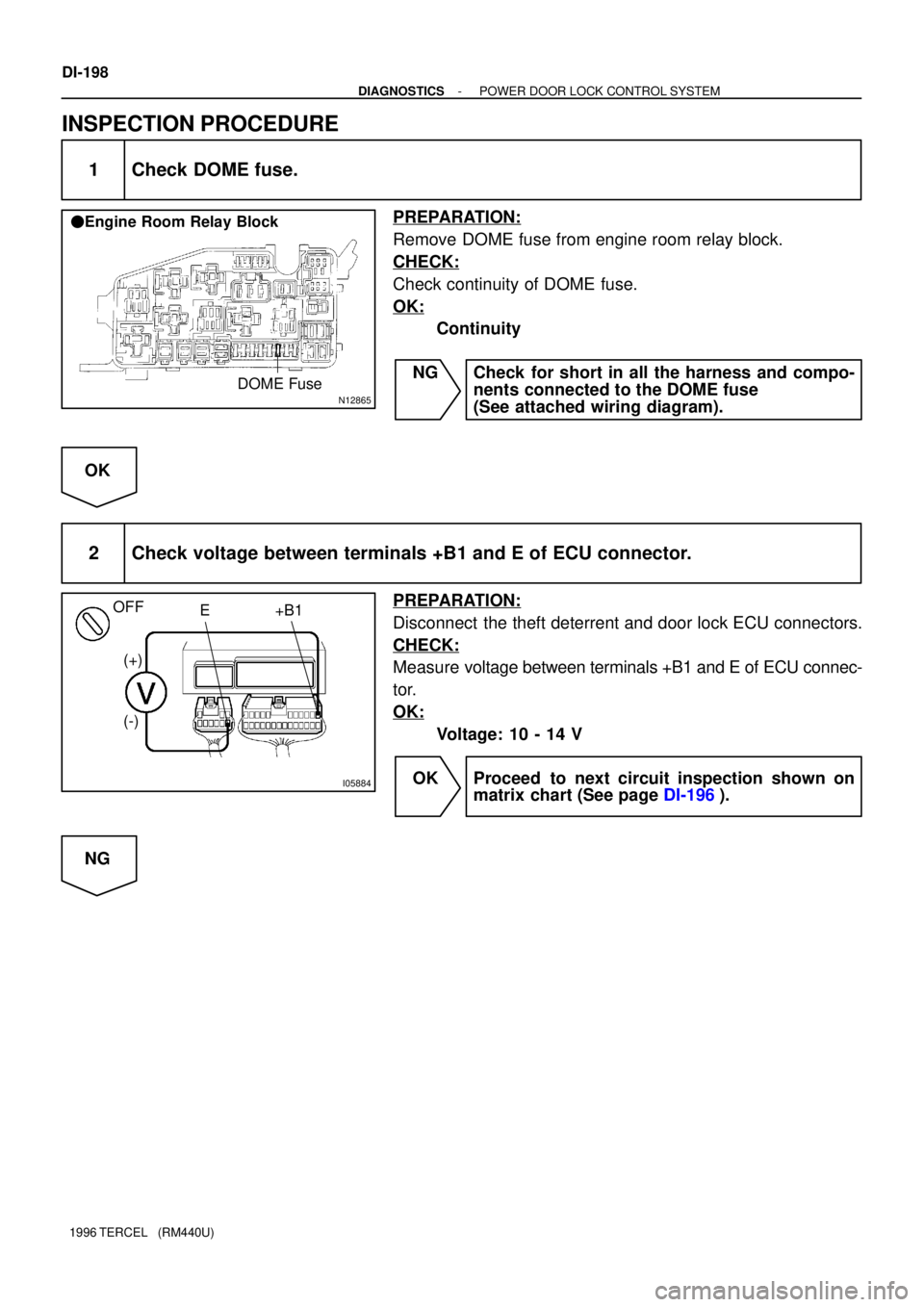
N12865DOME Fuse
� Engine Room Relay Block
I05884
(+)
(-)E +B1
OFF
DI-198
- DIAGNOSTICSPOWER DOOR LOCK CONTROL SYSTEM
1996 TERCEL (RM440U)
INSPECTION PROCEDURE
1 Check DOME fuse.
PREPARATION:
Remove DOME fuse from engine room relay block.
CHECK:
Check continuity of DOME fuse.
OK:
Continuity
NG Check for short in all the harness and compo-
nents connected to the DOME fuse
(See attached wiring diagram).
OK
2 Check voltage between terminals +B1 and E of ECU connector.
PREPARATION:
Disconnect the theft deterrent and door lock ECU connectors.
CHECK:
Measure voltage between terminals +B1 and E of ECU connec-
tor.
OK:
Voltage: 10 - 14 V
OK Proceed to next circuit inspection shown on
matrix chart (See page DI-196).
NG