Page 406 of 1202
N20820
BatteryMAIN FL
B1
EA2 HAZ-HORN
2 W2Engine Room Relay Block
Horn Relay
11
2
2IC1G-Y24
T4
G-R
1
HORNTheft Deterrent ECU
HORN
H4 G-Y
B
- DIAGNOSTICSTHEFT DETERRENT SYSTEM
DI-231
1996 TERCEL (RM440U)
Horn Relay Circuit
CIRCUIT DESCRIPTION
When the theft deterrent system is activated, it causes the Tr in the ECU to switch on and off in approximately
0.4 sec. cycles. This switches the horn relay on and off, thus the horns blow (See the wiring diagram below).
In this condition, if any of the following operations is done, the Tr in the ECU goes off and the horn relay
switches off, thus stopping the horns from blowing:
(1) Unlock the front LH or RH door with key.
(2) Turn the ignition switch to ACC or ON position.
(3) Unlock the doors with the wireless door lock control system.
(4) Wait for approximately 60 seconds.
WIRING DIAGRAM
DI4N7-01
Page 407 of 1202
BE4061I05892I09777
HORN
(+) (-)OFF
Disconnect
DI-232
- DIAGNOSTICSTHEFT DETERRENT SYSTEM
1996 TERCEL (RM440U)
INSPECTION PROCEDURE
HINT:
The flow chart below is based on the premise that the horns blow normally whenever the horn switch is oper-
ated.
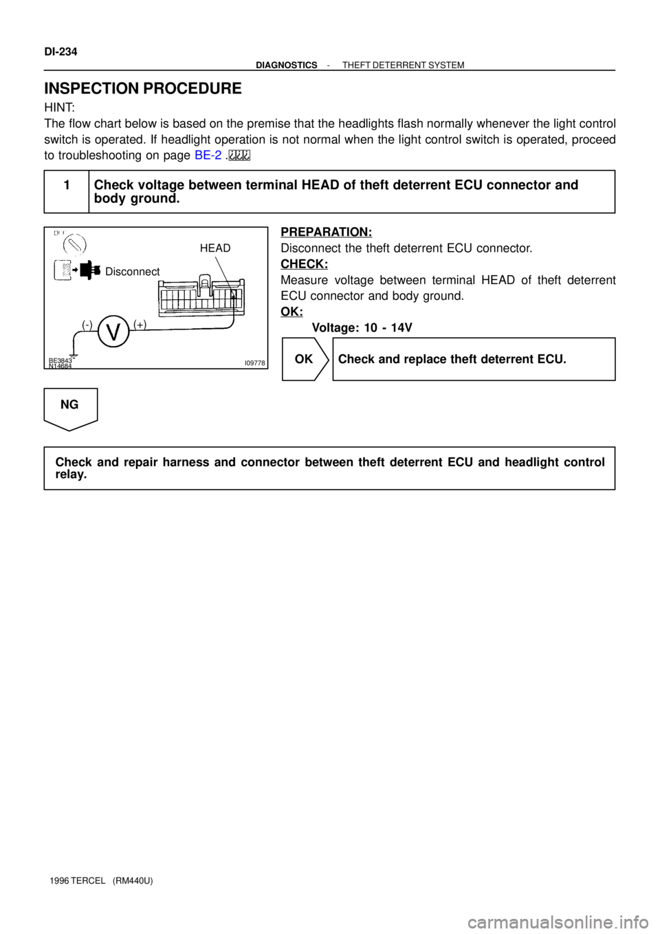
1 Check voltage between terminal HORN of theft deterrent ECU connector and
body ground.
PREPARATION:
Disconnect the theft deterrent ECU connectors.
CHECK:
Measure voltage between terminal HORN of theft deterrent
ECU connector and body ground.
OK:
Voltage: 10~14V
OK Check and replace theft deterrent ECU.
NG
Check and repair harness and connector between theft deterrent ECU and horn relay.
Page 408 of 1202
N20821
BatteryHeadlight
LHHeadlight
RH MAIN FL B 1
EA2
R
R-L2
2HEAD LH
HEAD RH2 B-R Engine Room Relay Block
Headlight Control Relay
2
2R-L
IC1
16
Light Control
Switch
(Combination
Switch)
13R-L R-L10
T4 Theft Deterrent ECU
HEAD
C12
- DIAGNOSTICSTHEFT DETERRENT SYSTEM
DI-233
1996 TERCEL (RM440U)
Headlight Control Relay Circuit
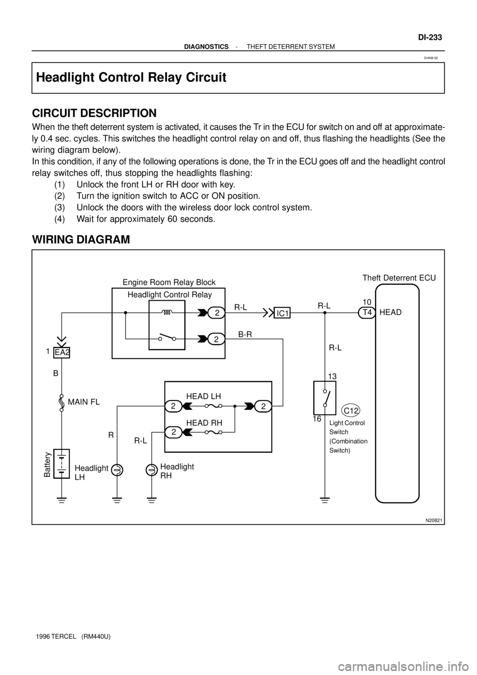
CIRCUIT DESCRIPTION
When the theft deterrent system is activated, it causes the Tr in the ECU for switch on and off at approximate-
ly 0.4 sec. cycles. This switches the headlight control relay on and off, thus flashing the headlights (See the
wiring diagram below).
In this condition, if any of the following operations is done, the Tr in the ECU goes off and the headlight control
relay switches off, thus stopping the headlights flashing:
(1) Unlock the front LH or RH door with key.
(2) Turn the ignition switch to ACC or ON position.
(3) Unlock the doors with the wireless door lock control system.
(4) Wait for approximately 60 seconds.
WIRING DIAGRAM
DI4N8-02
Page 409 of 1202
BE3843N14684I09778
HEAD
(-)(+)
Disconnect
DI-234
- DIAGNOSTICSTHEFT DETERRENT SYSTEM
1996 TERCEL (RM440U)
INSPECTION PROCEDURE
HINT:
The flow chart below is based on the premise that the headlights flash normally whenever the light control
switch is operated. If headlight operation is not normal when the light control switch is operated, proceed
to troubleshooting on page BE-2.
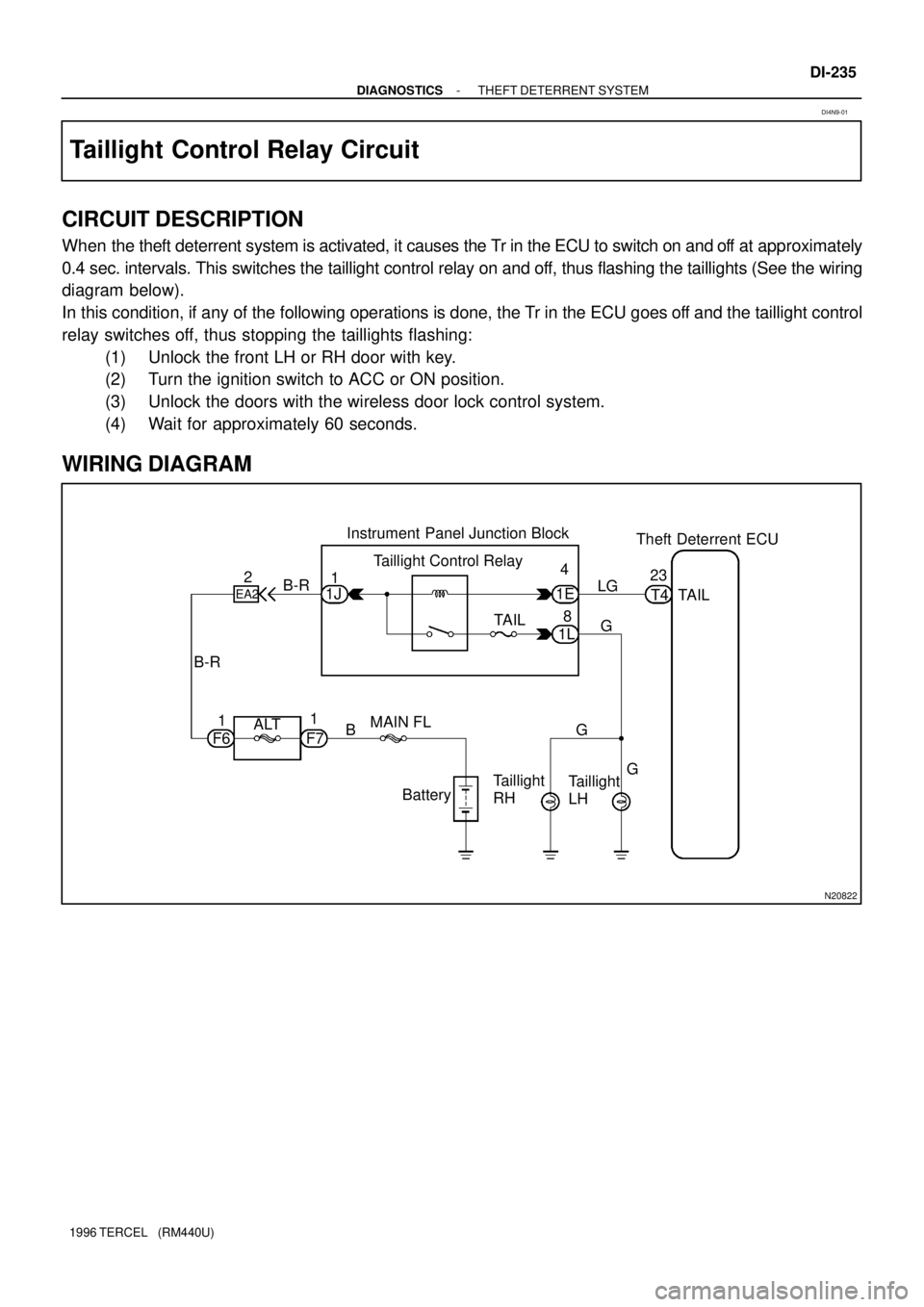
1 Check voltage between terminal HEAD of theft deterrent ECU connector and
body ground.
PREPARATION:
Disconnect the theft deterrent ECU connector.
CHECK:
Measure voltage between terminal HEAD of theft deterrent
ECU connector and body ground.
OK:
Voltage: 10 - 14V
OK Check and replace theft deterrent ECU.
NG
Check and repair harness and connector between theft deterrent ECU and headlight control
relay.
Page 410 of 1202
N20822
Battery MAIN FL 1
F6 F7ALT B-R
Taillight
LH Taillight
RH 2
EA2B-R
G 1J1Instrument Panel Junction Block
Taillight Control Relay
TAIL4
1E
8
1L
G G LGTheft Deterrent ECU
23
T4 TAIL
1
B
- DIAGNOSTICSTHEFT DETERRENT SYSTEM
DI-235
1996 TERCEL (RM440U)
Taillight Control Relay Circuit
CIRCUIT DESCRIPTION
When the theft deterrent system is activated, it causes the Tr in the ECU to switch on and off at approximately
0.4 sec. intervals. This switches the taillight control relay on and off, thus flashing the taillights (See the wiring
diagram below).
In this condition, if any of the following operations is done, the Tr in the ECU goes off and the taillight control
relay switches off, thus stopping the taillights flashing:
(1) Unlock the front LH or RH door with key.
(2) Turn the ignition switch to ACC or ON position.
(3) Unlock the doors with the wireless door lock control system.
(4) Wait for approximately 60 seconds.
WIRING DIAGRAM
DI4N9-01
Page 411 of 1202
BE3843N14685I09779
TAIL (-)
(+)
Disconnect
DI-236
- DIAGNOSTICSTHEFT DETERRENT SYSTEM
1996 TERCEL (RM440U)
INSPECTION PROCEDURE
HINT:
The flow chart below is based on the premise that the taillights light up normally whenever the light control
switch is operated. If taillight operation is not normal when the light control switch is operated, proceed to
troubleshooting on page BE-2.
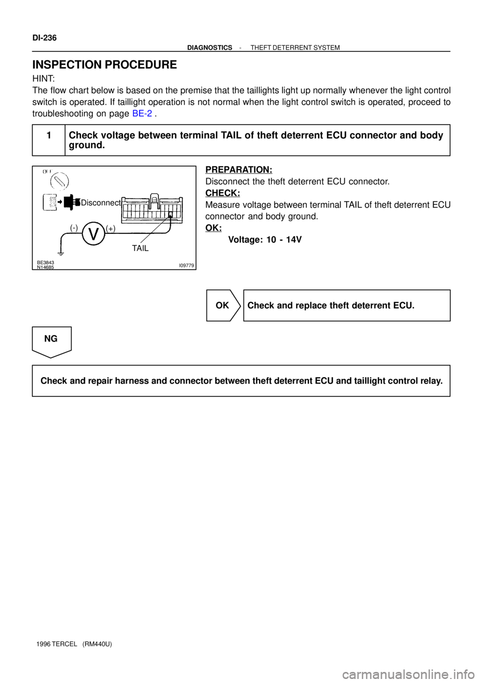
1 Check voltage between terminal TAIL of theft deterrent ECU connector and body
ground.
PREPARATION:
Disconnect the theft deterrent ECU connector.
CHECK:
Measure voltage between terminal TAIL of theft deterrent ECU
connector and body ground.
OK:
Voltage: 10 - 14V
OK Check and replace theft deterrent ECU.
NG
Check and repair harness and connector between theft deterrent ECU and taillight control relay.
Page 421 of 1202
N12897
EB W-BEngine Room
Relay Block
(JUNCTION CONNECTOR)A
A
2 2Engine Hood
Courtesy Switch
12
LG-B12
IC2
LG-B14
T4 Theft Deterrent ECU
DSWH
E5
W-B DI-246
- DIAGNOSTICSTHEFT DETERRENT SYSTEM
1996 TERCEL (RM440U)
Engine Hood Courtesy Switch Circuit
CIRCUIT DESCRIPTION
The engine hood courtesy switch is built into the engine hood lock assembly and goes on when the engine
hood is opened and goes off when the engine hood is closed.
WIRING DIAGRAM
DI4NE-02
Page 530 of 1202
P19552
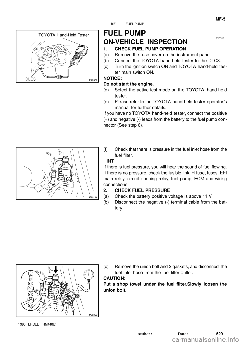
TOYOTA Hand-Held Tester
DLC3
P20392
SF1PR-02
P20176
P20391
- MFIFUEL PUMP
MF-5
529 Author�: Date�:
1996 TERCEL (RM440U)
FUEL PUMP
ON-VEHICLE INSPECTION
1. CHECK FUEL PUMP OPERATION
(a) Remove the fuse cover on the instrument panel.
(b) Connect the TOYOTA hand-held tester to the DLC3.
(c) Turn the ignition switch ON and TOYOTA hand-held tes-
ter main switch ON.
NOTICE:
Do not start the engine.
(d) Select the active test mode on the TOYOTA hand-held
tester.
(e) Please refer to the TOYOTA hand-held tester operator's
manual for further details.
If you have no TOYOTA hand-held tester, connect the positive
(+) and negative (-) leads from the battery to the fuel pump con-
nector (See step 6).
(f) Check that there is pressure in the fuel inlet hose from the
fuel filter.
HINT:
If there is fuel pressure, you will hear the sound of fuel flowing.
If there is no pressure, check the fusible link, H-fuse, fuses, EFI
main relay, circuit opening relay, fuel pump, ECM and wiring
connections.
2. CHECK FUEL PRESSURE
(a) Check the battery positive voltage is above 11 V.
(b) Disconnect the negative (-) terminal cable from the bat-
tery.
(c) Remove the union bolt and 2 gaskets, and disconnect the
fuel inlet hose from the fuel filter outlet.
CAUTION:
Put a shop towel under the fuel filter.Slowly loosen the
union bolt.