Page 375 of 1202
N20817
BatteryInstrument Panel
Junction BlockTheft Deterrent ECU
(Door Lock Control Relay)
1J2
W-G
MAIN FLEA2
F7 F6 221A3
D6 (8)
T39
D6 (16)
T34
A A
IEJ3
JUNCTION
CONNECTOR A
AW-B
ALT AM1POWER
2 1L
W-B B W-G
( ): w/o Theft Deterrent System+B2
(B)
E
B-R B-R2JUNCTION
CONNECTOR J6
J/B No.2
11J/B No.7 DI-200
- DIAGNOSTICSPOWER DOOR LOCK CONTROL SYSTEM
1996 TERCEL (RM440U)
Actuator Power Source Circuit
CIRCUIT DESCRIPTION
This circuit provides power to drive the door lock motor.
WIRING DIAGRAM
DI4MS-01
Page 376 of 1202
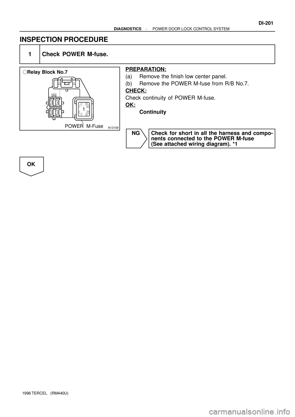
N13109
� Relay Block No.7
POWER M-Fuse
1
- DIAGNOSTICSPOWER DOOR LOCK CONTROL SYSTEM
DI-201
1996 TERCEL (RM440U)
INSPECTION PROCEDURE
1 Check POWER M-fuse.
PREPARATION:
(a) Remove the finish low center panel.
(b) Remove the POWER M-fuse from R/B No.7.
CHECK:
Check continuity of POWER M-fuse.
OK:
Continuity
NG Check for short in all the harness and compo-
nents connected to the POWER M-fuse
(See attached wiring diagram). *1
OK
Page 378 of 1202
N12882
ID1
IH1
BJ1
BK1Theft Deterrent ECU
(Door Lock Control Relay)
( ): w/o Theft Deterrent System JUNCTION
CONNECTOR B R
GC
8 IE8 5 4
4 2T3 D63 (4)
T3 D62 (3) J6
JUNCTION
CONNECTOR
C
GG
G
G
GG
G
GC
CACT+
ACT-
B
BID2
IH1
BJ1
BK1 5 4
4 2 Door Lock Motor
Driver's
Rear Left Passenger's
Rear Right R
R
RR
R
R
R IE1
14
R 7
9
2
21
8
6
6
- DIAGNOSTICSPOWER DOOR LOCK CONTROL SYSTEM
DI-203
1996 TERCEL (RM440U)
Door Lock Motor Circuit
CIRCUIT DESCRIPTION
This door lock motor locks and unlocks the door in accordance with signals from the ECU.
WIRING DIAGRAM
DI4MT-02
Page 381 of 1202
N15259
Theft Deterrent ECU
(Door Lock Control Relay)
Door Lock Control Switch
Driver's
(Door Lock Control Switch
Passenger's)
( ): w/o Theft Deterrent System IEJ6
JUNCTION
CONNECTORID110
W-B
A
IH13 ID11D9 (10)
T45
D9 (11)
T48L1
UL1 ID12
IH12 LOCK
UNLOCK
LOCK
UNLOCK AA W-B
W-B
W-B
W-B IH1 12
J3
JUNCTION
CONNECTOR A
A1 2
4
3
(3)
(2)R-Y
G-Y
R-Y
G-YR-Y
G-Y
R-Y
G-Y (4) DI-206
- DIAGNOSTICSPOWER DOOR LOCK CONTROL SYSTEM
1996 TERCEL (RM440U)
Door Lock Control Switch Circuit
CIRCUIT DESCRIPTION
When the door lock control switch is pushed to the lock side, Lock terminal of the switch is grounded, and
when the switch is pushed to the unlock side, Unlock terminal is grounded (See wiring diagram below).
WIRING DIAGRAM
DI4MU-02
Page 394 of 1202
DI4N1-01
N12446N12538I10188
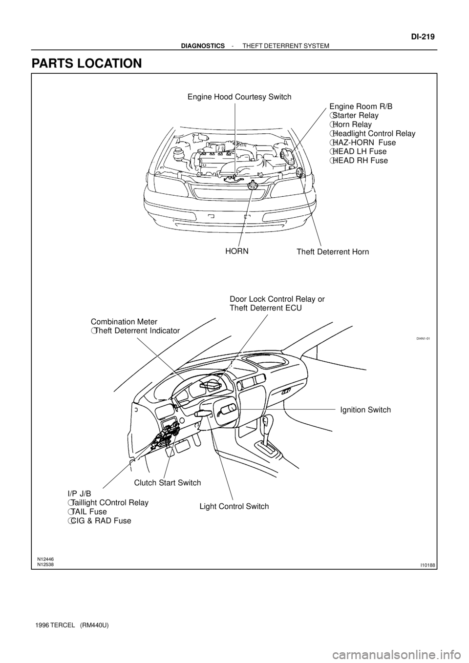
Engine Hood Courtesy Switch
Engine Room R/B
�Starter Relay
�Horn Relay
�Headlight Control Relay
�HAZ-HORN Fuse
�HEAD LH Fuse
�HEAD RH Fuse
Theft Deterrent Horn HORN
Door Lock Control Relay or
Theft Deterrent ECU
Combination Meter
�Theft Deterrent Indicator
Ignition Switch
Light Control Switch Clutch Start Switch
I/P J/B
�Taillight COntrol Relay
�TAIL Fuse
�CIG & RAD Fuse
- DIAGNOSTICSTHEFT DETERRENT SYSTEM
DI-219
1996 TERCEL (RM440U)
PARTS LOCATION
Page 398 of 1202
DI4N3-01
Details of Problem
The theft deterrent system cannot be set
Inspecting Circuit*1See page
DI-224 1. Indicator light circuit
4. Door courtesy switch circuit
5. Door unlock detection switch circuit
6. Engine hood courtesy switch circuit
The indicator light does not blink when system is setIndicator light circuit
When the
system is
set
When the rear door is unlocked
When the luggage compartment door is opened
by a method other than the key2. Luggage compartment door key
lock and unlock switch circuit
3. Luggage compartment door
courtesy switch circuit
When the engine hood is opened
The system
does not
operateDoor unlock detection switch circuit
Luggage compartment door
courtesy switch circuit
Engine hood courtesy switch circuit
While the system is
in warning operation
Horns do not sound
Theft deterrent horn does not sound
Headlights do not flash
Taillights do not flash
The starter cut is not cut off
The rear door lock is not locked in unlock conditionHorn relay circuit
Theft deterrent horn circuit
Headlight control relay circuit
Taillight control relay circuit
Starter relay circuit
Door unlock detection switch circuit
It is not canceled when the ignition key is turned to
ACC or ON position
It still operates when the luggage compartment door is
opened with the key When the
system is
setIgnition switch circuit
Luggage compartment door key
lock and unlock switch circuit
System is still set even when a rear door is open Door courtesy switch circuit
Even when the
system is not
setHorns sound
Theft deterrent horn sounds
Headlights stay on
Taillights stay onHorn relay circuit
Theft deterrent horn circuit
Headlight control relay circuit
Taillight control relay circuit
DI-241
DI-239
DI-244
DI-213
DI-246
DI-224
DI-213
DI-239
DI-246
DI-231
DI-228
DI-233
DI-235
DI-226
DI-213
DI-237
DI-241
DI-244
DI-231
DI-228
DI-233
DI-235
*1: If numbers are given to the circuit, proceed with troubleshooting in the order indicated by those numbers.
- DIAGNOSTICSTHEFT DETERRENT SYSTEM
DI-223
1996 TERCEL (RM440U)
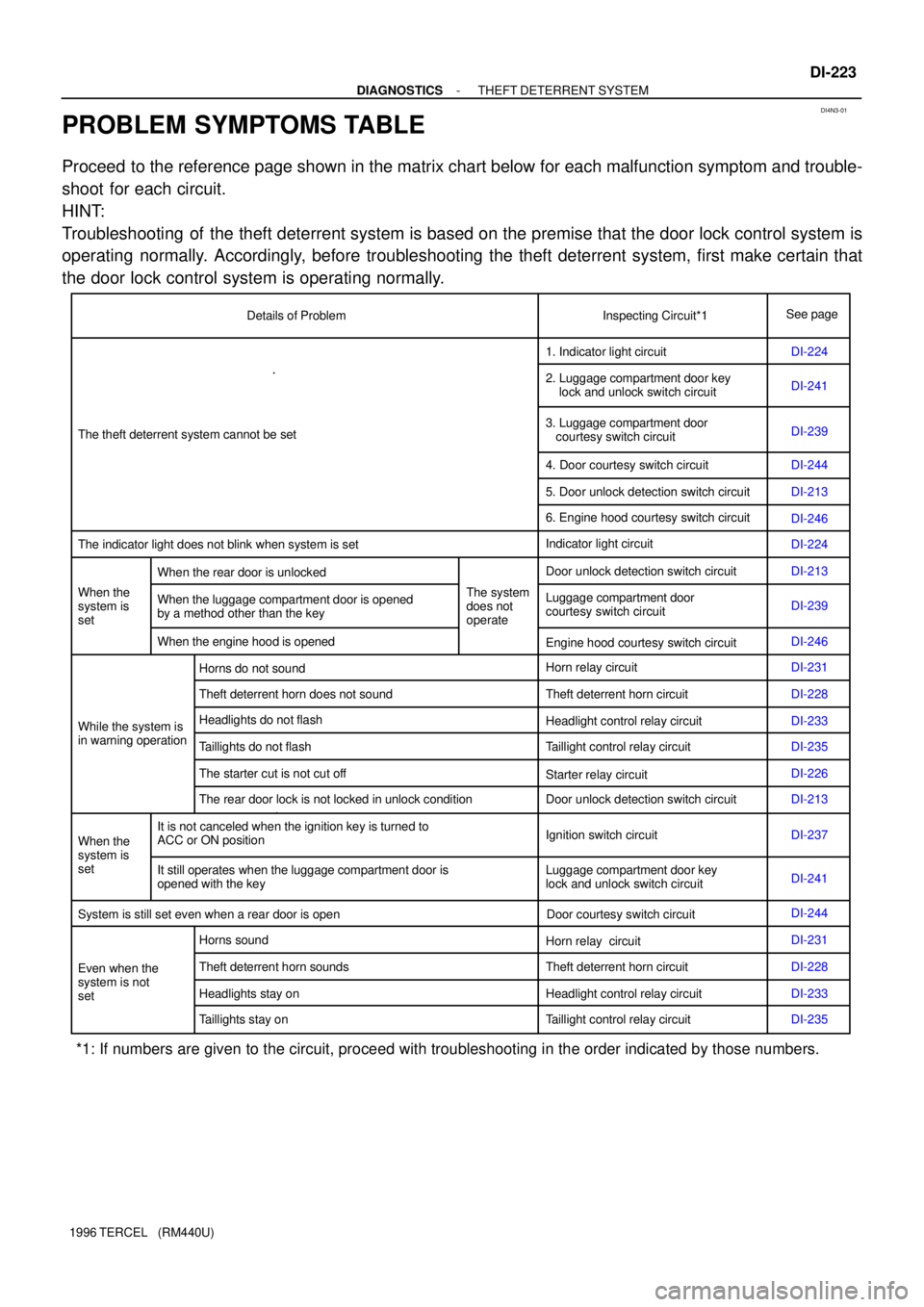
PROBLEM SYMPTOMS TABLE
Proceed to the reference page shown in the matrix chart below for each malfunction symptom and trouble-
shoot for each circuit.
HINT:
Troubleshooting of the theft deterrent system is based on the premise that the door lock control system is
operating normally. Accordingly, before troubleshooting the theft deterrent system, first make certain that
the door lock control system is operating normally.
Page 401 of 1202
N20818
Battery MAIN FL B
EA21Engine Room Relay BlockMAIN AM2 22
Starter Relay
2
2B
EA17
S21
Starter B-R2
IC1B-R25
T4
SRLY
B-R
IC1
12 B-RIgnition Switch
78
IG2
7B
23
EA1
14A AJUNCTION
CONNECTOR
B-W
(A/T) Park/Neutral
Position Switch Clutch Start Switch
1
2
B-W3
IG2B-W
(M/T)Theft Deterrent ECU
C6
I10
P1J1
B-W
B-W
DI-226
- DIAGNOSTICSTHEFT DETERRENT SYSTEM
1996 TERCEL (RM440U)
Starter Relay Circuit
CIRCUIT DESCRIPTION
When the theft deterrent system is activated, contact (a) in the ECU becomes open, creating an open circuit
in terminal SRLY circuit and making the starter inoperative (starter cut).
In this condition, if one of the following operations is done, the contact (a) in the ECU is grounded, thus can-
celing the starter cut:
(1) Unlock the front LH or RH door with key.
(2) Unlock the doors with the wireless door lock control system.
WIRING DIAGRAM
DI4N5-02
Page 403 of 1202
N20819
Theft Deterrent ECU
SH T411
V-W IC2
4
V-W
1
2
W
Engine Room
Relay Block
MAIN FL
Battery 2
1
EA2BB
Theft Deterrent Horn
HAZ-HORN
W
T1 DI-228
- DIAGNOSTICSTHEFT DETERRENT SYSTEM
1996 TERCEL (RM440U)
Theft Deterrent Horn Circuit
CIRCUIT DESCRIPTION
When the theft deterrent system is activated, contact (a) and contact (b) in the ECU close alternately in cycles
of approximately 0.2 sec., causing the theft deterrent horn to blow (See the wiring diagram below).
In this condition, if any of the following operations is done, the contact (a) in the ECU opens, thus stopping
the theft deterrent horn from blowing:
(1) Unlock the front LH or RH door with key.
(2) Turn the ignition switch to ACC or ON position.
(3) Unlock the doors with the wireless door lock control system.
(4) Wait for approximately 60 seconds.
WIRING DIAGRAM
DI4N6-02