Page 23 of 1202

- INTRODUCTIONHOW TO TROUBLESHOOT ECU CONTROLLED
SYSTEMSIN-23
1996 TERCEL (RM440U)
5. PROBLEM SYMPTOMS TABLE
The suspected circuits or parts for each problem symptom are shown in the table below. Use this table to
troubleshoot the problem when a ºNormalº code is displayed in the diagnostic trouble code check but the
problem is still occurring. Numbers in the table indicate the inspection order in which the circuits or parts
should be checked.
HINT:
When the problem is not detected by the diagnostic system even though the problem symptom is present,
it is considered that the problem is occurring outside the detection range of the diagnostic system, or that
the problem is occurring in a system other than the diagnostic system.
Symptom
Suspected AreaSee page
Engine does not crank (Does not start)
No initial combustion (Does not start)
No complete combustion (Does not start)1. Starter and starter relay
1. ECM power source circuit
2. Fuel pump control circuit
3. ECM
1. Starter signal circuit
2. Fuel pump control circuit1. Fuel pump control circuitDI-147
DI-151
IN-29
PROBLEM SYMPTOMS TABLE
1. Compression
2. Fuel pump control circuit 1. A/C signal circuit
2. Fuel pump control circuit 1. A/C signal circuit (Compressor circuit)
2. ECM power source circuit 1. Starter signal circuit
2. Fuel pump control circuit1. Starter signal circuit
2. Fuel pump control circuit
3. Compression
idling) High engine idle speed (Poor idling) Hot engine Cold engine (Difficult to start)Engine cranks normally (Difficult to start)
AC-88 DI-144
DI-151
EM-3 DI-151
� Problem Symptom� Page
Indicates the page where the flow chart for each circuit
is located.
� Circuit Inspection, Inspection Order
Indicates the circuit which needs to be checked for each problem
symptom. Check in the order indicated by the numbers.
� Circuit or Part Name
Indicates the circuit or part which needs to be checked.
ST-2
ST-17
DI-144
DI-151
DI-144
DI-151
Page 73 of 1202
PP19A-01
PP-26
- PREPARATIONSTARTING
73 Author�: Date�:
1996 TERCEL (RM440U)
STARTING
SST (Special Service Tools)
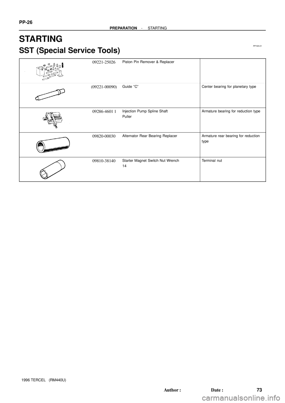
09221-25026Piston Pin Remover & Replacer
(09221-00090)Guide ºCºCenter bearing for planetary type
09286-4601 1Injection Pump Spline Shaft
PullerArmature bearing for reduction type
09820-00030Alternator Rear Bearing ReplacerArmature rear bearing for reduction
type
09810-38140Starter Magnet Switch Nut Wrench
14Terminal nut
Page 149 of 1202
SS0NF-07
- SERVICE SPECIFICATIONSSTARTING
SS-19
149 Author�: Date�:
1996 TERCEL (RM440U)
STARTING
SERVICE DATA
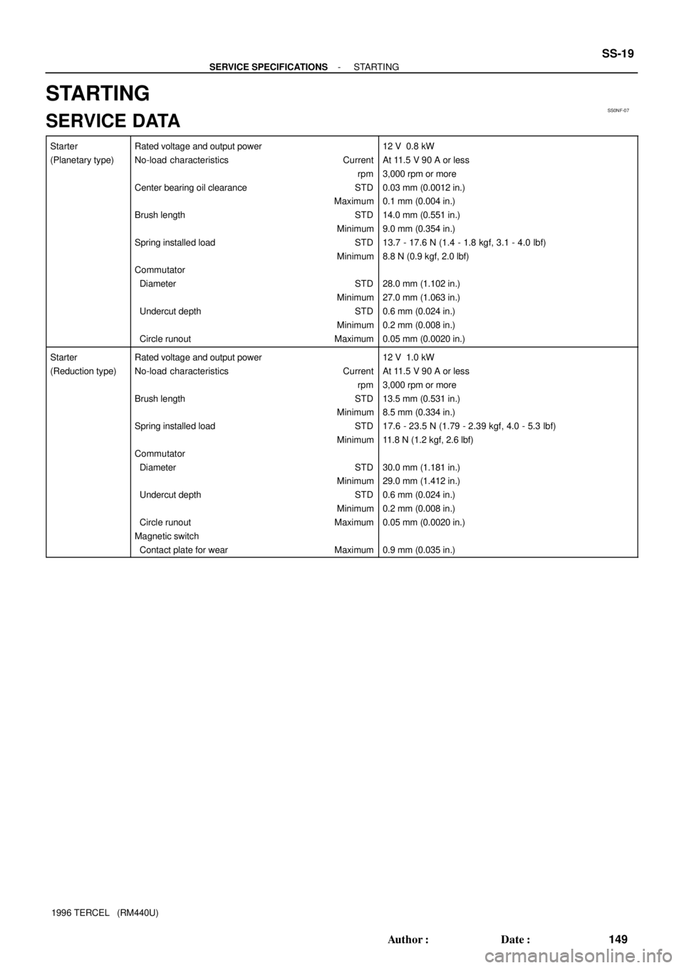
Starter
(Planetary type)Rated voltage and output power
No-load characteristics Current
rpm
Center bearing oil clearance STD
Maximum
Brush length STD
Minimum
Spring installed load STD
Minimum
Commutator
Diameter STD
Minimum
Undercut depth STD
Minimum
Circle runout Maximum12 V 0.8 kW
At 11.5 V 90 A or less
3,000 rpm or more
0.03 mm (0.0012 in.)
0.1 mm (0.004 in.)
14.0 mm (0.551 in.)
9.0 mm (0.354 in.)
13.7 - 17.6 N (1.4 - 1.8 kgf, 3.1 - 4.0 lbf)
8.8 N (0.9 kgf, 2.0 lbf)
28.0 mm (1.102 in.)
27.0 mm (1.063 in.)
0.6 mm (0.024 in.)
0.2 mm (0.008 in.)
0.05 mm (0.0020 in.)
Starter
(Reduction type)Rated voltage and output power
No-load characteristics Current
rpm
Brush length STD
Minimum
Spring installed load STD
Minimum
Commutator
Diameter STD
Minimum
Undercut depth STD
Minimum
Circle runout Maximum
Magnetic switch
Contact plate for wear Maximum12 V 1.0 kW
At 11.5 V 90 A or less
3,000 rpm or more
13.5 mm (0.531 in.)
8.5 mm (0.334 in.)
17.6 - 23.5 N (1.79 - 2.39 kgf, 4.0 - 5.3 lbf)
11.8 N (1.2 kgf, 2.6 lbf)
30.0 mm (1.181 in.)
29.0 mm (1.412 in.)
0.6 mm (0.024 in.)
0.2 mm (0.008 in.)
0.05 mm (0.0020 in.)
0.9 mm (0.035 in.)
Page 150 of 1202
SS0NG-06
SS-20
- SERVICE SPECIFICATIONSSTARTING
1996 TERCEL (RM440U)
TORQUE SPECIFICATION
Part tightenedN´mkgf´cmft´lbf
End cover x Brush holder1.51513 in.´lbf
End cover x Starter housing Planetary type
Reduction type5.9
9.360
9552 in.´lbf
82 in.´lbf
Magnetic switch x Starter housing Planetary type
Reduction type8.3
9.385
9573 in.´lbf
82 in.´lbf
Lead wire of field frame x Magnetic switch Planetary type
Reduction type9.8
5.9100
6087 in.´lbf
52 in.´lbf
Intake manifold x Intake manifold stay17.517513
Cylinder block x Intake manifold stay17.517513
Starter wire x Terminal 30 of starter8.89078 in.´lbf
Starter x Transaxle3737027
Terminal nut x Terminal C of starter1717312
Terminal nut x Terminal 30 of starter1717312
Magnetic switch end cover x Magnetic switch3.63632 in.´lbf
Page 157 of 1202
SS0KQ-04
- SERVICE SPECIFICATIONSMANUAL TRANSAXLE
SS-27
1996 TERCEL (RM440U)
TORQUE SPECIFICATION
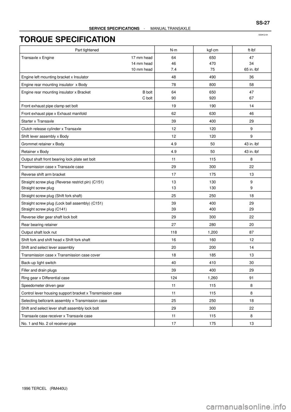
Part tightenedN´mkgf´cmft´lbf
Transaxle x Engine 17 mm head
14 mm head
10 mm head64
46
7.4650
470
7547
34
65 in.´lbf
Engine left mounting bracket x Insulator4849036
Engine rear mounting insulator x Body7880058
Engine rear mounting insulator x Bracket B bolt
C bolt64
90650
92047
67
Front exhaust pipe clamp set bolt1919014
Front exhaust pipe x Exhaust manifold6263046
Starter x Transaxle3940029
Clutch release cylinder x Transaxle121209
Shift lever assembly x Body121209
Grommet retainer x Body4.95043 in.´lbf
Retainer x Body4.95043 in.´lbf
Output shaft front bearing lock plate set bolt1111 58
Transmission case x Transaxle case2930022
Reverse shift arm bracket1717513
Straight screw plug (Reverse restrict pin) (C151)
Straight screw plug13
13130
1309
9
Straight screw plug (Shift fork shaft)2525018
Straight screw plug (Lock ball assembly) (C151)
Straight screw plug (C141)39
39400
40029
29
Reverse idler gear shaft lock bolt2930022
Rear bearing retainer2728020
Output shaft lock nut11 81,20087
Shift fork and shift head x Shift fork shaft1616012
Shift and select lever assembly2020014
Transmission case x Transmission case cover1818513
Back-up light switch4041030
Filler and drain plugs3940029
Ring gear x Differential case1241,26091
Speedometer driven gear1111 58
Control lever housing support bracket x Transmission case1111 58
Selecting bellcrank assembly x Transmission case2525018
Shift and select lever shaft assembly lock bolt2930022
Transaxle case receiver x Transaxle case1111 58
No. 1 and No. 2 oil receiver pipe1717513
Page 159 of 1202
SS0LL-04
- SERVICE SPECIFICATIONSAUTOMATIC TRANSAXLE (A132L)
SS-29
1996 TERCEL (RM440U)
TORQUE SPECIFICATION
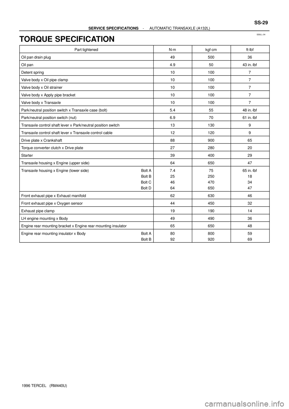
Part tightenedN´mkgf´cmft´lbf
Oil pan drain plug4950036
Oil pan4.95043 in.´lbf
Detent spring101007
Valve body x Oil pipe clamp101007
Valve body x Oil strainer101007
Valve body x Apply pipe bracket101007
Valve body x Transaxle101007
Park/neutral position switch x Transaxle case (bolt)5.45548 in.´lbf
Park/neutral position switch (nut)6.97061 in.´lbf
Transaxle control shaft lever x Park/neutral position switch131309
Transaxle control shaft lever x Transaxle control cable121209
Drive plate x Crankshaft8890065
Torque converter clutch x Drive plate2728020
Starter3940029
Transaxle housing x Engine (upper side)6465047
Transaxle housing x Engine (lower side) Bolt A
Bolt B
Bolt C
Bolt D7.4
25
46
6475
250
470
65065 in.´lbf
18
34
47
Front exhaust pipe x Exhaust manifold6263046
Front exhaust pipe x Oxygen sensor4445032
Exhaust pipe clamp1919014
LH engine mounting x Body4949036
Engine rear mounting bracket x Engine rear mounting insulator6565048
Engine rear mounting insulator x Body Bolt A
Bolt B80
92800
92059
69
Page 161 of 1202
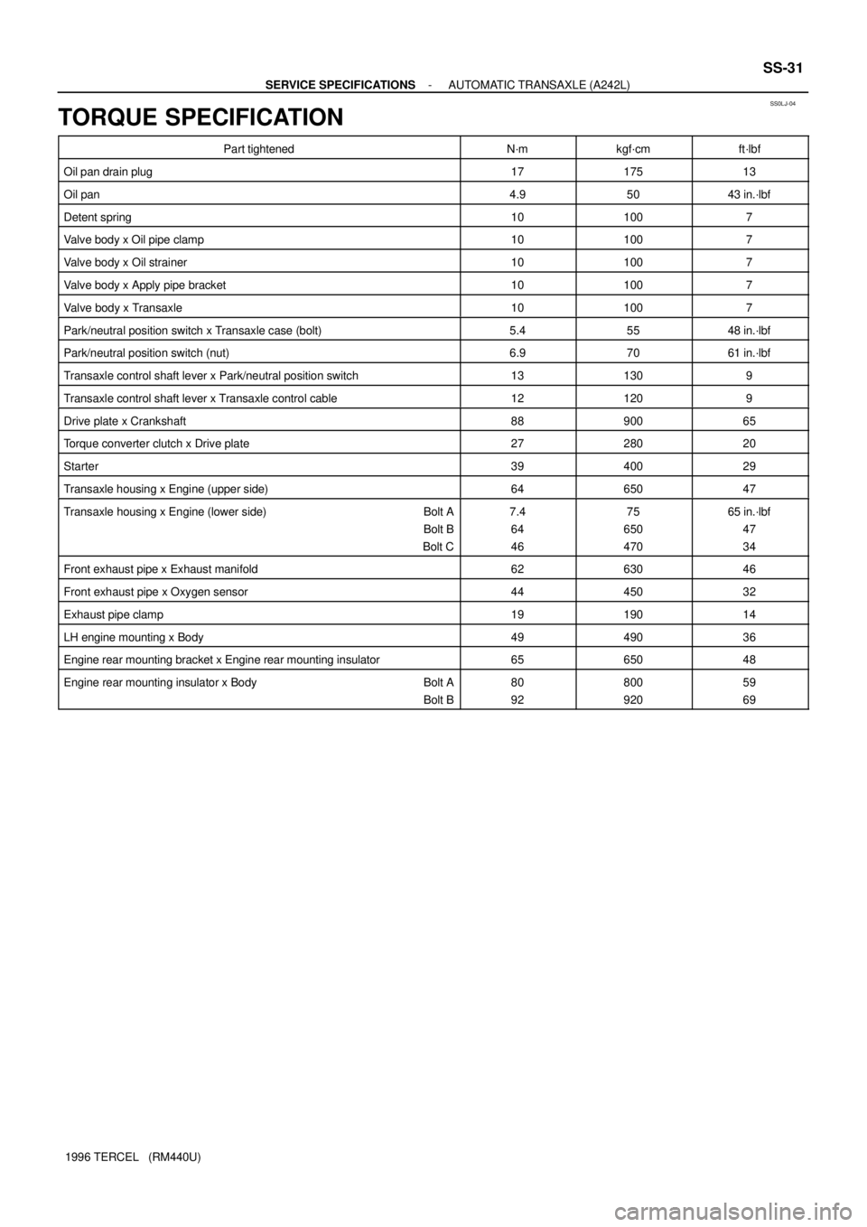
SS0LJ-04
- SERVICE SPECIFICATIONSAUTOMATIC TRANSAXLE (A242L)
SS-31
1996 TERCEL (RM440U)
TORQUE SPECIFICATION
Part tightenedN´mkgf´cmft´lbf
Oil pan drain plug1717513
Oil pan4.95043 in.´lbf
Detent spring101007
Valve body x Oil pipe clamp101007
Valve body x Oil strainer101007
Valve body x Apply pipe bracket101007
Valve body x Transaxle101007
Park/neutral position switch x Transaxle case (bolt)5.45548 in.´lbf
Park/neutral position switch (nut)6.97061 in.´lbf
Transaxle control shaft lever x Park/neutral position switch131309
Transaxle control shaft lever x Transaxle control cable121209
Drive plate x Crankshaft8890065
Torque converter clutch x Drive plate2728020
Starter3940029
Transaxle housing x Engine (upper side)6465047
Transaxle housing x Engine (lower side) Bolt A
Bolt B
Bolt C7.4
64
4675
650
47065 in.´lbf
47
34
Front exhaust pipe x Exhaust manifold6263046
Front exhaust pipe x Oxygen sensor4445032
Exhaust pipe clamp1919014
LH engine mounting x Body4949036
Engine rear mounting bracket x Engine rear mounting insulator6565048
Engine rear mounting insulator x Body Bolt A
Bolt B80
92800
92059
69
Page 186 of 1202

DI-12
- DIAGNOSTICSENGINE
1996 TERCEL (RM440U)
TOYOTA Enhanced Signals:
TOYOTA hand-held tester displayMeasurement ItemNormal Condition*
MISFIRE RPMEngine RPM for first misfire rangeMisfire 0: 0 rpm
MISFIRE LOADEngine load for first misfire rangeMisfire 0: 0 g/r
INJECTORFuel injection time for cylinder No.1Idling: 2.66 - 3.9 ms
IAC DUTY RATIOIntake Air Control Valve Duty Ratio
Opening ratio rotary solenoid type IAC valveIdling: 25.5 - 43 %
STARTER SIGStarter SignalCranking: ON
CTP SIGClosed Throttle Position SignalThrottle Fully Closed: ON
A/C SIGA/C Switch SignalA/C ON: ON
PNP SWPark/Neutral Position Switch SignalP or N position: ON
FC IDLFuel Cut Idle: Fuel cut when throttle valve fully
closed, during decelerationFuel cut operating: ON
FC TAUFuel Cut TAU: Fuel cut during very light loadFuel cut operating: ON
CYL#1, CYL#2, CYL#3, CYL#4Abnormal revolution variation for each cylinder0%
IGNITIONTotal number of ignition for every 1,000 revolu-
tions0 - 2,000 rpm
FUEL PUMPFuel Pump SignalIdling: ON
TOTAL FT B1Total Fuel Trim Bank 1: Average value for fuel
trim system of bank 1Idling: 0.8 - 1.2 V
O2 LR B1, S1
Oxygen Sensor Lean Rich Bank 1, Sensor 1 Re-
sponse time for oxygen sensor output to switch
from lean to rich.
Idling after warmed up: 0 - 1,000 msec.
O2 RL B1, S1
Oxygen Sensor Rich Lean Bank 1, Sensor 1 Re-
sponse time for oxygen sensor output to switch
from rich to lean.
Idling after warmed up: 0 - 1,000 msec.
*: If no conditions are specifically stated for ºldlingº, it means the shift lever is at N or P position, the A/C switch
is OFF and all accessory switches are OFF.