Page 480 of 1202
P20565
M/T EM-58
- ENGINE MECHANICALENGINE UNIT
1996 TERCEL (RM440U)
�Engine coolant temperature sender gauge connec-
tor
�Engine coolant temperature sensor connector
�Camshaft position sensor connector
�EGR VSV
�Fan engine coolant temperature switch connector
�A/T only:
Lock-up solenoid connector
�A/T only:
Park/Neutral position switch connector
�M/T only:
Backup light switch connector
�A/T only:
No.2 vehicle speed sensor connector
�Ground strap
�Throttle position sensor connector
�IAC valve connector
�Injector connectors
�Crankshaft position sensor connector
�Knock sensor connector
�Starter connector and wire
�Generator connector and wire
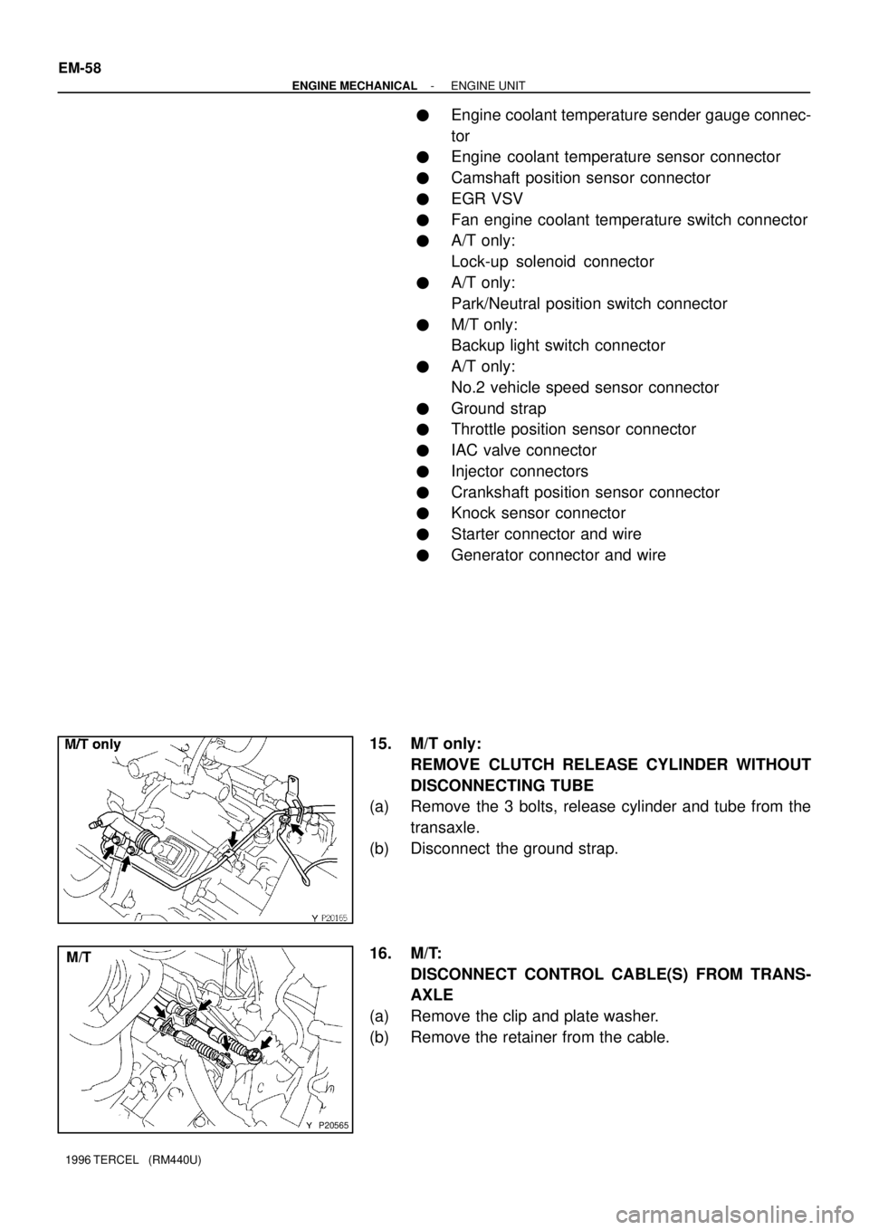
15. M/T only:
REMOVE CLUTCH RELEASE CYLINDER WITHOUT
DISCONNECTING TUBE
(a) Remove the 3 bolts, release cylinder and tube from the
transaxle.
(b) Disconnect the ground strap.
16. M/T:
DISCONNECT CONTROL CABLE(S) FROM TRANS-
AXLE
(a) Remove the clip and plate washer.
(b) Remove the retainer from the cable.
Page 483 of 1202
Z14321
A242L A/T
P20255
Lift
P20167
P20161
P20245
A/T only
- ENGINE MECHANICALENGINE UNIT
EM-61
1996 TERCEL (RM440U)
(j) A242L A/T:
Remove the bolt and disconnect the ground strap.
(k) Remove the 5 bolts and LH engine mounting bracket.
(l) Lift the engine out of the vehicle slowly and carefully.
HINT:
Clear the battery carrier support while lowering the transaxle.
(m) Place the engine with the transaxle onto the stand.
23. w/PS:
REMOVE PS PUMP ADJUSTING STRUT
Remove the 2 bolts and PS pump adjusting strut.
24. w/A/C:
REMOVE A/C COMPRESSOR MOUNTING BRACKET
Remove the 4 bolts and compressor mounting bracket.
25. A/T only:
REMOVE TORQUE CONVERTER CLUTCH MOUNT-
ING BOLTS
(a) Remove the engine rear end plate hole cover.
(b) Turn the crankshaft to gain access to each bolt.
(c) Hold the crankshaft pulley bolt with a wrench.
(d) Remove the 6 bolts.
26. REMOVE STARTER (See page ST-3 and ST-16)
27. SEPARATE ENGINE AND TRANSAXLE
Page 484 of 1202
EM1OI-01
P20245
A/T only
P20161
P20167
P20256
Lower EM-62
- ENGINE MECHANICALENGINE UNIT
1996 TERCEL (RM440U)
INSTALLATION
1. ASSEMBLE ENGINE AND TRANSAXLE
M/T: (See page MX-4)
A132L A/T: (See page AX-26)
A242L A/T: (See page AX-30)
2. INSTALL STARTER
(See page ST-14 and ST-30)
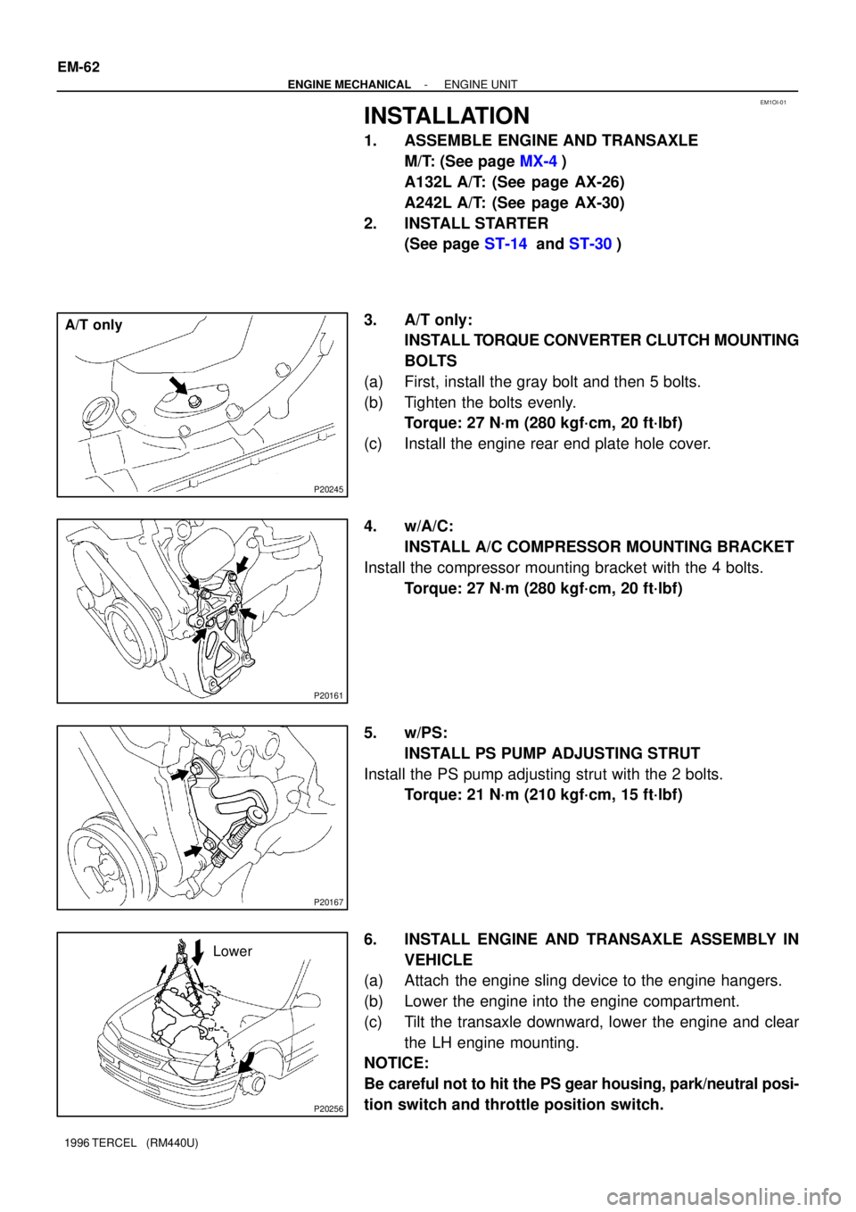
3. A/T only:
INSTALL TORQUE CONVERTER CLUTCH MOUNTING
BOLTS
(a) First, install the gray bolt and then 5 bolts.
(b) Tighten the bolts evenly.
Torque: 27 N´m (280 kgf´cm, 20 ft´lbf)
(c) Install the engine rear end plate hole cover.
4. w/A/C:
INSTALL A/C COMPRESSOR MOUNTING BRACKET
Install the compressor mounting bracket with the 4 bolts.
Torque: 27 N´m (280 kgf´cm, 20 ft´lbf)
5. w/PS:
INSTALL PS PUMP ADJUSTING STRUT
Install the PS pump adjusting strut with the 2 bolts.
Torque: 21 N´m (210 kgf´cm, 15 ft´lbf)
6. INSTALL ENGINE AND TRANSAXLE ASSEMBLY IN
VEHICLE
(a) Attach the engine sling device to the engine hangers.
(b) Lower the engine into the engine compartment.
(c) Tilt the transaxle downward, lower the engine and clear
the LH engine mounting.
NOTICE:
Be careful not to hit the PS gear housing, park/neutral posi-
tion switch and throttle position switch.
Page 488 of 1202
EM-66
- ENGINE MECHANICALENGINE UNIT
1996 TERCEL (RM440U)
15. CONNECT ENGINE WIRE HARNESS
Connect these connectors and wires:
�Main heated oxygen sensor connector
�Oil pressure switch connector
�Engine coolant temperature sender gauge
connector
�Engine coolant temperature sensor connector
�Camshaft position sensor connector
�EGR VSV
�Fan engine coolant temperature switch connector
�A/T only:
Lock-up solenoid connector
�A/T only:
Park/Neutral position switch connector
�M/T only:
Backup light switch connector
�A/T only:
No.2 vehicle speed sensor connector
�Ground strap
�Throttle position sensor connector
�IAC valve connector
�Injector connectors
�Crankshaft position sensor connector
�Knock sensor connector
�Starter connector and wire
�Generator connector and wire
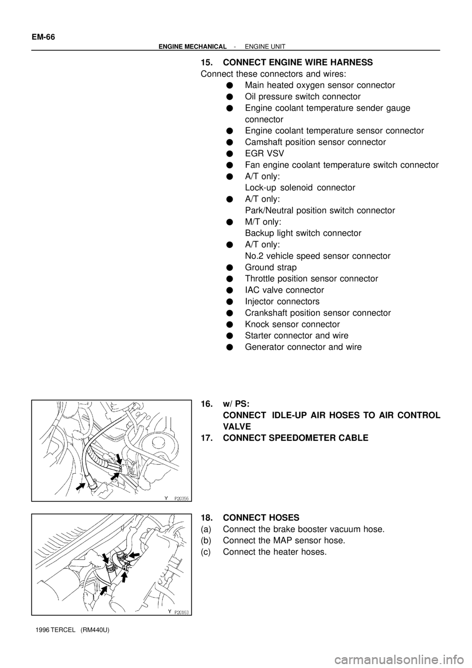
16. w/ PS:
CONNECT IDLE-UP AIR HOSES TO AIR CONTROL
VA LV E
17. CONNECT SPEEDOMETER CABLE
18. CONNECT HOSES
(a) Connect the brake booster vacuum hose.
(b) Connect the MAP sensor hose.
(c) Connect the heater hoses.
Page 647 of 1202
ST07Z-01
- STARTINGSTARTING SYSTEM
ST-1
646 Author�: Date�:
1996 TERCEL (RM440U)
STARTING SYSTEM
ON-VEHICLE INSPECTION
NOTICE:
Before changing the starter, check the following items again:
�Connector connection
�Accessory installation, e.g.: theft deterrent system
Page 648 of 1202
ST0N2-01
B11226
End CoverBrush Holder� Rear BearingArmature� Front Bearing
Field Frame (Field Coil)
Startor Housing
Bearing
Idler Gear
Magnetic Switch Assembly
Return Spring
Steel BallClutch Assembly
� Terminal C Kit Part � Terminal 30 Kit Part
Terminal Nut
Wave Washer
O-Ring
Terminal Insulater Outer
Contact Plate
Insulation
Paper
Terminal Insulater Inner
Terminal Bolt
Lead Clamp
End Cover� GasketPlungerO-Ring
Wave Washer
Terminal Nut
Terminal Insulater Outer
Terminal Bolt
Lead Terminal
Contact Plate
Terminal Insulater Inner
� Non-reusable part ST-2
- STARTINGSTARTER (Reduction Type)
647 Author�: Date�:
1996 TERCEL (RM440U)
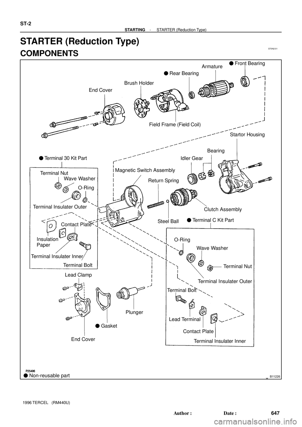
STARTER (Reduction Type)
COMPONENTS
Page 649 of 1202
ST0IW-01
- STARTINGSTARTER (Reduction Type)
ST-3
1996 TERCEL (RM440U)
REMOVAL
REMOVE STARTER (See page ST-16).
Page 650 of 1202
ST0IX-01
P25750
P25751
P25783
Cutout
Protrusion
P25753
ST0941
(2)
(4)(3)
(1) ST-4
- STARTINGSTARTER (Reduction Type)
1996 TERCEL (RM440U)
DISASSEMBLY
1. REMOVE FIELD FRAME AND ARMATURE
(a) Remove the nut, and disconnect the lead wire from the
magnetic switch terminal.
Torque: 5.9 N´m (60 kgf´cm, 52 in.´lbf)
(b) Remove the 2 through bolts.
Torque: 9.3 N´m (95 kgf´cm, 82 in.´lbf)
(c) Pull out the field frame together with the armature.
HINT:
Align the protrusion of the field frame with the grove of the mag-
netic switch.
2. REMOVE STARTER HOUSING, CLUTCH ASSEMBLY
AND GEAR
(a) Remove the 2 screws.
Torque: 9.3 N´m (95 kgf´cm, 82 in.´lbf)
(b) Remove these parts from the magnetic switch:
(1) Starter housing
(2) Idler gear and bearing
(3) Clutch assembly
(4) Return spring
HINT:
Insert the return spring in to the magnetic switch hole.