Page 41 of 1202
- MAINTENANCEINSIDE VEHICLE
MA-3
41 Author�: Date�:
1996 TERCEL (RM440U)
13. ACCELERATOR PEDAL
Check the pedal for smooth operation and uneven pedal effort or catching.
14. CLUTCH PEDAL (See page CL-2)
(a) Check the pedal for smooth operation.
(b) Check that the pedal has the proper freeplay.
15. BRAKE PEDAL (See page BR-6)
(a) Check the pedal for smooth operation.
(b) Check that the pedal has the proper reserve distance and freeplay.
(c) Check the brake booster function.
16. BRAKES
At a safe place, check that the brakes do not pull to one side when applied.
17. PARKING BRAKE (See page BR-8)
(a) Check that the lever has the proper travel.
(b) On a safe incline, check that the vehicle is held securely with only the parking brake applied.
18. AUTOMATIC TRANSMISSION ºPARKº MECHANISM
(a) Check the lock release button of the selector lever for proper and smooth operation.
(b) On a safe incline, check that the vehicle is held securely with the selector lever in the P position and
all brakes released.
Page 47 of 1202

MA02M-05
- MAINTENANCEBODY
MA-9
47 Author�: Date�:
1996 TERCEL (RM440U)
BODY
INSPECTION
1. TIGHTEN BOLTS AND NUTS ON CHASSIS AND BODY
(a) Tighten the front seat-to-body mounting bolts.
Torque: 37 N´m (375 kgf´cm, 27 ft´lbf)
(b) Under Severe Conditions:
In addition to the above maintenance items, check for
loose or missing nuts and bolts on the steering system,
drive train, suspension system, fuel tank mounts, engine
mounts, etc.
2. FINAL INSPECTION
(a) Check the operation of the body parts:
�Hood:
Auxiliary catch operates properly
Hood locks securely when closed
�Front and rear doors:
Door lock operates properly
Doors close properly
�Luggage compartment door:
Door lock operates properly
�Seats:
Seat adjusts easily and locks securely in any posi-
tion
Front seat back locks securely in any position
Folding-down rear seat backs lock securely
(b) Road test:
�Check the engine and chassis for abnormal noises.
�Check that the vehicle does not wander or pull to
one side.
�Check that the brakes work properly and do not
drag.
(b) Be sure to deliver a clean car.
Especially check the steering wheel, shift lever knob, all
switch knobs, door handles and seats.
Page 827 of 1202

SA114-03
R11682
F03986
F03987
SA-10
- SUSPENSION AND AXLEFRONT AXLE HUB
1996 TERCEL (RM440U)
REMOVAL
1. REMOVE FRONT WHEEL
Torque: 103 N´m (1,050 kgf´cm, 76 ft´lbf)
2. w/ ABS
REMOVE BOLT AND ABS SPEED SENSOR
Torque: 7.8 N´m (80 kgf´cm, 69 in.´lbf)
3. REMOVE FRONT BRAKE CALIPER AND DISC
(a) Remove the 2 bolts and brake caliper from the steering
knuckle.
Torque: 88 N´m (900 kgf´cm, 65 in.´lbf)
(b) Support the brake caliper securely.
(c) Remove the disc.
4. CHECK BACKLASH IN BEARING SHAFT DIRECTION
Using a dial indicator, check the backlash near the center of the
axle hub, and check the backlash in the bearing shaft direction.
Maximum: 0.05 mm (0.0020 in.)
If the backlash exceeds the maximum, replace the bearing.
5. CHECK AXLE HUB DEVIATION
Using a dial indicator, check the deviation at the surface of the
axle hub outside the hub bolt.
Maximum: 0.05 mm (0.0020 in.)
If the deviation exceeds the maximum, replace the axle hub.
6. REMOVE DRIVE SHAFT LOCK NUT
(a) Install the brake disc and caliper.
(b) Remove the cotter pin and lock cap.
(c) With applying the brakes, remove the nut.
Torque: 216 N´m (2,200 kgf´cm, 159 ft´lbf)
(d) Remove the brake caliper and disc.
7. LOOSEN 2 NUTS ON LOWER SIDE OF SHOCK AB-
SORBER
Torque: 245 N´m (2,500 kgf´cm, 181 ft´lbf)
HINT:
�Do not remove the 2 bolts.
�Coat the nut's thread with engine oil.
Page 835 of 1202
SA128-02
FA1535
SST
F03986
SA-18
- SUSPENSION AND AXLEFRONT DRIVE SHAFT
1996 TERCEL (RM440U)
REMOVAL
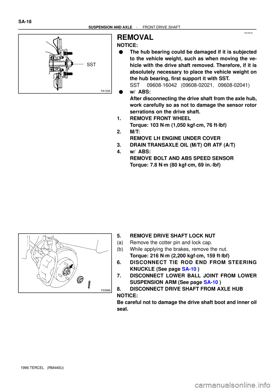
NOTICE:
�The hub bearing could be damaged if it is subjected
to the vehicle weight, such as when moving the ve-
hicle with the drive shaft removed. Therefore, if it is
absolutely necessary to place the vehicle weight on
the hub bearing, first support it with SST.
SST 09608-16042 (09608-02021, 09608-02041)
�w/ ABS:
After disconnecting the drive shaft from the axle hub,
work carefully so as not to damage the sensor rotor
serrations on the drive shaft.
1. REMOVE FRONT WHEEL
Torque: 103 N´m (1,050 kgf´cm, 76 ft´lbf)
2. M/T:
REMOVE LH ENGINE UNDER COVER
3. DRAIN TRANSAXLE OIL (M/T) OR ATF (A/T)
4. w/ ABS:
REMOVE BOLT AND ABS SPEED SENSOR
Torque: 7.8 N´m (80 kgf´cm, 69 in.´lbf)
5. REMOVE DRIVE SHAFT LOCK NUT
(a) Remove the cotter pin and lock cap.
(b) While applying the brakes, remove the nut.
Torque: 216 N´m (2,200 kgf´cm, 159 ft´lbf)
6. DISCONNECT TIE ROD END FROM STEERING
KNUCKLE (See page SA-10)
7. DISCONNECT LOWER BALL JOINT FROM LOWER
SUSPENSION ARM (See page SA-10)
8. DISCONNECT DRIVE SHAFT FROM AXLE HUB
NOTICE:
Be careful not to damage the drive shaft boot and inner oil
seal.