Page 446 of 1202

EG0023
EM-24
- ENGINE MECHANICALCYLINDER HEAD
1996 TERCEL (RM440U)
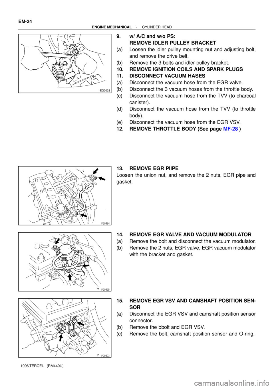
9. w/ A/C and w/o PS:
REMOVE IDLER PULLEY BRACKET
(a) Loosen the idler pulley mounting nut and adjusting bolt,
and remove the drive belt.
(b) Remove the 3 bolts and idler pulley bracket.
10. REMOVE IGNITION COILS AND SPARK PLUGS
11. DISCONNECT VACUUM HASES
(a) Disconnect the vacuum hose from the EGR valve.
(b) Disconnect the 3 vacuum hoses from the throttle body.
(c) Disconnect the vacuum hose from the TVV (to charcoal
canister).
(d) Disconnect the vacuum hose from the TVV (to throttle
body).
(e) Disconnect the vacuum hose from the EGR VSV.
12. REMOVE THROTTLE BODY (See page MF-28)
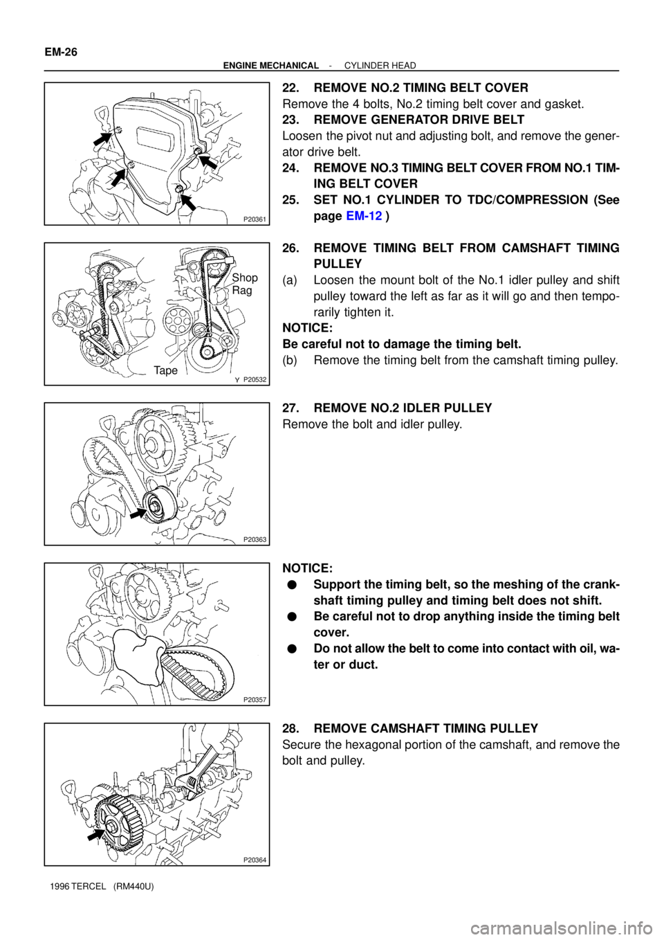
13. REMOVE EGR PIIPE
Loosen the union nut, and remove the 2 nuts, EGR pipe and
gasket.
14. REMOVE EGR VALVE AND VACUUM MODULATOR
(a) Remove the bolt and disconnect the vacuum modulator.
(b) Remove the 2 nuts, EGR valve, EGR vacuum modulator
with the bracket and gasket.
15. REMOVE EGR VSV AND CAMSHAFT POSITION SEN-
SOR
(a) Disconnect the EGR VSV and camshaft position sensor
connector.
(b) Remove the bbolt and EGR VSV.
(c) Remove the bolt, camshaft position sensor and O-ring.
Page 448 of 1202

P20361
P20532
Shop
Rag
Tape
P20363
P20357
P20364
EM-26
- ENGINE MECHANICALCYLINDER HEAD
1996 TERCEL (RM440U)
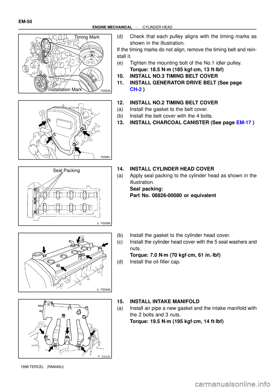
22. REMOVE NO.2 TIMING BELT COVER
Remove the 4 bolts, No.2 timing belt cover and gasket.
23. REMOVE GENERATOR DRIVE BELT
Loosen the pivot nut and adjusting bolt, and remove the gener-
ator drive belt.
24. REMOVE NO.3 TIMING BELT COVER FROM NO.1 TIM-
ING BELT COVER
25. SET NO.1 CYLINDER TO TDC/COMPRESSION (See
page EM-12)
26. REMOVE TIMING BELT FROM CAMSHAFT TIMING
PULLEY
(a) Loosen the mount bolt of the No.1 idler pulley and shift
pulley toward the left as far as it will go and then tempo-
rarily tighten it.
NOTICE:
Be careful not to damage the timing belt.
(b) Remove the timing belt from the camshaft timing pulley.
27. REMOVE NO.2 IDLER PULLEY
Remove the bolt and idler pulley.
NOTICE:
�Support the timing belt, so the meshing of the crank-
shaft timing pulley and timing belt does not shift.
�Be careful not to drop anything inside the timing belt
cover.
�Do not allow the belt to come into contact with oil, wa-
ter or duct.
28. REMOVE CAMSHAFT TIMING PULLEY
Secure the hexagonal portion of the camshaft, and remove the
bolt and pulley.
Page 471 of 1202
P20948
P20953
Timing Mark
Installation
Mark
P20746
P20748
P20749
- ENGINE MECHANICALCYLINDER HEAD
EM-49
1996 TERCEL (RM440U)
8. SET NO.1 CYLINDER TO TDC/COMPRESSION
(a) Turn the crankshaft pulley, and align its groove with timing
mark º0º of the No.1 timing belt cover.
(b) Turn the camshaft, and align the hole of the camshaft tim-
ing pulley on the side with the 5E mark with the timing
mark of the bearing cap.
9. INSTALL TIMING BELT
(a) Starting from the right hand side of the pulley and instal-
ling the belt counterclockwise.
(b) Loosen the No.1 idler pulley mounting bolt until the pulley
is moved slightly by the spring tension.
(c) Turn the crankshaft pulley 2 revolutions from TDC to TDC.
NOTICE:
Always turn the crankshaft clockwise.
Page 472 of 1202

P20538
Timing Mark
Installation Mark
P20361
P20286
Seal Packing
P20406
EM-50
- ENGINE MECHANICALCYLINDER HEAD
1996 TERCEL (RM440U)
(d) Check that each pulley aligns with the timing marks as
shown in the illustration.
If the timing marks do not align, remove the timing belt and rein-
stall it.
(e) Tighten the mounting bolt of the No.1 idler pulley.
Torque: 18.5 N´m (185 kgf´cm, 13 ft´lbf)
10. INSTALL NO.3 TIMING BELT COVER
11. INSTALL GENERATOR DRIVE BELT (See page
CH-2)
12. INSTALL NO.2 TIMING BELT COVER
(a) Install the gasket to the belt cover.
(b) Install the belt cover with the 4 bolts.
13. INSTALL CHARCOAL CANISTER (See page EM-17)
14. INSTALL CYLINDER HEAD COVER
(a) Apply seal packing to the cylinder head as shown in the
illustration.
Seal packing:
Part No. 08826-00080 or equivalent
(b) Install the gasket to the cylinder head cover.
(c) Install the cylinder head cover with the 5 seal washers and
nuts.
Torque: 7.0 N´m (70 kgf´cm, 61 in.´lbf)
(d) Install the oil filler cap.
15. INSTALL INTAKE MANIFOLD
(a) Install air pipe a new gasket and the intake manifold with
the 2 bolts and 3 nuts.
Torque: 19.5 N´m (195 kgf´cm, 14 ft´lbf)
Page 475 of 1202

EG0023
P20290
- ENGINE MECHANICALCYLINDER HEAD
EM-53
1996 TERCEL (RM440U)
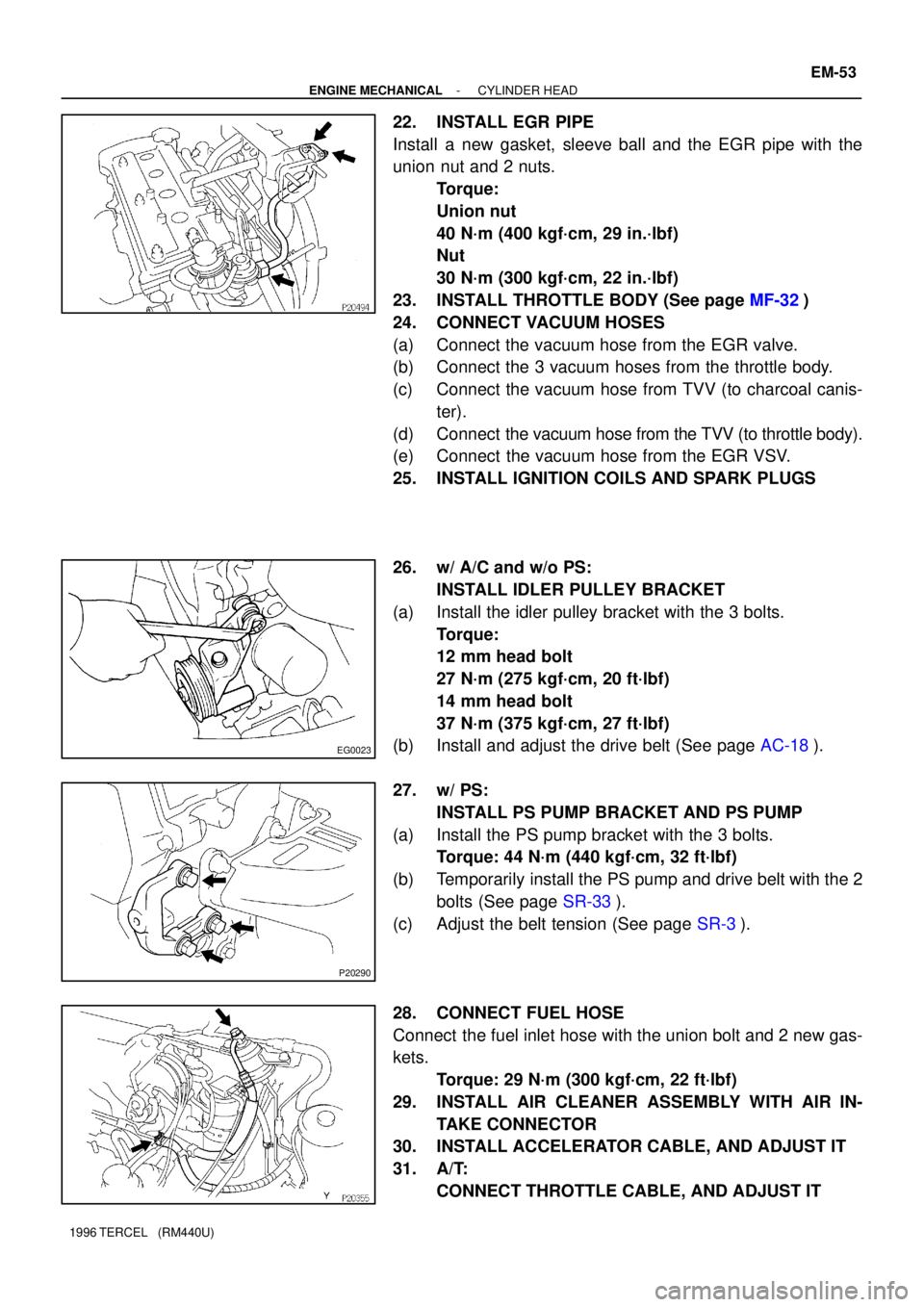
22. INSTALL EGR PIPE
Install a new gasket, sleeve ball and the EGR pipe with the
union nut and 2 nuts.
Torque:
Union nut
40 N´m (400 kgf´cm, 29 in.´lbf)
Nut
30 N´m (300 kgf´cm, 22 in.´lbf)
23. INSTALL THROTTLE BODY (See page MF-32)
24. CONNECT VACUUM HOSES
(a) Connect the vacuum hose from the EGR valve.
(b) Connect the 3 vacuum hoses from the throttle body.
(c) Connect the vacuum hose from TVV (to charcoal canis-
ter).
(d) Connect the vacuum hose from the TVV (to throttle body).
(e) Connect the vacuum hose from the EGR VSV.
25. INSTALL IGNITION COILS AND SPARK PLUGS
26. w/ A/C and w/o PS:
INSTALL IDLER PULLEY BRACKET
(a) Install the idler pulley bracket with the 3 bolts.
Torque:
12 mm head bolt
27 N´m (275 kgf´cm, 20 ft´lbf)
14 mm head bolt
37 N´m (375 kgf´cm, 27 ft´lbf)
(b) Install and adjust the drive belt (See page AC-18).
27. w/ PS:
INSTALL PS PUMP BRACKET AND PS PUMP
(a) Install the PS pump bracket with the 3 bolts.
Torque: 44 N´m (440 kgf´cm, 32 ft´lbf)
(b) Temporarily install the PS pump and drive belt with the 2
bolts (See page SR-33).
(c) Adjust the belt tension (See page SR-3).
28. CONNECT FUEL HOSE
Connect the fuel inlet hose with the union bolt and 2 new gas-
kets.
Torque: 29 N´m (300 kgf´cm, 22 ft´lbf)
29. INSTALL AIR CLEANER ASSEMBLY WITH AIR IN-
TAKE CONNECTOR
30. INSTALL ACCELERATOR CABLE, AND ADJUST IT
31. A/T:
CONNECT THROTTLE CABLE, AND ADJUST IT
Page 481 of 1202
P20572
A132 LA/T
A242 LA/T
P20577
P20292
P20164
- ENGINE MECHANICALENGINE UNIT
EM-59
1996 TERCEL (RM440U)
17. A/T:
DISCONNECT CONTROL CABLE(S) FROM TRANS-
AXLE
(a) Remove the clip and plate washer.
(b) Remove the 2 bolts from the LH engine mounting bracket.
18. w/ PS:
REMOVE PS PUMP WITHOUT DISCONNECTING
HOSES
(a) Loosen the 2 bolts, and remove the PS drive belt.
(b) Remove the 2 bolts, and disconnect the PS pump from
the engine.
HINT:
Put aside the PS pump, and suspend it.
19. w/ A/C:
REMOVE A/C COMPRESSOR
(a) Disconnect the compressor connector.
(b) Remove the 4 compressor mounting bolts.
HINT:
Put aside the compressor, and suspend it.
20. REMOVE FRONT EXHAUST PIPE
(a) Disconnect the heated oxygen sensor.
(b) Remove the 2 bolts, compression springs and disconnect
the exhaust pipe.
(c) Remove the bolts and rear clamp.
(d) Disconnect the 2 rings and remove the front exhaust pipe.
21. REMOVE DRIVE SHAFTS (See page SA-18)
Page 487 of 1202
P20577
P20565
M/T
P21044
A132L A/T
P21045
A242L A/T
S06150
M/T only
- ENGINE MECHANICALENGINE UNIT
EM-65
1996 TERCEL (RM440U)
10. w/ PS:
INSTALL PS PUMP
(a) Install the PS pump and drive belt with the 2 bolts.
(b) Adjust the drive belt tension (See page SR-3).
11. M/T:
CONNECT CONTROL CABLE(S) TO TRANSAXLE
(a) Install the retainer to the cable.
(b) Connect the linkage with the plate washer and clip.
12. A132L A/T:
CONNECT CONTROL CABLE(S) TO TRANSAXLE
(a) Install the support bracket to the LH engine mounting
bracket with the 2 bolts.
(b) Connect the linkage with the plate washer and clip.
13. A242L A/T:
CONNECT CONTROL CABLE(S) TO TRANSAXLE
(a) Install the support bracket to the LH engine mounting
bracket with the 2 bolts.
(b) Connect the linkage with the plate washer and clip.
14. M/T only:
INSTALL CLUTCH RELEASE CYLINDER
Install the release cylinder, tube and ground strap with the 3
bolts.
Torque: 12 N´m (120 kgf´cm, 9 ft´lbf)
Page 492 of 1202
EM0JQ-06
EM9411
EM9412
P20480
SST
P20478
SST
P20477
12 mm
Hexagon
Wrench EM-70
- ENGINE MECHANICALCYLINDER BLOCK
1996 TERCEL (RM440U)
DISASSEMBLY
1. M/T:
REMOVE CLUTCH COVER AND DISC
2. REMOVE FLYWHEEL (M/T) OR DRIVE PLATE (A/T)
3. REMOVE REAR END PLATE
4. INSTALL ENGINE TO ENGINE STAND FOR DIS-
ASSEMBLY
5. REMOVE TIMING BELT AND PULLEYS
6. REMOVE CYLINDER HEAD
7. REMOVE OIL DIPSTICK GUIDE AND GENERATOR
ADJUSTING BAR
8. REMOVE WATER PUMP WITH WATER INLET PIPE
9. REMOVE GENERATOR BRACKET
10. REMOVE KNOCK SENSOR
Using SST, remove the knock sensor.
SST 09816-30010
11. REMOVE RH ENGINE MOUNTING BRACKET
12. REMOVE OIL FILTER
13. REMOVE OIL PRESSURE SWITCH
Using SST, remove the oil pressure switch.
SST 09816-30010
14. REMOVE OIL PUMP AND PRESSURE REGULATOR
VA LV E
15. REMOVE OIL FILTER UNION
Using a 12 mm hexagon wrench, remove the oil filter union.