Page 906 of 1202
Q10145
Attachment
Attachment
IN
OUT
Pressure Feed TubeSST
PS Vane Pump
Z15498
Oil
Reservoir
PS Vane
Pump PS Gear
SST Closed
- STEERINGPOWER STEERING FLUID
SR-7
1996 TERCEL (RM440U)
2. CHECK STEERING FLUID PRESSURE
(a) Disconnect the pressure feed tube from the PS vane
pump. (See page SR-24)
(b) Connect SST, as shown in the illustration below.
SST 09640-10010 (09641-01010, 09641-01030,
09641-01060)
NOTICE:
Check that the valve of the SST is in the open position.
(c) Bleed the power steering system.
(d) Start the engine and run it at idle.
(e) Turn the steering wheel from lock to lock several times to
boost fluid temperature.
Fluid temperature: 80 °C (176 °F)
(f) With the engine idling, close the valve of the SST and ob-
serve the reading on the SST.
Minimum fluid pressure:
6,374 kPa (65 kgf/cm
2, 925 psi)
NOTICE:
�Do not keep the valve closed for more than 10 se-
conds.
�Do not let the fluid temperature become too high.
Page 907 of 1202
Z15499
Oil
Reservoir
PS Vane
Pump PS Gear
SST Open
Z15500
Oil
Reservoir
PS Vane
Pump PS Gear
SST Open Lock Position SR-8
- STEERINGPOWER STEERING FLUID
1996 TERCEL (RM440U)
(g) With the engine idling, open the valve fully.
(h) Measure the fluid pressure at engine speeds of 1,000 rpm
and 3,000 rpm.
Difference fluid pressure:
490 kPa (5 kgf/cm
2, 71 psi) or less
NOTICE:
Do not turn the steering wheel.
(i) With the engine idling and valve fully opened, turn the
steering wheel to full lock position.
Minimum fluid pressure:
6,374 kPa (65 kgf/cm
2, 925 psi)
NOTICE:
�Do not maintain lock position for more than 10 se-
conds.
�Do not let the fluid temperature become too high.
(j) Disconnect the SST.
(k) Connect the pressure feed tube (See page SR-33).
(l) Bleed the power steering system.
Page 913 of 1202

R12213
A
B
Matchmarks
Manual Steering: SR-14
- STEERINGNON-TIL T STEERING COLUMN
1996 TERCEL (RM440U)
4. REMOVE CENTER UPPER INSTRUMENT CLUSTER
FINISH PANEL
(a) Remove the screw.
(b) Remove the 3 clips.
5. REMOVE UPPER AND LOWER COLUMN COVERS
Remove the 6 screws.
6. REMOVE FRONT DOOR SCUFF PLATE AND COWL
SIDE TRIM
Remove the clip and trim.
7. REMOVE LOWER INSTRUMENT COVER AND
INSTRUMENT PANEL LOWER PAD INSERT
(a) Remove the 2 opening covers from the instrument cover.
(b) Remove the 2 screws and disconnect the hood lock re-
lease lever from the instrument cover.
(c) Remove the 4 panel cover set bolts.
(d) Remove the lower pad insert from the instrument cover.
8. REMOVE NO.2 HEATER TO REGISTER DUCT
(a) Disconnect the junction block No.1 with the 3 screws.
(b) Remove the clip.
9. REMOVE COMBINATION SWITCH WITH SPIRAL
CABLE
(a) Disconnect the 3 connectors.
(b) w/ Airbag:
Disconnect the airbag connector.
(c) w/ Airbag:
Remove the 3 screws.
10. REMOVE SPIRAL CABLE (See page BE-14)
NOTICE:
Do not disassemble the cable or apply oil to it.
11. REMOVE COLUMN HOLE COVER
Remove the 4 nuts.
12. DISCONNECT SLIDING YOKE
(a) Place matchmarks on the yoke and steering pinion shaft/
control valve shaft.
(b) Loosen bolt A and remove bolt B.
Page 916 of 1202

SR17T-02
- STEERINGNON-TIL T STEERING COLUMN
SR-17
1996 TERCEL (RM440U)
INSPECTION
NOTICE:
When using a vise do not overtighten it.
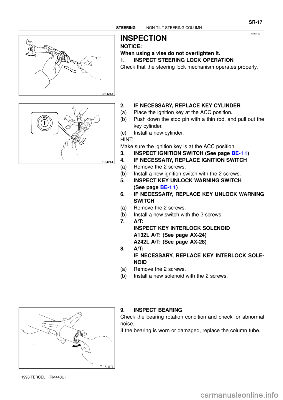
1. INSPECT STEERING LOCK OPERATION
Check that the steering lock mechanism operates properly.
2. IF NECESSARY, REPLACE KEY CYLINDER
(a) Place the ignition key at the ACC position.
(b) Push down the stop pin with a thin rod, and pull out the
key cylinder.
(c) Install a new cylinder.
HINT:
Make sure the ignition key is at the ACC position.
3. INSPECT IGNITION SWITCH (See page BE-1 1)
4. IF NECESSARY, REPLACE IGNITION SWITCH
(a) Remove the 2 screws.
(b) Install a new ignition switch with the 2 screws.
5. INSPECT KEY UNLOCK WARNING SWITCH
(See page BE-1 1)
6. IF NECESSARY, REPLACE KEY UNLOCK WARNING
SWITCH
(a) Remove the 2 screws.
(b) Install a new switch with the 2 screws.
7. A/T:
INSPECT KEY INTERLOCK SOLENOID
A132L A/T: (See page AX-24)
A242L A/T: (See page AX-28)
8. A/T:
IF NECESSARY, REPLACE KEY INTERLOCK SOLE-
NOID
(a) Remove the 2 screws.
(b) Install a new solenoid with the 2 screws.
9. INSPECT BEARING
Check the bearing rotation condition and check for abnormal
noise.
If the bearing is worn or damaged, replace the column tube.
Page 919 of 1202

SR17V-02
R12213
A
B
Matchmarks
Manual Steering: SR-20
- STEERINGNON-TIL T STEERING COLUMN
1996 TERCEL (RM440U)
INSTALLATION
1. INSTALL STEERING COLUMN ASSEMBLY
(a) Torque the 4 column assembly set nuts.
Torque: 25 N´m (260 kgf´cm, 19 ft´lbf)
(b) Connect the connector.
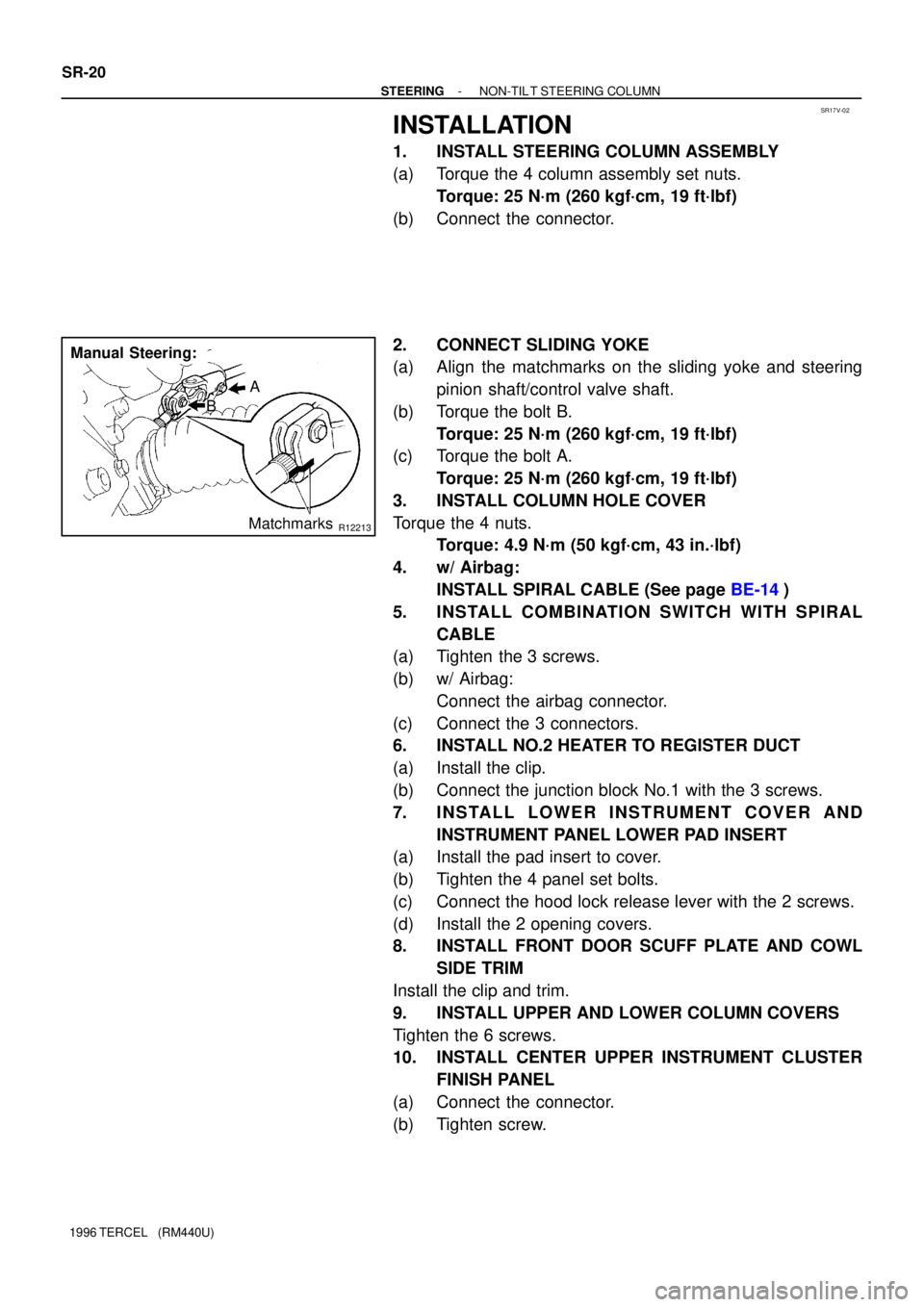
2. CONNECT SLIDING YOKE
(a) Align the matchmarks on the sliding yoke and steering
pinion shaft/control valve shaft.
(b) Torque the bolt B.
Torque: 25 N´m (260 kgf´cm, 19 ft´lbf)
(c) Torque the bolt A.
Torque: 25 N´m (260 kgf´cm, 19 ft´lbf)
3. INSTALL COLUMN HOLE COVER
Torque the 4 nuts.
Torque: 4.9 N´m (50 kgf´cm, 43 in.´lbf)
4. w/ Airbag:
INSTALL SPIRAL CABLE (See page BE-14)
5. INSTALL COMBINATION SWITCH WITH SPIRAL
CABLE
(a) Tighten the 3 screws.
(b) w/ Airbag:
Connect the airbag connector.
(c) Connect the 3 connectors.
6. INSTALL NO.2 HEATER TO REGISTER DUCT
(a) Install the clip.
(b) Connect the junction block No.1 with the 3 screws.
7. INSTALL LOWER INSTRUMENT COVER AND
INSTRUMENT PANEL LOWER PAD INSERT
(a) Install the pad insert to cover.
(b) Tighten the 4 panel set bolts.
(c) Connect the hood lock release lever with the 2 screws.
(d) Install the 2 opening covers.
8. INSTALL FRONT DOOR SCUFF PLATE AND COWL
SIDE TRIM
Install the clip and trim.
9. INSTALL UPPER AND LOWER COLUMN COVERS
Tighten the 6 screws.
10. INSTALL CENTER UPPER INSTRUMENT CLUSTER
FINISH PANEL
(a) Connect the connector.
(b) Tighten screw.
Page 920 of 1202

W01455
Torx ScrewScrew Case
- STEERINGNON-TIL T STEERING COLUMN
SR-21
1996 TERCEL (RM440U)
11. CENTER SPIRAL CABLE
(a) Check that the front wheels are facing straight ahead.
(b) Turn the cable counterclockwise by hand until it becomes
harder to turn the cable.
(c) Then rotate the cable clockwise about 2.5 turns to align
the green marks.
HINT:
The spiral cable turns clockwise about 2.5 turns to either left or
right of the center.
12. INSTALL STEERING WHEEL
(a) Align the matchmarks on the steering wheel and main
shaft assembly.
(b) Torque the steering wheel set nut.
Torque: 34 N´m (350 kgf´cm, 25 ft´lbf)
(c) Connect the connector.
13. w/ Airbag:
INSTALL STEERING WHEEL PAD
NOTICE:
�Make sure the wheel pad is installed with the speci-
fied torque.
�If the wheel pad has been dropped, or there are
cracks, dents or other defects in the case or connec-
tor, replace the wheel pad with a new one.
�When installing the wheel pad, take care that the wir-
ings do not interfere with other parts and that they are
not pinched between other parts.
(a) Connect the airbag connector.
(b) Install the wheel pad after confirming that the circumfer-
ence groove of the torx screws are caught on the screw
case.
(c) Using a torx socket wrench, torque the 2 screws.
Torque: 8.8 N´m (90 kgf´cm, 78 in.´lbf)
14. w/o Airbag:
INSTALL STEERING WHEEL PAD
15. CHECK STEERING WHEEL CENTER POINT
Page 934 of 1202
Z19009
� Non-reusable part
� Precoated part
Molybdenum disulfide lithium base grease Tie Rod End
Lock Nut
Rack End
� Claw Washer
Steering Rack Rack Housing � Bushing Clip
Clamp Rack Boot� Pinion Bearing Adjusting
Screw Lock Nut
� Rack Guide Spring Cap
� Rack Guide Spring
Cap Lock Nut
Rack Guide Rack Guide Spring � Oil Seal
� Pinion Bearing Adjusting Screw
� Bearing
Steering Pinion
� Bearing
Clamp
Rack Boot
Clip
� Claw Washer
Rack End
Lock Nut
Tie Rod End
- STEERINGMANUAL STEERING GEAR
SR-35
955 Author�: Date�:
1996 TERCEL (RM440U)
Page 936 of 1202

SR0KT-01
N00249
SST
N00250
Matchmarks
N00251
R12034
SST
R12035
SST
- STEERINGMANUAL STEERING GEAR
SR-37
1996 TERCEL (RM440U)
DISASSEMBLY
NOTICE:
When using a vise, do not overtighten it.
1. SECURE MANUAL STEERING GEAR IN VISE
Using SST, secure the gear assembly in a vise.
SST 09612-00012
2. REMOVE RH AND LH TIE ROD ENDS AND LOCK
NUTS
Place matchmarks on the tie rod end and rack end.
3. REMOVE RH AND LH CLIPS, RACK BOOTS AND
CLAMPS
Remove the clamp screw from the boot.
NOTICE:
�Be careful not to damage the boot.
�Mark the RH and LH boots.
4. REMOVE RH AND LH RACK ENDS AND CLAW
WASHERS
(a) Using a screwdriver and hammer, unstake the washer.
NOTICE:
Avoid any impact on the steering rack.
(b) Using a spanner, hold the steering rack steadily and using
SST, remove the rack end.
SST 09922-10010
NOTICE:
�Use SST 09922-10010 in the direction shown in the il-
lustration.
�Mark the RH and LH rack ends.
5. REMOVE RACK GUIDE SPRING CAP LOCK NUT
Using SST, remove the nut.
SST 09922-10010
NOTICE:
Use SST 09922-10010 in the direction shown in the illustra-
tion.
6. REMOVE RACK GUIDE SPRING CAP, RACK GUIDE
SPRING AND RACK GUIDE
Using a hexagon wrench (19 mm), remove the cap.