Page 528 of 1202
P20175
New
Gasket
FI1654
Fulcrum Length
SST
30 cm
FI4295
CORRECT
WRONG
WRONG Delivery Pipe O-Ring
Grommet
Injector
FI4296
Delivery
Pipe
O-Ring
Grommet
InjectorCylinder Head
- MFIMFI SYSTEM
MF-3
527 Author�: Date�:
1996 TERCEL (RM440U)
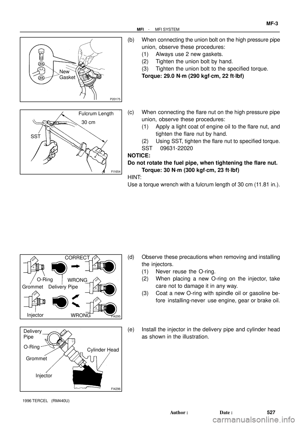
(b) When connecting the union bolt on the high pressure pipe
union, observe these procedures:
(1) Always use 2 new gaskets.
(2) Tighten the union bolt by hand.
(3) Tighten the union bolt to the specified torque.
Torque: 29.0 N´m (290 kgf´cm, 22 ft´lbf)
(c) When connecting the flare nut on the high pressure pipe
union, observe these procedures:
(1) Apply a light coat of engine oil to the flare nut, and
tighten the flare nut by hand.
(2) Using SST, tighten the flare nut to specified torque.
SST 09631-22020
NOTICE:
Do not rotate the fuel pipe, when tightening the flare nut.
Torque: 30 N´m (300 kgf´cm, 23 ft´lbf)
HINT:
Use a torque wrench with a fulcrum length of 30 cm (11.81 in.).
(d) Observe these precautions when removing and installing
the injectors.
(1) Never reuse the O-ring.
(2) When placing a new O-ring on the injector, take
care not to damage it in any way.
(3) Coat a new O-ring with spindle oil or gasoline be-
fore installing-never use engine, gear or brake oil.
(e) Install the injector in the delivery pipe and cylinder head
as shown in the illustration.
Page 529 of 1202
P19552
TOYOTA Hand-Held Tester
DLC3
MF-4
- MFIMFI SYSTEM
528 Author�: Date�:
1996 TERCEL (RM440U)
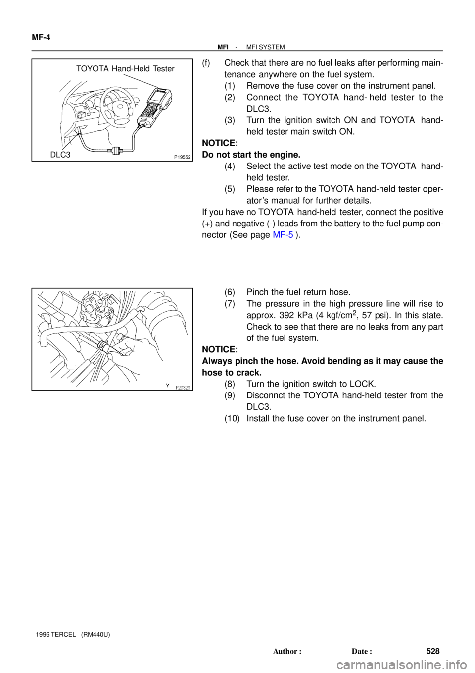
(f) Check that there are no fuel leaks after performing main-
tenance anywhere on the fuel system.
(1) Remove the fuse cover on the instrument panel.
(2) Connect the TOYOTA hand- held tester to the
DLC3.
(3) Turn the ignition switch ON and TOYOTA hand-
held tester main switch ON.
NOTICE:
Do not start the engine.
(4) Select the active test mode on the TOYOTA hand-
held tester.
(5) Please refer to the TOYOTA hand-held tester oper-
ator 's manual for further details.
If you have no TOYOTA hand-held tester, connect the positive
(+) and negative (-) leads from the battery to the fuel pump con-
nector (See page MF-5).
(6) Pinch the fuel return hose.
(7) The pressure in the high pressure line will rise to
approx. 392 kPa (4 kgf/cm
2, 57 psi). In this state.
Check to see that there are no leaks from any part
of the fuel system.
NOTICE:
Always pinch the hose. Avoid bending as it may cause the
hose to crack.
(8) Turn the ignition switch to LOCK.
(9) Disconnct the TOYOTA hand-held tester from the
DLC3.
(10) Install the fuse cover on the instrument panel.
Page 531 of 1202
P20392
SST
MF-6
- MFIFUEL PUMP
530 Author�: Date�:
1996 TERCEL (RM440U)
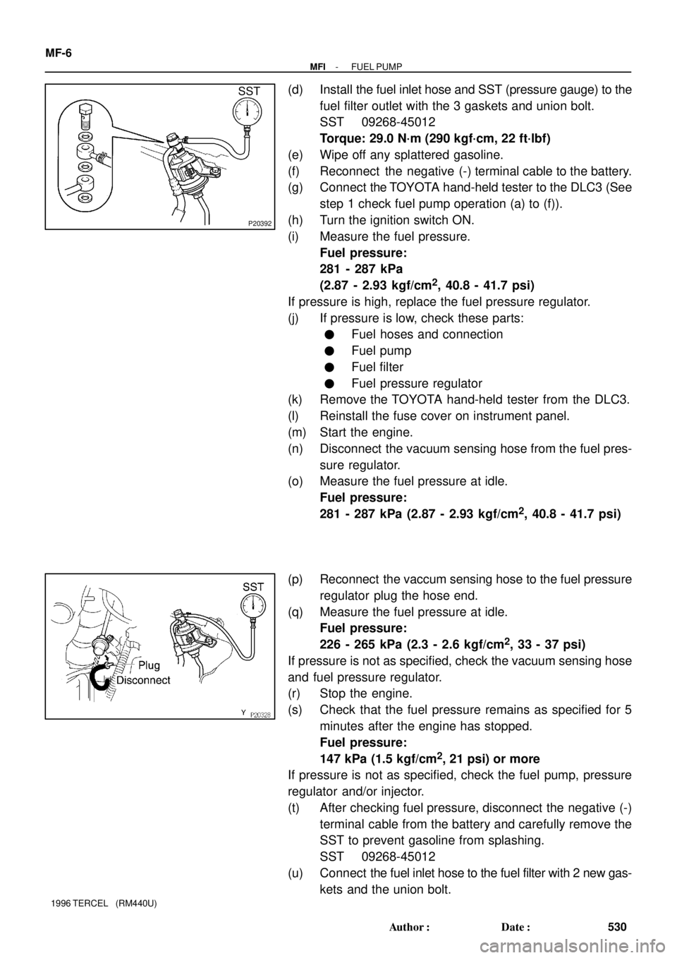
(d) Install the fuel inlet hose and SST (pressure gauge) to the
fuel filter outlet with the 3 gaskets and union bolt.
SST 09268-45012
Torque: 29.0 N´m (290 kgf´cm, 22 ft´lbf)
(e) Wipe off any splattered gasoline.
(f) Reconnect the negative (-) terminal cable to the battery.
(g) Connect the TOYOTA hand-held tester to the DLC3 (See
step 1 check fuel pump operation (a) to (f)).
(h) Turn the ignition switch ON.
(i) Measure the fuel pressure.
Fuel pressure:
281 - 287 kPa
(2.87 - 2.93 kgf/cm
2, 40.8 - 41.7 psi)
If pressure is high, replace the fuel pressure regulator.
(j) If pressure is low, check these parts:
�Fuel hoses and connection
�Fuel pump
�Fuel filter
�Fuel pressure regulator
(k) Remove the TOYOTA hand-held tester from the DLC3.
(l) Reinstall the fuse cover on instrument panel.
(m) Start the engine.
(n) Disconnect the vacuum sensing hose from the fuel pres-
sure regulator.
(o) Measure the fuel pressure at idle.
Fuel pressure:
281 - 287 kPa (2.87 - 2.93 kgf/cm
2, 40.8 - 41.7 psi)
(p) Reconnect the vaccum sensing hose to the fuel pressure
regulator plug the hose end.
(q) Measure the fuel pressure at idle.
Fuel pressure:
226 - 265 kPa (2.3 - 2.6 kgf/cm
2, 33 - 37 psi)
If pressure is not as specified, check the vacuum sensing hose
and fuel pressure regulator.
(r) Stop the engine.
(s) Check that the fuel pressure remains as specified for 5
minutes after the engine has stopped.
Fuel pressure:
147 kPa (1.5 kgf/cm
2, 21 psi) or more
If pressure is not as specified, check the fuel pump, pressure
regulator and/or injector.
(t) After checking fuel pressure, disconnect the negative (-)
terminal cable from the battery and carefully remove the
SST to prevent gasoline from splashing.
SST 09268-45012
(u) Connect the fuel inlet hose to the fuel filter with 2 new gas-
kets and the union bolt.
Page 540 of 1202
SF1PU-02
- MFIFUEL PRESSURE REGULATOR
MF-15
1996 TERCEL (RM440U)
INSTALLATION
1. INSTALL FUEL PRESSURE REGULATOR
(a) Apply a light coat of gasoline to a new O-ring, and install
it to the pressure regulator.
(b) Attach the pressure regulator to the delivery pipe.
(c) Check that the pressure regulator rotates smothly.
NOTICE:
If it does not rotate smothly, the O-ring may be pinched, so
remove the pressure regulator and perform again steps (b)
and (c) above.
(d) Install the pressure regulator with the 3 bolts.
Torque:8.0 N´m (80kgf´cm, 69 in.´lbf)
2. CONNECT FUEL RETURN HOSE TO FUEL PRES-
SURE REGULATOR
3. CONNECT VACUUM SENSING HOSE TO FUEL PRES-
SURE REGULATOR
4. CHECK FOR FUEL LEAKS (See page MF-1)
Page 544 of 1202
SF1PV-02
P20397
Union Bolt
Gasket
SST (Hose)
Fuel Filter
(On Vehicle) SST (Union)
- MFIINJECTOR
MF-19
1996 TERCEL (RM440U)
INSPECTION
1. INSPECT INJECTOR INJECTION
CAUTION:
Keep injector clean of sparks during the test.
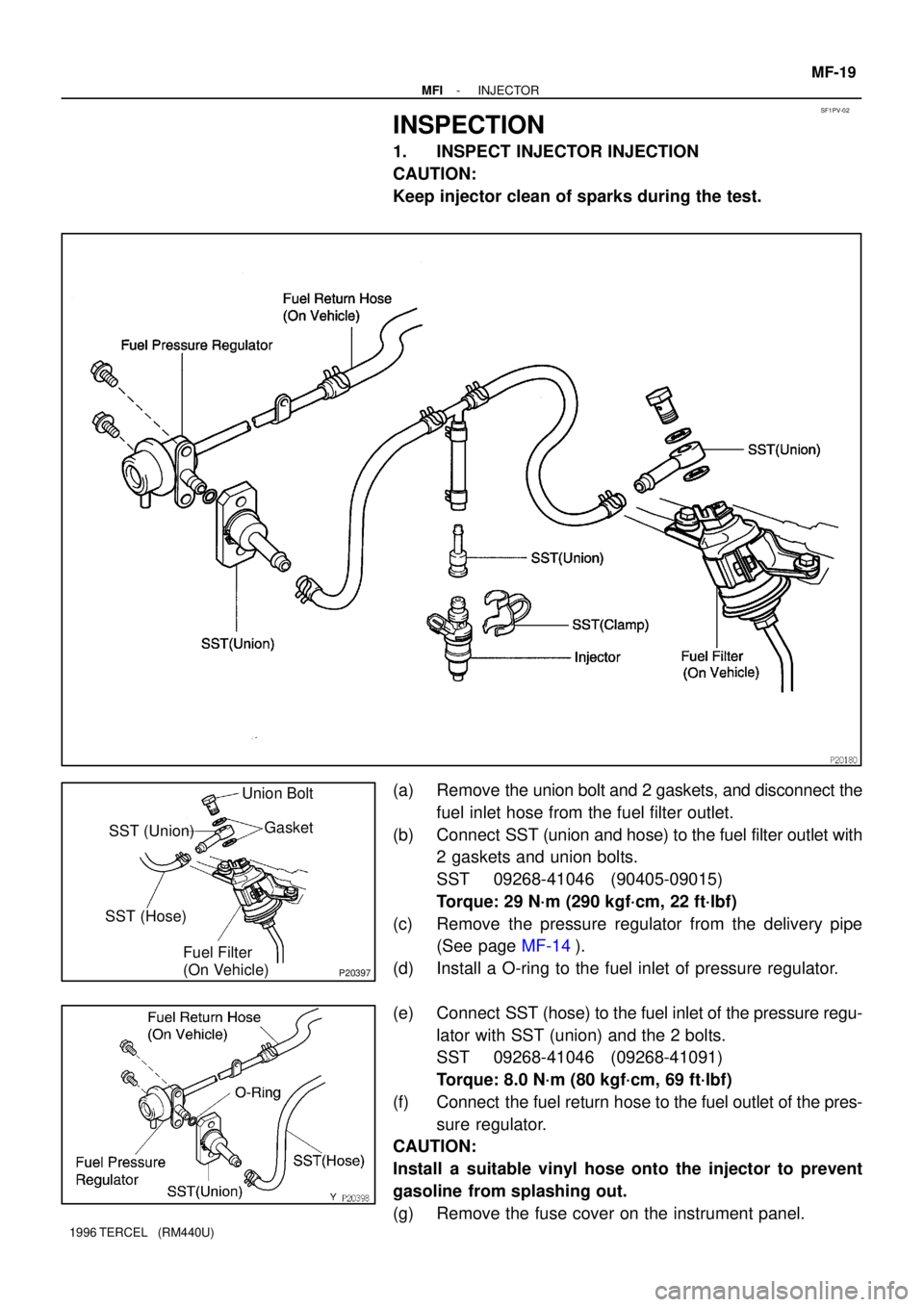
(a) Remove the union bolt and 2 gaskets, and disconnect the
fuel inlet hose from the fuel filter outlet.
(b) Connect SST (union and hose) to the fuel filter outlet with
2 gaskets and union bolts.
SST 09268-41046 (90405-09015)
Torque: 29 N´m (290 kgf´cm, 22 ft´lbf)
(c) Remove the pressure regulator from the delivery pipe
(See page MF-14).
(d) Install a O-ring to the fuel inlet of pressure regulator.
(e) Connect SST (hose) to the fuel inlet of the pressure regu-
lator with SST (union) and the 2 bolts.
SST 09268-41046 (09268-41091)
Torque: 8.0 N´m (80 kgf´cm, 69 ft´lbf)
(f) Connect the fuel return hose to the fuel outlet of the pres-
sure regulator.
CAUTION:
Install a suitable vinyl hose onto the injector to prevent
gasoline from splashing out.
(g) Remove the fuse cover on the instrument panel.
Page 545 of 1202
Z14695
SST (Hose)
SST (Union)
O-Ring
SST
(Clamp)
Vinyl Tube
P19552
TOYOTA Hand-Held Tester
DLC3
FI3211
SST
(Wire)
Connect
FI1676
MF-20
- MFIINJECTOR
1996 TERCEL (RM440U)
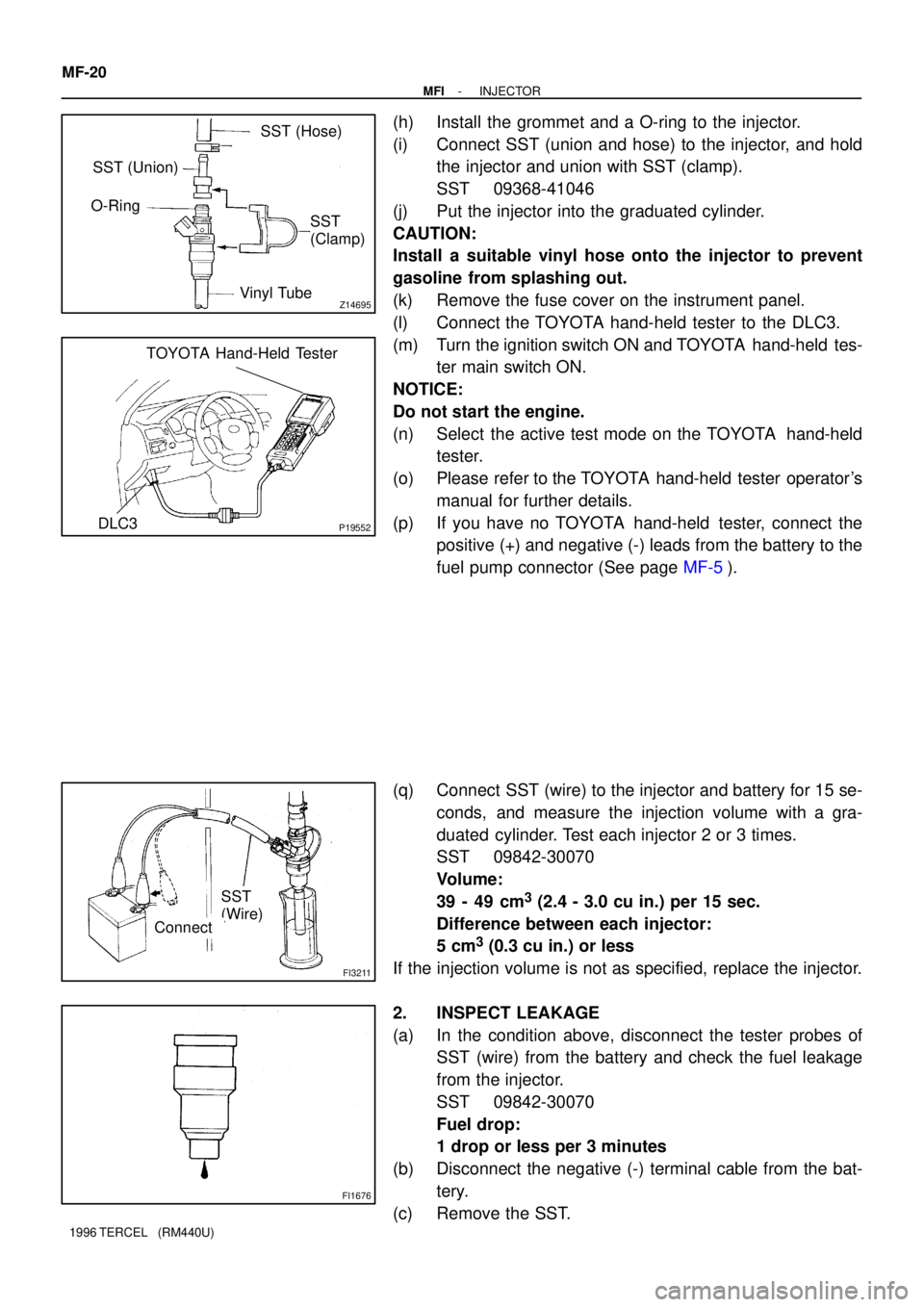
(h) Install the grommet and a O-ring to the injector.
(i) Connect SST (union and hose) to the injector, and hold
the injector and union with SST (clamp).
SST 09368-41046
(j) Put the injector into the graduated cylinder.
CAUTION:
Install a suitable vinyl hose onto the injector to prevent
gasoline from splashing out.
(k) Remove the fuse cover on the instrument panel.
(l) Connect the TOYOTA hand-held tester to the DLC3.
(m) Turn the ignition switch ON and TOYOTA hand-held tes-
ter main switch ON.
NOTICE:
Do not start the engine.
(n) Select the active test mode on the TOYOTA hand-held
tester.
(o) Please refer to the TOYOTA hand-held tester operator's
manual for further details.
(p) If you have no TOYOTA hand-held tester, connect the
positive (+) and negative (-) leads from the battery to the
fuel pump connector (See page MF-5).
(q) Connect SST (wire) to the injector and battery for 15 se-
conds, and measure the injection volume with a gra-
duated cylinder. Test each injector 2 or 3 times.
SST 09842-30070
Volume:
39 - 49 cm
3 (2.4 - 3.0 cu in.) per 15 sec.
Difference between each injector:
5 cm
3 (0.3 cu in.) or less
If the injection volume is not as specified, replace the injector.
2. INSPECT LEAKAGE
(a) In the condition above, disconnect the tester probes of
SST (wire) from the battery and check the fuel leakage
from the injector.
SST 09842-30070
Fuel drop:
1 drop or less per 3 minutes
(b) Disconnect the negative (-) terminal cable from the bat-
tery.
(c) Remove the SST.
Page 547 of 1202
SF0X4-05
FI3271
New
O-Ring
New Grommet
P00159
CORRECT
WRONG
InjectorDelivery Pipe GrommetO-Ring
WRONG
P20295
Spacer
Insulator
Connector MF-22
- MFIINJECTOR
1996 TERCEL (RM440U)
INSTALLATION
1. INSTALL INJECTORS AND DELIVERY PIPE
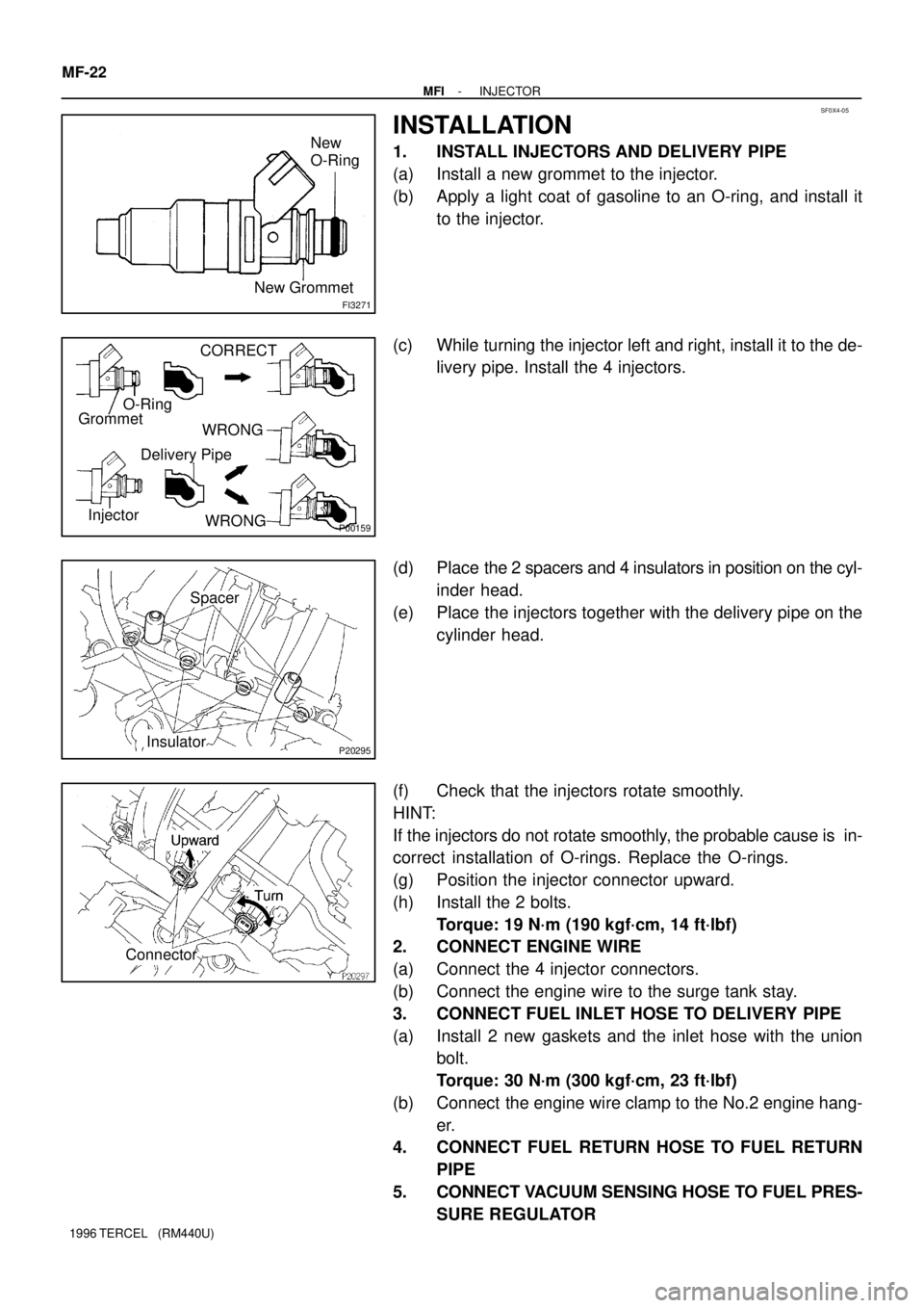
(a) Install a new grommet to the injector.
(b) Apply a light coat of gasoline to an O-ring, and install it
to the injector.
(c) While turning the injector left and right, install it to the de-
livery pipe. Install the 4 injectors.
(d) Place the 2 spacers and 4 insulators in position on the cyl-
inder head.
(e) Place the injectors together with the delivery pipe on the
cylinder head.
(f) Check that the injectors rotate smoothly.
HINT:
If the injectors do not rotate smoothly, the probable cause is in-
correct installation of O-rings. Replace the O-rings.
(g) Position the injector connector upward.
(h) Install the 2 bolts.
Torque: 19 N´m (190 kgf´cm, 14 ft´lbf)
2. CONNECT ENGINE WIRE
(a) Connect the 4 injector connectors.
(b) Connect the engine wire to the surge tank stay.
3. CONNECT FUEL INLET HOSE TO DELIVERY PIPE
(a) Install 2 new gaskets and the inlet hose with the union
bolt.
Torque: 30 N´m (300 kgf´cm, 23 ft´lbf)
(b) Connect the engine wire clamp to the No.2 engine hang-
er.
4. CONNECT FUEL RETURN HOSE TO FUEL RETURN
PIPE
5. CONNECT VACUUM SENSING HOSE TO FUEL PRES-
SURE REGULATOR
Page 549 of 1202
SF0X5-04
MF-24
- MFIFUEL TANK AND LINE
548 Author�: Date�:
1996 TERCEL (RM440U)
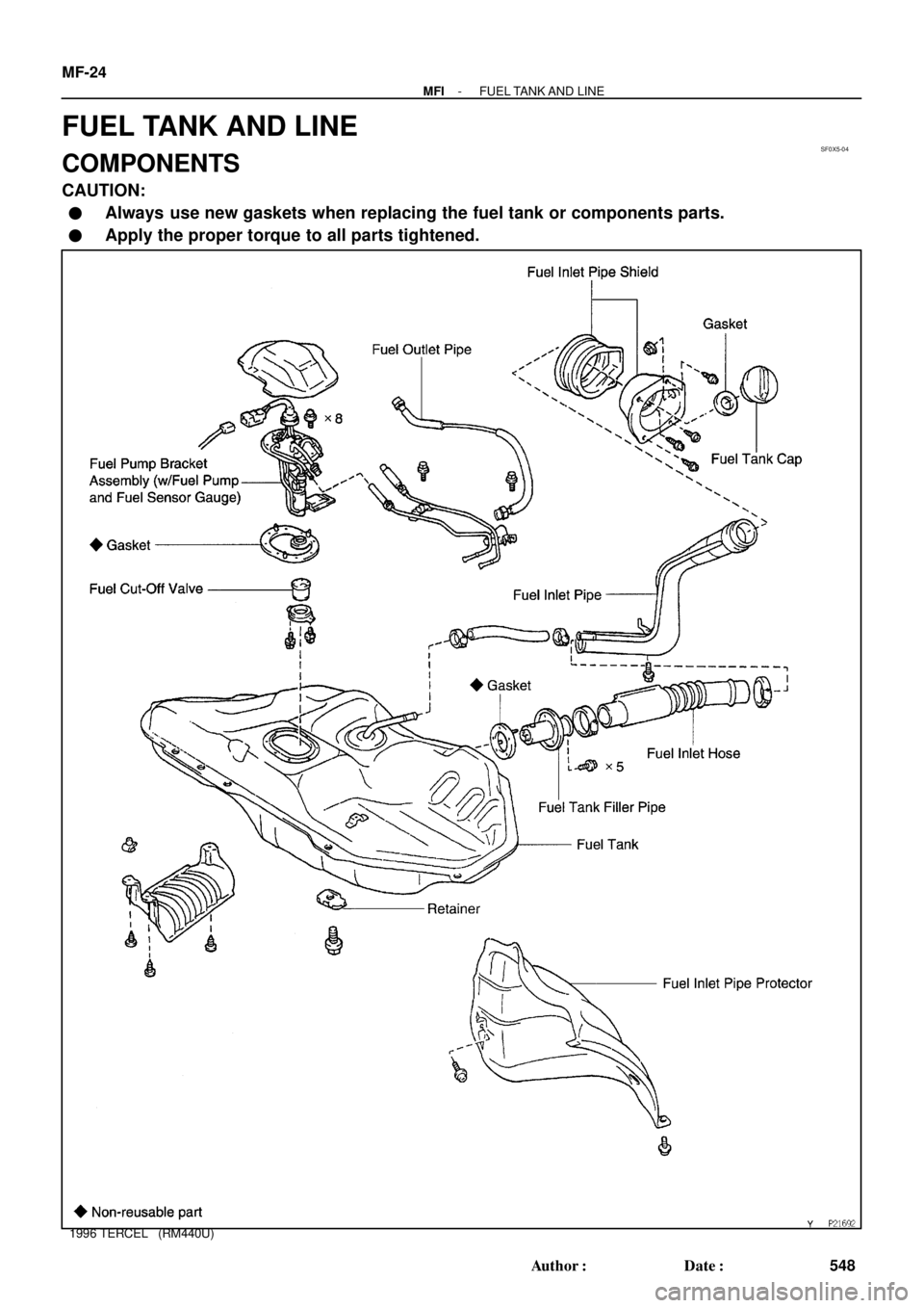
FUEL TANK AND LINE
COMPONENTS
CAUTION:
�Always use new gaskets when replacing the fuel tank or components parts.
�Apply the proper torque to all parts tightened.