Page 913 of 1202

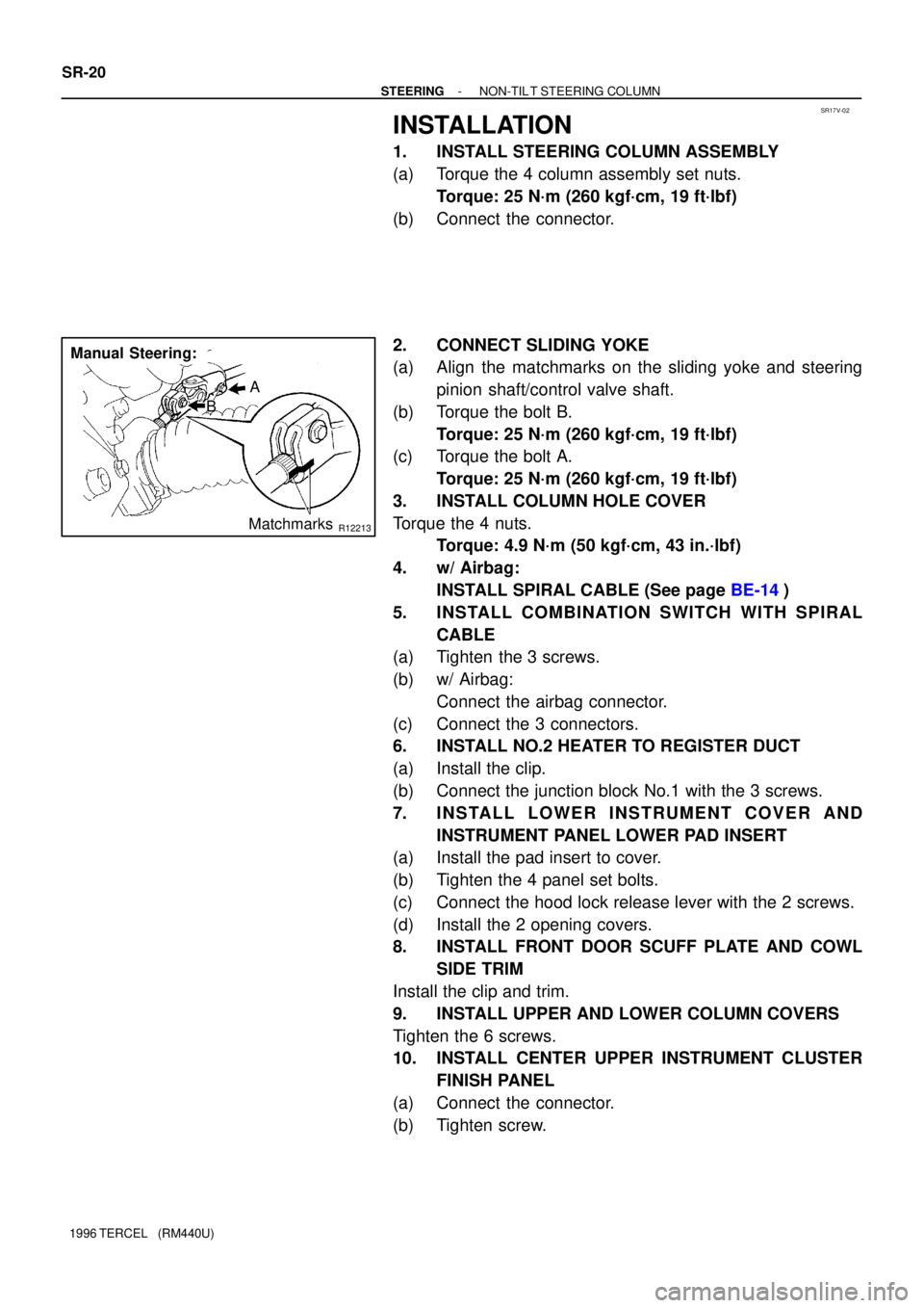
R12213
A
B
Matchmarks
Manual Steering: SR-14
- STEERINGNON-TIL T STEERING COLUMN
1996 TERCEL (RM440U)
4. REMOVE CENTER UPPER INSTRUMENT CLUSTER
FINISH PANEL
(a) Remove the screw.
(b) Remove the 3 clips.
5. REMOVE UPPER AND LOWER COLUMN COVERS
Remove the 6 screws.
6. REMOVE FRONT DOOR SCUFF PLATE AND COWL
SIDE TRIM
Remove the clip and trim.
7. REMOVE LOWER INSTRUMENT COVER AND
INSTRUMENT PANEL LOWER PAD INSERT
(a) Remove the 2 opening covers from the instrument cover.
(b) Remove the 2 screws and disconnect the hood lock re-
lease lever from the instrument cover.
(c) Remove the 4 panel cover set bolts.
(d) Remove the lower pad insert from the instrument cover.
8. REMOVE NO.2 HEATER TO REGISTER DUCT
(a) Disconnect the junction block No.1 with the 3 screws.
(b) Remove the clip.
9. REMOVE COMBINATION SWITCH WITH SPIRAL
CABLE
(a) Disconnect the 3 connectors.
(b) w/ Airbag:
Disconnect the airbag connector.
(c) w/ Airbag:
Remove the 3 screws.
10. REMOVE SPIRAL CABLE (See page BE-14)
NOTICE:
Do not disassemble the cable or apply oil to it.
11. REMOVE COLUMN HOLE COVER
Remove the 4 nuts.
12. DISCONNECT SLIDING YOKE
(a) Place matchmarks on the yoke and steering pinion shaft/
control valve shaft.
(b) Loosen bolt A and remove bolt B.
Page 919 of 1202

SR17V-02
R12213
A
B
Matchmarks
Manual Steering: SR-20
- STEERINGNON-TIL T STEERING COLUMN
1996 TERCEL (RM440U)
INSTALLATION
1. INSTALL STEERING COLUMN ASSEMBLY
(a) Torque the 4 column assembly set nuts.
Torque: 25 N´m (260 kgf´cm, 19 ft´lbf)
(b) Connect the connector.
2. CONNECT SLIDING YOKE
(a) Align the matchmarks on the sliding yoke and steering
pinion shaft/control valve shaft.
(b) Torque the bolt B.
Torque: 25 N´m (260 kgf´cm, 19 ft´lbf)
(c) Torque the bolt A.
Torque: 25 N´m (260 kgf´cm, 19 ft´lbf)
3. INSTALL COLUMN HOLE COVER
Torque the 4 nuts.
Torque: 4.9 N´m (50 kgf´cm, 43 in.´lbf)
4. w/ Airbag:
INSTALL SPIRAL CABLE (See page BE-14)
5. INSTALL COMBINATION SWITCH WITH SPIRAL
CABLE
(a) Tighten the 3 screws.
(b) w/ Airbag:
Connect the airbag connector.
(c) Connect the 3 connectors.
6. INSTALL NO.2 HEATER TO REGISTER DUCT
(a) Install the clip.
(b) Connect the junction block No.1 with the 3 screws.
7. INSTALL LOWER INSTRUMENT COVER AND
INSTRUMENT PANEL LOWER PAD INSERT
(a) Install the pad insert to cover.
(b) Tighten the 4 panel set bolts.
(c) Connect the hood lock release lever with the 2 screws.
(d) Install the 2 opening covers.
8. INSTALL FRONT DOOR SCUFF PLATE AND COWL
SIDE TRIM
Install the clip and trim.
9. INSTALL UPPER AND LOWER COLUMN COVERS
Tighten the 6 screws.
10. INSTALL CENTER UPPER INSTRUMENT CLUSTER
FINISH PANEL
(a) Connect the connector.
(b) Tighten screw.
Page 1116 of 1202
BO1IC-04
N15778
No.2 Heater to
Register Duct
Center Heater to
Register Duct
Instrument Panel Reinforcement
AG
AA
G
G
G
G
G
G
A
A Instrument Panel
Brace No.1
Instrument Panel
Brace No.2
Clock Hole Cover
C
CInstrument Panel
Heater
Control
B
B
B
B
DDD
Lower Center Finish Panel
Center Upper
Cluster Finish Panel
Combination
Mater
Steering Column Cover
Front Pillar Garnish
Combination Switch
Cowl Side
Trim
Front Door
Scuff Plate
Instrument Panel
Lower Pad
Lower Center Finish Panel
Steering Wheel
Center Cluster
Finish Panel
Shifting Hole
Bezel
F
F
Ash Receptacle BoxD
D
D
D
Console Box
Lower Instrument Cover
BB
BBHeater Control Panel
Knob
- BODYINSTRUMENT PANEL
BO-45
1139 Author�: Date�:
1996 TERCEL (RM440U)
INSTRUMENT PANEL
COMPONENTS
Page 1119 of 1202

BO347-01
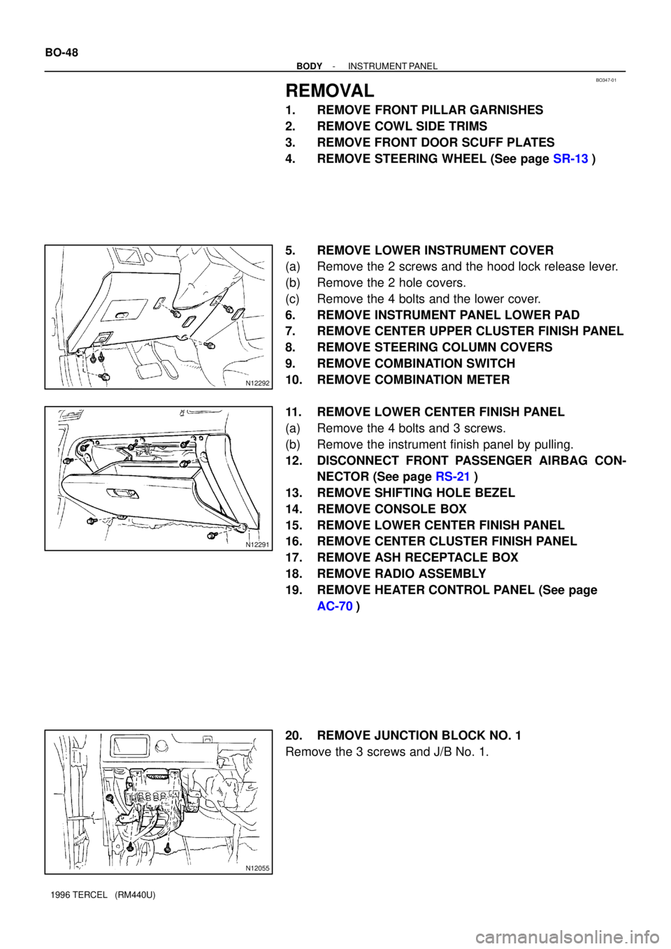
N12292
N12291
N12055
BO-48
- BODYINSTRUMENT PANEL
1996 TERCEL (RM440U)
REMOVAL
1. REMOVE FRONT PILLAR GARNISHES
2. REMOVE COWL SIDE TRIMS
3. REMOVE FRONT DOOR SCUFF PLATES
4. REMOVE STEERING WHEEL (See page SR-13)
5. REMOVE LOWER INSTRUMENT COVER
(a) Remove the 2 screws and the hood lock release lever.
(b) Remove the 2 hole covers.
(c) Remove the 4 bolts and the lower cover.
6. REMOVE INSTRUMENT PANEL LOWER PAD
7. REMOVE CENTER UPPER CLUSTER FINISH PANEL
8. REMOVE STEERING COLUMN COVERS
9. REMOVE COMBINATION SWITCH
10. REMOVE COMBINATION METER
11. REMOVE LOWER CENTER FINISH PANEL
(a) Remove the 4 bolts and 3 screws.
(b) Remove the instrument finish panel by pulling.
12. DISCONNECT FRONT PASSENGER AIRBAG CON-
NECTOR (See page RS-21)
13. REMOVE SHIFTING HOLE BEZEL
14. REMOVE CONSOLE BOX
15. REMOVE LOWER CENTER FINISH PANEL
16. REMOVE CENTER CLUSTER FINISH PANEL
17. REMOVE ASH RECEPTACLE BOX
18. REMOVE RADIO ASSEMBLY
19. REMOVE HEATER CONTROL PANEL (See page
AC-70)
20. REMOVE JUNCTION BLOCK NO. 1
Remove the 3 screws and J/B No. 1.
Page 1199 of 1202
AC3IW-01
AC-70
- AIR CONDITIONINGHEATER CONTROL ASSEMBLY
1996 TERCEL (RM440U)
REMOVAL
1. REMOVE GLOVE COMPARTMENT PARTS
(See page BO-45).
2. REMOVE INSTRUMENT LOWER FINISH PANEL
(See page BO-45).
3. REMOVE CENTER CLUSTER FINISH PANEL
(See page BO-45).
4. DISCONNECT A/C CONTROL CABLES
5. REMOVE A/C CONTROL ASSEMBLY
(a) Remove the heater control knobs.
(b) Remove the A/C switch.
(c) Remove the heater control panel.
(d) Remove the 4 screws and A/C control assembly.