Page 824 of 1202
SA0028
A: Inside
B: Outside AB
Front BA
- SUSPENSION AND AXLEFRONT WHEEL ALIGNMENT
SA-7
823 Author�: Date�:
1996 TERCEL (RM440U)
7. INSPECT WHEEL ANGLE
Turn the steering wheel fully, and measure the turning angle.
Inside wheel35°55' ± 2°
Reference: Outside wheel32°10'
If the wheel angles differ from the standard specifications, in-
spect the toe-in.
Page 825 of 1202
SA112-04
SA3213
AB
C D
Front
SA-8
- SUSPENSION AND AXLEREAR WHEEL ALIGNMENT
824 Author�: Date�:
1996 TERCEL (RM440U)
REAR WHEEL ALIGNMENT
INSPECTION
1. MEASURE VEHICLE HEIGHT (See page SA-4)
NOTICE:
Before inspecting the weel alignment, adjust the vehicle
height to the specitication.
2. INSPECT CAMBER
Camber
Left-right error-0°30' ± 45'
45' (0.75°) or less
HINT:
Camber is not adjustable, if the measurement is not within the
specification, inspect and replace the suspension parts as nec-
essary.
3. INSPECT TOE-IN
Toe-in
(total)A + B: 0.3° ± 0.3°
C - D: 3 ± 3 mm (0.12 ± 0.12 in.)
HINT:
Toe-in is not adjustable, if the measurement is not within the
specification, inspect and replace the suspension parts as nec-
essary.
Page 827 of 1202

SA114-03
R11682
F03986
F03987
SA-10
- SUSPENSION AND AXLEFRONT AXLE HUB
1996 TERCEL (RM440U)
REMOVAL
1. REMOVE FRONT WHEEL
Torque: 103 N´m (1,050 kgf´cm, 76 ft´lbf)
2. w/ ABS
REMOVE BOLT AND ABS SPEED SENSOR
Torque: 7.8 N´m (80 kgf´cm, 69 in.´lbf)
3. REMOVE FRONT BRAKE CALIPER AND DISC
(a) Remove the 2 bolts and brake caliper from the steering
knuckle.
Torque: 88 N´m (900 kgf´cm, 65 in.´lbf)
(b) Support the brake caliper securely.
(c) Remove the disc.
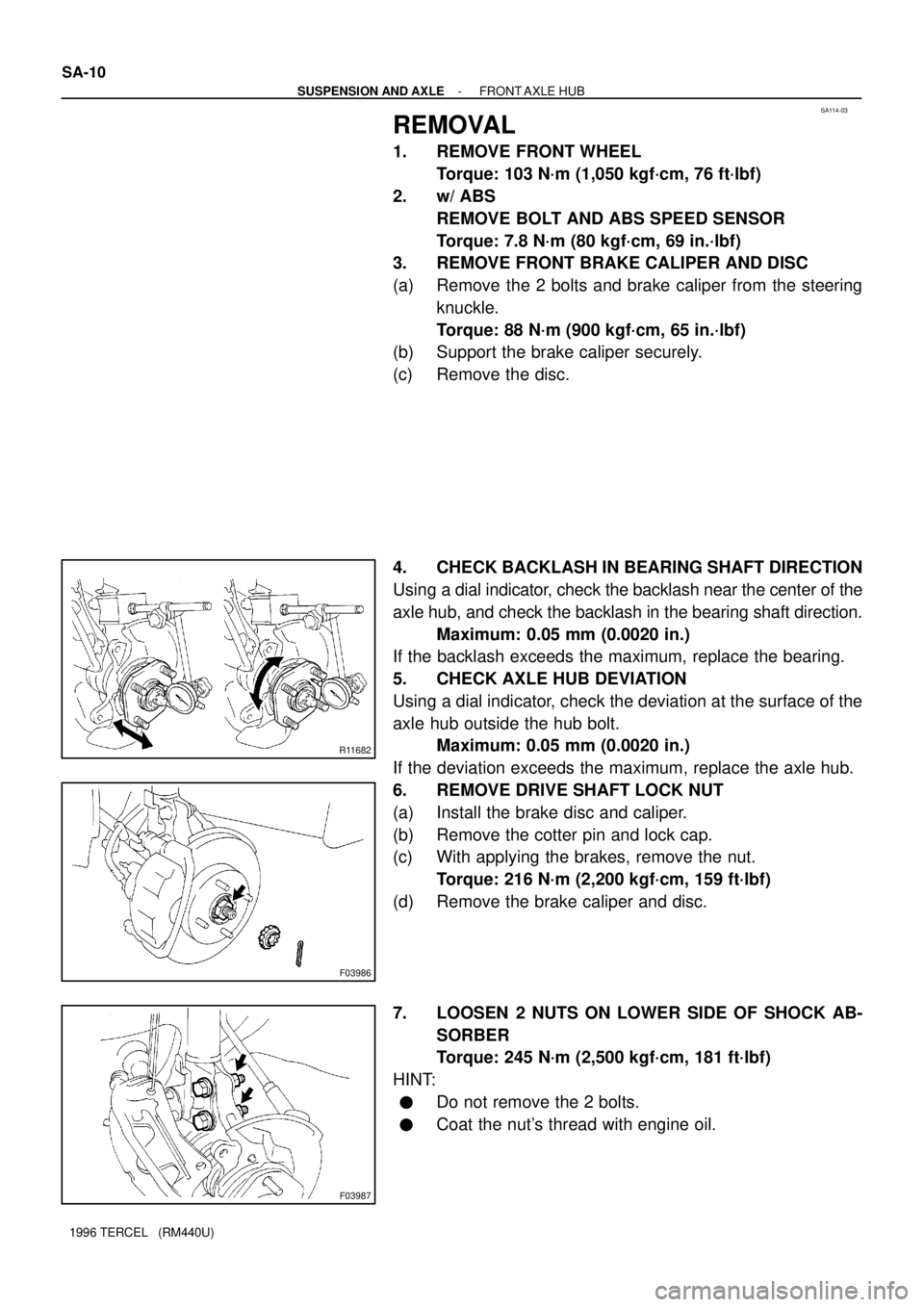
4. CHECK BACKLASH IN BEARING SHAFT DIRECTION
Using a dial indicator, check the backlash near the center of the
axle hub, and check the backlash in the bearing shaft direction.
Maximum: 0.05 mm (0.0020 in.)
If the backlash exceeds the maximum, replace the bearing.
5. CHECK AXLE HUB DEVIATION
Using a dial indicator, check the deviation at the surface of the
axle hub outside the hub bolt.
Maximum: 0.05 mm (0.0020 in.)
If the deviation exceeds the maximum, replace the axle hub.
6. REMOVE DRIVE SHAFT LOCK NUT
(a) Install the brake disc and caliper.
(b) Remove the cotter pin and lock cap.
(c) With applying the brakes, remove the nut.
Torque: 216 N´m (2,200 kgf´cm, 159 ft´lbf)
(d) Remove the brake caliper and disc.
7. LOOSEN 2 NUTS ON LOWER SIDE OF SHOCK AB-
SORBER
Torque: 245 N´m (2,500 kgf´cm, 181 ft´lbf)
HINT:
�Do not remove the 2 bolts.
�Coat the nut's thread with engine oil.
Page 833 of 1202
SA118-03
N00187
SST
N00188
Washer SA-16
- SUSPENSION AND AXLEFRONT WHEEL HUB BOLT
832 Author�: Date�:
1996 TERCEL (RM440U)
FRONT WHEEL HUB BOLT
REPLACEMENT
1. REMOVE FRONT WHEEL
2. REMOVE BRAKE CALIPER AND DISC
(See page SA-10)
3. REMOVE HUB BOLT
Using SST, remove the hub bolt.
SST 09628-1001 1
4. INSTALL HUB BOLT
Install washer and nut to the hub bolt, as shown in the illustra-
tion, and install the hub bolt with torquing the nut.
5. INSTALL DISC AND BRAKE CALIPER
(See page SA-10)
Torque: 88 N´m (900 kgf´cm, 65 ft´lbf)
6. INSTALL FRONT WHEEL
Torque: 103 N´m (1,050 kgf´cm, 76 ft´lbf)
Page 835 of 1202

SA128-02
FA1535
SST
F03986
SA-18
- SUSPENSION AND AXLEFRONT DRIVE SHAFT
1996 TERCEL (RM440U)
REMOVAL
NOTICE:
�The hub bearing could be damaged if it is subjected
to the vehicle weight, such as when moving the ve-
hicle with the drive shaft removed. Therefore, if it is
absolutely necessary to place the vehicle weight on
the hub bearing, first support it with SST.
SST 09608-16042 (09608-02021, 09608-02041)
�w/ ABS:
After disconnecting the drive shaft from the axle hub,
work carefully so as not to damage the sensor rotor
serrations on the drive shaft.
1. REMOVE FRONT WHEEL
Torque: 103 N´m (1,050 kgf´cm, 76 ft´lbf)
2. M/T:
REMOVE LH ENGINE UNDER COVER
3. DRAIN TRANSAXLE OIL (M/T) OR ATF (A/T)
4. w/ ABS:
REMOVE BOLT AND ABS SPEED SENSOR
Torque: 7.8 N´m (80 kgf´cm, 69 in.´lbf)
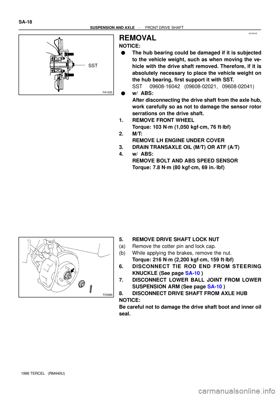
5. REMOVE DRIVE SHAFT LOCK NUT
(a) Remove the cotter pin and lock cap.
(b) While applying the brakes, remove the nut.
Torque: 216 N´m (2,200 kgf´cm, 159 ft´lbf)
6. DISCONNECT TIE ROD END FROM STEERING
KNUCKLE (See page SA-10)
7. DISCONNECT LOWER BALL JOINT FROM LOWER
SUSPENSION ARM (See page SA-10)
8. DISCONNECT DRIVE SHAFT FROM AXLE HUB
NOTICE:
Be careful not to damage the drive shaft boot and inner oil
seal.
Page 840 of 1202
SA12B-02
- SUSPENSION AND AXLEFRONT DRIVE SHAFT
SA-23
1996 TERCEL (RM440U)
INSTALLATION
Installation is in the reverse order of removal (See page SA-18).
HINT:
After installation, check ABS speed sensor signal and front wheel alignment (See page DI-1 11 and
SA-4).
Page 842 of 1202
SA1W8-02
- SUSPENSION AND AXLEFRONT SHOCK ABSORBER
SA-25
1996 TERCEL (RM440U)
REMOVAL
1. REMOVE FRONT WHEEL
Torque: 103 N´m (1,050 kgf´cm, 76 ft´lbf)
2. REMOVE FLEXIBLE HOSE
Remove the bolt and disconnect the flexible hose from the shock absorber.
Torque: 29 N´m (300 kgf´cm, 22 ft´lbf)
3. w/ ABS:
DISCONNECT ABS SPEED SENSOR WIRE HARNESS
Remove the bolt and disconnect the ABS speed sensor wire harness from the shock absorber.
Torque: 5.4 N´m (55 kgf´cm, 48 in.´lbf)
4. DISCONNECT SHOCK ABSORBER FROM STEERING KNUCKLE
Remove the 2 nuts and bolts and disconnect the shock absorber from steering knuckle,
Torque: 245 N´m (2,500 kgf´cm, 181 ft´lbf)
HINT:
Coat the nut's threads with engine oil.
5. REMOVE SHOCK ABSORBER AND COIL SPRING
(a) Remove the 3/4 nuts on the upper side of the shock absorber.
Torque: 39 N´m (400 kgf´cm, 29 ft´lbf)
(b) Remove the shock absorber with the coil spring.
Page 847 of 1202
SA11F-02
SA-30
- SUSPENSION AND AXLEFRONT SHOCK ABSORBER
1996 TERCEL (RM440U)
INSTALLATION
Installation is in the reverse order of removal (See page SA-25).
HINT:
After installation, check front wheel alignment (See page SA-2).